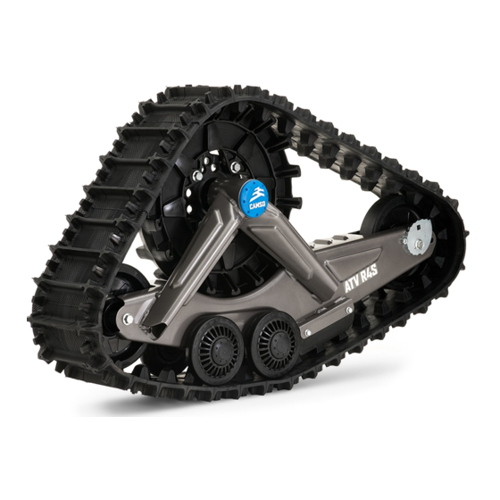
CAMSO ATV R4S Adjustments
Hide thumbs
Also See for ATV R4S:
- User manual (50 pages) ,
- Installation manuallines (20 pages) ,
- Owner's manual (36 pages)
Advertisement
Quick Links
Advertisement

Summary of Contents for CAMSO ATV R4S
- Page 1 CAMSO ATV R4S FOR ALL-TERRAIN VEHICLES ATV R4S: 1099-01-1340...
- Page 2 Incorrect adjustments can decrease the performance of the systems and result in premature wear or breakage of certain components. 1099-00-7731 - VERSION A are trademarks of Camso inc. ® All rights reserved. ©2019 Camso inc. Printed in Canada.
- Page 3 The serial number’s last digit (0, 1, 2, 3) indicates the mounting position on the vehicle. Lay out the track systems accordingly. Refer to Figure 1 and Figure 2. NOTE: If Track System serial numbers do not match, contact your authorized Camso dealer / distributor. Figure 1...
- Page 4 ADJUSTMENTS NOTE: To make the following adjustments, position the NOTE: Before each measurement, temporarily apply vehicle on a flat and level surface. light pressure to the front of the track to make sure that it stays flat on the ground. ANGLE OF ATTACK - FRONT SYSTEMS •...
- Page 5 ADJUSTMENTS • Position a flat bar on top of the rear wheels of the front Track System and measure from the ground up to the flat bar as shown on Figure 7. Figure 8 • Loosen nut (3) compressing stabilizing rod spring.
- Page 6 ADJUSTMENTS • Loosen jam nut (1). Turn stabilizing arm (3) to adjust length of rod end (2) so that rubber cone (4) applies light pressure on anti–rotation retainer (5). Figure 14. Figure 11 • IMPORTANT: Double-check minimum distance between nut and stabilizing arm guide.
- Page 7 ADJUSTMENTS ALIGNMENT Adjustment Method To adjust the ATV’s steering system, first loosen Parallelism must be adjusted with the ATV on the coupling rod nuts (1), then screw or unscrew the ground, driving the vehicle forward about 3 coupling rod (2) an equal number of revolutions meters [10 ft.] and measuring toe–in distance.
- Page 8 ADJUSTMENTS Measure A: Measure the distance inside the front Measure B: Measure the distance inside the rear ends of the front Track System frames. See ends of the front Track System frames. See Figures 18, 19 and 20. Figures 21, 22 and 23. Figure 18 Figure 21 Figure 22 (Distance inside front frames - rear end)
-
Page 9: Track Tension
ADJUSTMENTS TRACK TENSION • After having adjusted the tension and verified cam positions, re-tighten both wheel shaft bolts to 50 N-m (37 lb-ft) of torque. • Loosen both tensioner side wheel shaft bolts (1), enough to allow tensioner cams (2) to turn. Figure 24. -
Page 10: Basic Tuning
• Lower rubber track tension provides better traction, a smoother ride and better fuel economy. NOTE: The track tension testing tool shown below in Figure 30 can be purchased through an authorized Camso dealer. Part #2000-00- 3125. Figure 30 Figure 31 Final Check Ride at slow speed on a distance of about 1.5 km... -
Page 11: Component Installation
CAMSO ATV R4S TRACK SYSTEMS INSTALLATION AND ADJUSTMENT CHECKLIST ** Steps in this checklist are laid out in logical order. They should be performed in succession to optimize the track system installation on the vehicle. ** 1 - COMPONENT INSTALLATION A - INSTALLATION OF REAR ANCHOR BRACKETS * Refer to INSTALLATION GUIDELINES section entitled "Rear track systems"...


Need help?
Do you have a question about the ATV R4S and is the answer not in the manual?
Questions and answers