Table of Contents
Advertisement
Quick Links
Service Manual
Applicable models
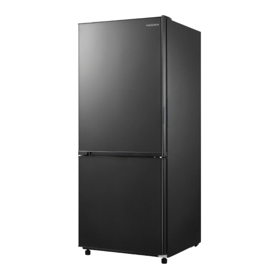
UL-BCD283WE-DQ
UR-BCD283WE-SQ
CE-BCD283WE-MT
(The picture is only for reference, and specific appearance and configuration are subject to the real
product)
Prepared by
Reviewed by
Approved by
Service Manual, 2016-12
Model No.
22031020000054
22031020000057
22031020000060
R&D:Zheng Qiang
QA:Wang Tao
SVC:Zhang Kun
R&D:Geng Xiuhua
SVC:Guang Taoshuai
1 / 46
Advertisement
Table of Contents

Related Manuals for Midea UL-BCD283WE-DQ


Summary of Contents for Midea UL-BCD283WE-DQ
- Page 1 Service Manual, 2016-12 Service Manual Applicable models Model No. UL-BCD283WE-DQ 22031020000054 UR-BCD283WE-SQ 22031020000057 CE-BCD283WE-MT 22031020000060 (The picture is only for reference, and specific appearance and configuration are subject to the real product) Prepared by R&D:Zheng Qiang QA:Wang Tao Reviewed by SVC:Zhang Kun R&D:Geng Xiuhua...
- Page 2 Midea Refrigerators Technical Maintenance Manual Copyright @2016 All rights reserved. Replication of all or part of the Manual in any forms shall not be allowed without written approval by the Overseas Sales Corporation of Midea Refrigerators. 2 / 46...
-
Page 3: Table Of Contents
Service Manual, 2016-12 Contents 1.SAFETY WARNING CODE ......................5 ....................5 1.1W ARNING FOR OPERATION SAFETY ..................8 1.2S AFETY INSTRUCTION FOR REFRIGERANT 2.DESCRIPTION FOR PRODUCT FEATURES ................9 3.INSTALLATION AND COMMISSIONING ................10 ............................. 10 3.1H ANDLING ) ........................10 3.2D ISASSEMBLY ...................... - Page 4 Service Manual, 2016-12 ....................27 8.7D ISPLAY AND MAIN CONTROL PANEL ) ........................29 8.8 B AR COUNTER ) ......................29 8.9 W ATER DISPENSER ) ........................29 8.10 I CE MAKER ................29 9. F 9.1O UNCTION AND OPERATION PERATION PANEL ........................
-
Page 5: Safety Warning Code
Service Manual, 2016-12 1.Safety Warning Code 1.1Warning for operation safety 5 / 46... - Page 6 Service Manual, 2016-12 6 / 46...
- Page 7 Service Manual, 2016-12 7 / 46...
-
Page 8: Safety Instruction For Refrigerant
Service Manual, 2016-12 1.2Safety instruction for refrigerant 8 / 46... -
Page 9: Description For Product Features
Service Manual, 2016-12 2.Description for product features This product is provided with following features: (The picture is only for reference, and specific appearance and configuration are subject to the real product) 1)Full air-cooling and frost-free design2)door is reversible, for meeting the requirements of consumers who have different usage habit;... -
Page 10: Installation And Commissioning
Service Manual, 2016-12 3.Installation and commissioning 3.1Handling 1) Protecttherefrigeratorinmovingit Sameasshownasleftphoto,pleasemoveitbyhandcartwi thcushion 2) Removeallpackingmaterialsandbottomcushion,then moveintohouseforplacement 3) Aftermovingittoappropriatelocation,waitfor2hoursbe forepoweron. 3.2Disassembly (None) The refrigerator door needs to be dismantled if it cannot enter the room in the whole. 3.3 Installation location Location that is easy for ventilation shall be chosen to facilitate heat dissipation, enhance its performance and reduce the energy consumption. -
Page 11: Leveling Of The Refrigerator
Service Manual, 2016-12 3.4 Leveling of the refrigerator If the refrigerator cannot be placed steadily, adjust the footing to level it. 3.5Change the door opening direction Unplug your refrigerator and remove all food from the door shelves. Remove the left cover plate and the right top hinge cover, then unscrew and remove the right top hinge. - Page 12 Service Manual, 2016-12 Unscrew the two screws holding the bottom hinge, then remove the bottom hinge from the bottom right side of the refrigerator. take out the left bottom hinge assembly from the accessory bag, place the hinge assembly on proper position and fix it by two screws Remove the door block from the bottom, right side of the door and attach it...
-
Page 13: Installation Of Handle(None
Service Manual, 2016-12 10. Put the door onto the refrigerator center left hinge, then attach the top left hinge to the top of refrigerator. Cover the hinge with the top left hinge cover and cover the screw holes on the right side of the top with the cover plate you previously removed. -
Page 14: Terms
Service Manual, 2016-12 4.Terms 4.1 Definition of model(None) 4.2Location of nameplate Label (The picture is only for reference, and specific appearance and configuration are subject to the real product) 14 / 46... -
Page 15: Product Specification
Service Manual, 2016-12 5.Product specification 5.1 typespecification(None) 5.2 Electrical parameters Product Name UL-BCD283WE-DQ UR-BCD283WE-SQ CE-BCD283WE-MT 22031020000054 22031020000057 22031020000060 Product Code Name Item Type Specification Specification Specification EE50H1Z EZ80E1C PZ90H1C Compressor EA19C3/QP2-15 8EA14C3 QPE2-A4R7MD3 Starter TM149SFBYY/ Overload 4TM283RFBYY DRB25S61A1 DRB16S61A1BT40-135A61D3 protector Winding Rmc:10-20Ω... -
Page 16: Inside Temperature
Service Manual, 2016-12 5.3Inside temperature Temperature tolerance ≤ 2 The highest ( Lowest ( Compartment Freezing Refrigerating Variable temperature 5.4Defrosting parts Initial defrosting period Normal defrosting period Defrosting period Temperature is lower than 0 6~24 hours Defrosting sensor B3839 Can’t be restored Thermal fuse 115V/200W Steel pipe... -
Page 17: Internal View And Dimension
Service Manual, 2016-12 6.Internal view and dimension 6.1Main parts and their names (The picture is only for reference, and specific appearance and configuration are subject to the real product) Refrigerator chamber Freezer chamber 1.TEMP control panel 7.steel wire drawer 2.Glass shelve 8.Regulating foot 3.control knob 9.container... - Page 18 Service Manual, 2016-12 Down view Open Door Maximum open angle of door(135°) 18 / 46...
- Page 19 Service Manual, 2016-12 (The picture is only for reference, and specific appearance and configuration are subject to the real product) 19 / 46...
-
Page 20: Refrigerating Piping System And Circulating Route Of Cooling Air
Service Manual, 2016-12 7.Refrigerating piping system and circulating route of cooling air 7.1 Refrigerating piping system 1Compressor 2Exhaust transition pipe3Left condenser4Anti-condensationg tube5Right condenser6Dry filter7Capillary tube 8Evaporator9Return pipe10Return transition pipe (The picture is only for reference, and specific appearance and configuration are subject to the real product) 20 / 46... -
Page 21: Circulating Route Of Cooling Air
Service Manual, 2016-12 7.2Circulating route of cooling air (The picture is only for reference, and specific appearance and configuration are subject to the real product) 21 / 46... -
Page 22: Dismantling Of Parts
Service Manual, 2016-12 8. Dismantling of parts 8.1 Parts on the door Door seal Door seal is installed into door liner groove. 1) Open the refrigerator door; 2) Take the door seal ①out of door liner; Door tray Lift up the bottle frame and take it out from the door liner of the refrigerator. -
Page 23: Light System
Service Manual, 2016-12 1) Pull out the partition plate completely. 2) Lift it up and take it out from the refrigerator. Ice tray None Refrigerator tray None Drawer None 8.3Light system Light Light of the refrigerating chamber is located upper chamber 1)... -
Page 24: Evaporator And Temperature Sensing System
Service Manual, 2016-12 1) usescrewdrivertoremovethe2screwson the back of Freezer air duct,then remove rhe front cover,fan motor assembly can be taken out 2) seperatethefanbladefromfanmotor(pullforcibly) 3) use screwdrivertoremovethescrew, thenseperatethebracketfromfanmotor 4) angethefanmotor,thereverseoperationforassembly Damper assembly (None) Evaporator and temperature sensing system Evaporator in freezing chamber 24 / 46... - Page 25 Service Manual, 2016-12 1) Remove the air duct components in freezing chamber. 2) Disconnect all connectors. 3) Remove the welding on inlet and outlet tubes. 4) Remove two screws which are used to fix the evaporator and remove the evaporator. Components on the evaporator Fuse The fuse is located on top of the evaporator...
-
Page 26: Compressor Case
Service Manual, 2016-12 Before remove the sensor, the freezer duct assembly should be removed 1) Remove the air duct assembly from the freezer. 2) Remove the sensor. Ambient temperature sensor None Freezer sensor None 8.6Compressor case Rear cover and compressor case None Condenser fan moto None... -
Page 27: Display And Main Control Panel
Service Manual, 2016-12 2. Remove the clipping strip Slowly pull it out 3. Remove the protective cover 1Pry the protective cover slowly from the upper part, 2Pull it out and remove it. 4. Remove the starter and protector Unplug the starter and protector (you can use a screwdriver to pry it slowly) 5. - Page 28 Service Manual, 2016-12 * The temperature control indication sticker is likely to be damaged when replacing PCB, thus it is advised to prepare one for standby before replacement: Main control board 1) use cross screwdriver to remove the two screws of main PCB cover 2) use slotted screwdriver to dismantle the PCB cover, unplug the wiring connectors...
-
Page 29: Bar Counter(None)
Service Manual, 2016-12 Bar counter(None) Disassembly and installation of bar counter None Disassembly and installation bar doorseal None Water dispenser(None) Disassembly and installation of water valve None Disassembly and installation of water tank None Ice maker(None) 8.10 Disassembly and installation of ice maker None Disassembly and installation of water system None... -
Page 30: Setting Of The Gear
Service Manual, 2016-12 At the first time of power-on, the display screen (including button light) will be bright for 3 seconds and then press the middle gear to show operation Display Normal operation displayWhen failure occurs, the corresponding LED light group will display fault code (circular display);If no failure occurs, the current operation gear will be displayed. -
Page 31: Defrosting Function
Service Manual, 2016-12 Failure The LED2 and Step1: dismantle the display control panel and display button switch LED3 lighten PCB, to check whether the button on display PCB is stuck by other objects long same time Step 2: change the display PCB. time and blink 9.6Defrosting function... -
Page 32: Self-Diagnosis
Service Manual, 2016-12 8° C and the defrosting heater has been working for 1 hour, Select to Enter into test mode and press then the refrigerator will exit the test mode and exit button for the third time return to normal operation mode test mode 9.8Self-diagnosis ... -
Page 33: Door Trip Test Circuit(None)
Service Manual, 2016-12 Door trip test circuit(None) 10.2 Temperature test circuit 10.3 It’s conducted by the sensor, making use of the characteristics that resistance value reduces as the temperature increases, and the thermistor that has temperature coefficient of resistance in medium temperature. -
Page 34: Fan Motor Circuit Of The Freezing Chamber
Service Manual, 2016-12 Fan motor circuit of the freezing chamber 10.4 The fan in the freezing chamber is running when the compressor is operating. Check 12V and FAN to see if there is a voltage of 12V. When in normal operation, the fan is in low level and the voltage between 12V and FAN is more than 11V. - Page 35 Service Manual, 2016-12 18.9 8.392 3.972 2.005 1.071 17.87 7.968 3.788 1.919 1.029 16.9 7.568 3.613 1.838 0.9885 15.98 7.19 3.447 1.761 0.9506 15.12 6.833 3.29 1.687 0.914 35 / 46...
-
Page 36: Troubleshooting Method
Service Manual, 2016-12 11.Troubleshooting Method 11.1 No refrigeration 36 / 46... - Page 37 Service Manual, 2016-12 37 / 46...
-
Page 38: Compressor Failure
Service Manual, 2016-12 11.2 Compressor failure 38 / 46... -
Page 39: Defrosting Is Not Working
Service Manual, 2016-12 11.3 Defrosting is not working 39 / 46... -
Page 40: Fan In The Freezing Chamber Is Abnormal
Service Manual, 2016-12 11.4 Fan in the freezing chamber is abnormal Refer to this method for other fans. 40 / 46... -
Page 41: Damper Is Abnormal(None)11.6 Lights Inside The Refrigerator Don't Light Up
Service Manual, 2016-12 11.5 Damper is abnormal(None)11.6 Lights inside the refrigerator don’t light up 41 / 46... -
Page 42: Figures And Details Of Repair Parts(Documents Are Provided Separately)
Service Manual, 2016-12 12. Figures and details of repair parts( Documents are provided separately 12.1 Figure 12.2 List of parts and components 13Appendix: 13.1Electrical Schematic Diagram 13.2refrigerator maintenance tooling and equipment and material Tooling Name Photo Main Usage Phillips screwdriver screw assemble and disassemble 42 / 46... - Page 43 Service Manual, 2016-12 screw and rivet assemble and slotted screwdriver/scraper disassemble hinge and compressor screw Socket spanner 5/16″ assemble and disassemble display panel and air duct Sucker cover disassemble handle assemble and Allen wrench(2.8~4mm) disassemble Vise grip pliers sealing process tube Pipe cutter pipe cutting Knife...
- Page 44 Service Manual, 2016-12 Nipper pliers assistive tool Capillary tube scissors Shear capillary Equipment Name Photo Main Usage Vacuum pump vacuum pumping Electronic scale weighing refrigerant/gas pipe and cooling High pressure nitrogen with system(condenser, evaporator, piezometer etc) impurities clean Soldering gun heating and welding 44 / 46...
- Page 45 Service Manual, 2016-12 connection process Quick coupling pipelinevacuumorchargerefriger antwillbeused. welding point leakage detect, if hand leak detector no, use soap-suds material Name Photo Main Usage Process pipeline Chargetherefrigerant Involving a system failure to be Dry filter replaced Copper welding rod tube welding Refrigerant/gas Add refrigerant to the system...
- Page 46 Service Manual, 2016-12 Midea Refrigerators If you need to get detailed technical information from the manufacturer, please contact: xxx@midea.com Refrigeration Division Overseas Sales Company Address: No. 176, Jinxiu Avenue, Economic-Technological Development Area, Hefei, Anhui, China 46 / 46...
Need help?
Do you have a question about the UL-BCD283WE-DQ and is the answer not in the manual?
Questions and answers