Table of Contents
Advertisement
Quick Links
Service Manual_2020-V1.0
Service Manual
TMF No Frost Series
Applicable Models
Product Models
Applicable Models
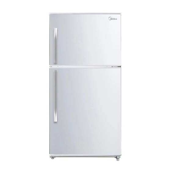
HD-663FWEN
UR-BCD510WE-SQ
22031020006981
The picture in this service manual is only for reference, and specific appearance
and configuration are subject to the real product.
This manual mainly teaches the method, the specific work skill needs engineer
to accumulate through the daily work.
1
Advertisement
Table of Contents

Related Manuals for Midea TMF No Frost Series


Summary of Contents for Midea TMF No Frost Series
- Page 1 Service Manual_2020-V1.0 Service Manual TMF No Frost Series Applicable Models Product Models Applicable Models HD-663FWEN UR-BCD510WE-SQ 22031020006981 The picture in this service manual is only for reference, and specific appearance and configuration are subject to the real product. This manual mainly teaches the method, the specific work skill needs engineer...
- Page 2 Manufacturers or distributors are not responsible for the content of the Manual and interpretation thereof. Midea Refrigerators Technical Maintenance Manual Copyright @2017 All rights reserved. Replication of all or part of the Manual in any forms shall not be allowed without written approval by the Overseas Sales Corporation of Midea Refrigerators.
-
Page 3: Table Of Contents
Service Manual_2020-V1.0 Contents SIGNIFICANT UPDATE NOTES (NONE) ......................5 2. SAFETY WARNING ............................... 6 2.1 W ........................... 6 ARNING FOR OPERATION SAFETY ......................... 8 2.2 S AFETY INSTRUCTION FOR REFRIGERANT 3. INSTALLATION AND COMMISSIONING ......................9 ................................... 9 3.1 H ANDLING 3.2 D ........................ - Page 4 Service Manual_2020-V1.0 8. TEMPERATURE SENSING SYSTEM ......................... 35 ............................35 8.1 P OSITION OF SENSORS ........................... 35 8.2 R EPLACEMENT OF SENSORS 8.3 S ......................36 ENSOR WITHOUT TERMINAL REPLACEMENT 8.4 S ..............................37 ENSOR TABLE 9. FUNCTION AND OPERATION ..........................39 .............................
-
Page 5: Significant Update Notes (None)
Service Manual_2020-V1.0 1. Significant update notes (None) -
Page 6: Safety Warning
Service Manual_2020-V1.0 2. Safety Warning 2.1 Warning for operation safety Important Safety Instructions CAUTION RISK OF ELECTRIC SHOCK DO NOT OPEN This symbol indicates that dangerous voltage constituting a risk of electric shock is present within your freezer. This symbol indicates that there are important operating and maintenance instructions in the literature accompanying your freezer. - Page 7 Service Manual_2020-V1.0 CONNECTING ELECTRICITY Electrical Shock Hazard. Failure to follow these instructions can Plug into a grounded 3-prong outlet. result in death, fire, or electrical shock. Do not remove the ground prong. Do not use an adapter. WARNING Electric Shock Hazard Failure to follow these instructions can result in electric shock, fire, or death.
-
Page 8: Safety Instruction For Refrigerant
Service Manual_2020-V1.0 13) Do not store or use gasoline or any flammable liquids inside or in the vicinity of this freezer. 14) Do not use extension cords or ungrounded (two-prong) adapters with this freezer. If the power cord is too short, have a qualified electrician install an outlet near the freezer. Use of an extension cord can negatively affect the freezer’s performance. -
Page 9: Installation And Commissioning
Service Manual_2020-V1.0 3. Installation and commissioning 3.1 Handling Handling Protect the refrigerator in moving it,Same as shown as left photo, please move it by handcart with cushion Remove all packing materials and bottom cushion, the move into house for placement After moving it to appropriate location, wait for 2 hou rs before power on. -
Page 10: Leveling Of The Refrigerator
Service Manual_2020-V1.0 3.4 Leveling of the refrigerator Leveling of the refrigerator If the refrigerator cannot be placed steadily, adjust the footing to level it. Turn the feet clockwise to raise the refrigerator; turn the feet counterclockwise to lower the refrigerator. 3.5 Left or right open door reversal Door reversal Power off and remove all food from the fridge. - Page 11 Service Manual_2020-V1.0 5)Remove the bottom hinge and screws. 6) Unscrew the hinge shaft from the right side of the bottom hinge and move it to the left side, then secure the bottom hinge to the bottom left side of the refrigerator. 7) Dismantle the sleeves, hole cap, screws and door stopper on the refrigerator door, and assemble them on the other side.
-
Page 12: Installation Of Handle(Option
Service Manual_2020-V1.0 10)Put down the refrigerator door on the bottom hinge, take out the middle hinge of the other side from the accessory plastic bag, then assemble the middle hinge. 11)Put down the freezer door on the middle hinge, then take out the top hinge and cover of other side from the accessory plastic bag. - Page 13 Service Manual_2020-V1.0 3)Fix the bolts① in the screw hole on the front of the door. 4) Install the door handle② onto the bolts. 5)Tighten the Allen screws③ in the door handle hole. 6)Install the screw cover④ on the screw of the door handle.
-
Page 14: Main Parts And External Dimension
Service Manual_2020-V1.0 4. Main parts and external dimension 4.1 Main parts (The picture is only for reference, and specific appearance and configuration are subject to the real product) -
Page 15: External Dimension
1270 (The picture is only for reference 4.3 Midea product serial number and location 1) Product Serial Number — Including order number, production date and other information. When the product occur problem, it needs to be recorded or photographed and provided to us. - Page 16 Service Manual_2020-V1.0 2)Paste location Some products also have S/N on the lower part of the right side of the Cabinet.
-
Page 17: Electric Control System
Service Manual_2020-V1.0 5. Electric control system 5.1 Electrical parts parameters Applicable Model HD-663FWEN Product Model UR-BCD510WE-SQ 22031020006981 Product code Rated Voltage 115V、60Hz Item Specification Specification Refrigerant R600a EZ65H1A (GMCC) Compressor (Part code : 11101010012233) Starting device type Fixed Speed The COP of compressor 1.72(W/W) The max cooling capacity of 133 W... - Page 18 Service Manual_2020-V1.0 ■ Mechanical switch Switch of the light None □ Magnetism control switch Defrosting parts Defrosting sensor NTC B3839 ( B5/25=3839K± 2% ) 230V、73(0 ~ -5) ℃ Fuse in freezing chamber Defrost heater in freezing chamber 115V、180W...
-
Page 19: Circuit Diagram
Service Manual_2020-V1.0 5.2 Circuit diagram F: Freezer R: Refrigerator... -
Page 20: Main Pcb Terminal Connection Diagram
Service Manual_2020-V1.0 5.3 Main PCB terminal connection diagram Connecting terminals Connecting terminals 1、 Compressor 5、 Ambient temperature sensor 2、 Freezing frost heater 6、 Freezing defrost sensor 3、 Ice maker 7、 Refrigeration sensor 4、 Freezing fan motor... -
Page 21: Refrigeration System
Service Manual_2020-V1.0 6. Refrigeration system 6.1 Refrigeration system working principle ❶Compressor→❷ Anti-condensation tube→❸ Condenser→❹ Dry filter→❺ Capillary tube→❻ Evaporator→❼ Suction tube→❶Compressor 6.2 Cooling pipeline and drain pipe inside the cabinet... -
Page 22: Circulating Route Of Cooling Air
Service Manual_2020-V1.0 6.3 Circulating route of cooling air 6.4 Welding points in chambers or foam layer 1) Welding points on freezer evaporator Welding point Pipe outer diameter (mm) 1-Freezer capillary and inlet of evaporator Aluminum pipe: Copper pipe: Φ6 Φ6.0 2-Heat transition tube and outlet of evaporator Aluminum pipe: Copper pipe: Φ6... -
Page 23: Welding Point In The Compressor Case
Service Manual_2020-V1.0 6.5 Welding point in the compressor case Welding point Pipe outer diameter (mm) 1-Inlet of anti-condensation tube and outlet of venting Steel pipe: Φ4.0 Steel pipe: Φ4.0 connection tube 2-Inlet of condenser tube and outlet of anti-condensation tube Steel pipe: Φ4.0 Steel pipe: Φ4.0 Steel pipe: Φ4. -
Page 24: Dismantling Of Parts
Service Manual_2020-V1.0 7. Dismantling of parts 7.1 Parts on the door Door seal Door seal is installed into door liner groove. 1)Open the refrigerator door; 2)Take the door seal out of door liner; Door tray While squeezing it inward, lift up the door tray and take it out from door liner. -
Page 25: Light System
Service Manual_2020-V1.0 Shelves Lift up the division plate with a proper force and pull it out towards yourself; Freezer Drawer(None) None None 7.3 Light system Light Light of the refrigerating 1)Remove the lamp cover 2)Remove the light. 3) The reverse process can complete installation. Light of the freezing None Light switch... -
Page 26: Air Duct Components In Freezing Chamber And Fan Motor
Service Manual_2020-V1.0 1)Remove two screws from the refrigerating air duct with a cross screwdriver; 2)Pull all connector terminals out of the refrigerating air duct to remove its components; Fan motor of air duct None 7.5 Air duct components in freezing chamber and fan motor Air duct components in freezing chamber All accessories in the freezing chamber should be dismantled before removing the air duct components. -
Page 27: Evaporator And Defrost System
Service Manual_2020-V1.0 4)Take out the freezing air duct assembly. Fan motor of air duct 1)Disassemble buckles at the back of the freezing air duct and remove 4 front cover plates; 2) Remove screws using a cross screwdriver to get the fan and components of fan brackets;... -
Page 28: Compressor Case
Service Manual_2020-V1.0 1)Remove the air duct components in freezing and variable temperature chamber. 2)Disconnect all connecting terminals. 3)Remove the welding on inlet and outlet tubes. 4)Remove the evaporator. Components on the evaporator Defrost heater with defrost sensor and fuse, it can be replaced separately. - Page 29 Service Manual_2020-V1.0 1-Power cord 4-Drain tray 1 2-Dry filter 5-Suction connection tube6-Drain tray 2 3-Compressor Disassembly and assembly of compressor 1) Cut off the power, remove the goods in the refrigerator, with the tape to make the door fixed firmly and prevent the door dropping when the refrigerator dumping.
- Page 30 Service Manual_2020-V1.0 4-2)Remove the metal clamp(for some models) -Disassembly the metal clamp that is fix the electric appliance shield 5)Remove the clipping strip Slowly pull it out 6)Remove the protective cover -Pry the protective cover slowly from the upper part, -Pull it out and remove it.
- Page 31 Service Manual_2020-V1.0 8)Loosen the screw of the compressor bottom plate, remove the floor together with the compressor from the box. 9)Use the wrench to remove the bolts by steps❹❺❻❼, replace the compressor and reverse process can complete installation. 10)Use Pipe cutter cut off the condenser tube❽, then Shear off capillary ❾...
- Page 32 Service Manual_2020-V1.0 12)Replace the filter, Cu-Fe tubes welding ⓭ used Ag welding rod, Cu-Cu tubes welding ⓮ used Cu welding rod. 13)Vacuum system,The degree of vacuum below 6Pa. 14)Perfusion refrigerant. 15)Use the vise grip pliers clamp the middle of the process pipe, then seal welding process tube⓯⓰.
-
Page 33: Display Control Board
Service Manual_2020-V1.0 7.8 Display control board Display control board 1)When the display control board is installed on the refrigeration air duct, first remove the refrigeration air duct assembly. 2) Tear off the display control panel surface as shown in the picture. 3)Use a screwdriver to remove the display control panel mounting box. -
Page 34: Main Control Board
Service Manual_2020-V1.0 7.9 Main control board Main control board 1)When the main control board is installed on the refrigeration air duct, first remove the refrigeration air duct assembly. 2) Tear off the main control panel surface as shown in the picture. 3)Use a screwdriver to remove the main control panel mounting box. -
Page 35: Temperature Sensing System
Service Manual_2020-V1.0 8. Temperature sensing system 8.1 Position of sensors Position of sensors Have3 sensors ②Sensor in refrigerating chamber ④Ambient temperature sensor ⑦Defrost sensor in freezing chamber 8.2 Replacement of sensors Sensor in refrigerating chamber The refrigerating air duct components should be dismantled before removing this sensor. -
Page 36: Sensor Without Terminal Replacement
8.3 Sensor without terminal replacement Sensor replacement guidelines Cut off the damaged head of sensor. Strip off the sensor wiring. Take out a new sensor to cut the head of sensor. (Spare parts code:11201007000795) Its technical specifications apply to all MIDEA refrigerators. -
Page 37: Sensor R/Ttable
Service Manual_2020-V1.0 Strip off the head of the sensor and connect it. Wrap the two wires together with insulation tape. Wrap the two wires together. 8.4 Sensor R/T table Tx(℃) Tx(℉) R(KΩ) Tx(℃) Tx(℉) R(KΩ) Tx(℃) Tx(℉) R(KΩ) -22.00 33.81 23.00 8.392 68.00... - Page 38 Service Manual_2020-V1.0 17.60 9.820 62.60 2.865 107.60 0.989 19.40 9.316 64.40 2.737 109.40 0.951 21.20 8.841 66.20 2.616 111.20 0.914...
-
Page 39: Function And Operation
Service Manual_2020-V1.0 9. Function and operation 9.1 Display operation panel Refrigeration chamber temperature control panel Button Icons A. Refrigerating chamber temperature gear setting ① Gear 1 ② Gear 2 ③ Gear 3 ④ Gear 4 ⑤ Gear 5⑥Standby mode (Fridge stop working) Freezing chamber temperature control knob 9.2 Temperature control 9.2.1Temperature setting of refrigerating chamber... -
Page 40: Mode Setting
Service Manual_2020-V1.0 9.2.2 Temperature setting of freezing chamber Temperature gear of COLD COLDER freezer chamber <-12℃ <-17.8℃ <-21℃ Temperature value 9.3 Mode setting 9.3.1 Standby mode 1)When the refrigerator is working, keep pressing the “SET” button for 3 seconds, the standby indicator will light up and the refrigerator will stop working. -
Page 41: Test Mode
Service Manual_2020-V1.0 9.7 Test mode All below functions are only for diagnosis and test purpose, we advise to restart the refrigerator by power on/off if have used these functions. Test items Setting Method Setting result The indicator lights of gears 1, 3 and 5 Keep pressing the “SET”... -
Page 42: Compressor
Service Manual_2020-V1.0 10. Compressor 10.1 Compressor on and off control specifications 1.1 When one of the following conditions is met, the compressor stops: 1) Measured temperature in refrigerator chamber ≤ Shutdown temperature of refrigerator chamber 2) Enter defrosting cycle 3) The compressor runs continuously for more than 3 hours, will stop at least 5 minutes 1.2 When compressor shutdown time has been more than 5 min, one of the following conditions is met, the compressor starts up: 1) Measured temperature in refrigerator chamber ≥... -
Page 43: Troubleshooting Method
Service Manual_2020-V1.0 11. Troubleshooting Method 11.1 No cooling (Air cooling-Electronic) - Page 44 Service Manual_2020-V1.0...
-
Page 45: No Working Of Compressor
Service Manual_2020-V1.0 11.2 No working of compressor... -
Page 46: Inside Frosting, No Defrosting
Service Manual_2020-V1.0 11.3 Inside frosting, no defrosting... -
Page 47: Inside Frosting, No Defrosting-Maintenance Guidelines
Service Manual_2020-V1.0 11.4 Inside frosting, no defrosting-Maintenance guidelines... -
Page 48: Light Is Not On
Service Manual_2020-V1.0 11.5 Light is not on... -
Page 49: Fan Failure
Service Manual_2020-V1.0 11.6 Fan failure 11.7 Defective defrost circuit... -
Page 50: Noise
Service Manual_2020-V1.0 11.8 Noise 11.9 Air duct not operated... -
Page 51: Ice Makernot Make Ice(Option
Service Manual_2020-V1.0 11.10 Ice makernot make ice(Option)... -
Page 52: Product Exploded View And Spare Parts List
Service Manual_2020-V1.0 12. Product exploded view and spare parts list Please log in to TSP system to view and download these contents. - Page 53 For more information about where you can drop off your waste for recycling, please contact your local authority, or where you purchased your product. Midea Refrigerators If you need to get detailed technical information from the manufacturer, please contact: xxx@midea.com...
Need help?
Do you have a question about the TMF No Frost Series and is the answer not in the manual?
Questions and answers