Vaisala HUMICAP HM70 User Manual
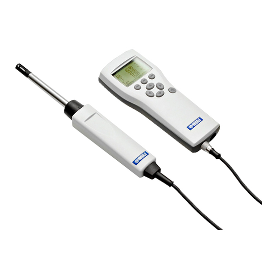
Handheld humidity and temperature meter
Hide thumbs
Also See for HUMICAP HM70:
- User manual (83 pages) ,
- Quick manual (40 pages) ,
- User manual (83 pages)

Related Manuals for Vaisala HUMICAP HM70


Summary of Contents for Vaisala HUMICAP HM70
- Page 1 M210297EN-G User Guide â Vaisala HUMICAP Handheld Humidity and Temperature Meter HM70...
- Page 2 English versions are This product contains software developed applicable, not the translations. by Vaisala or third parties. Use of the The contents of this document are subject software is governed by license terms and to change without prior notice.
-
Page 3: Table Of Contents
Table of contents Table of contents About this document..................7 Version information..................7 Related manuals....................7 Documentation conventions................8 Trademarks......................9 Product overview..................10 Introduction to HM70..................10 2.1.1 Basic features and options...............11 2.1.2 Overview of probes...................11 MI70 indicator....................13 MI70 indicator parts..................13 Installing and recharging MI70 batteries............ - Page 4 HM70 User Guide M210297EN-G Recording and viewing data................. 32 6.8.1 Recording data..................32 6.8.2 Viewing recorded data................32 6.8.3 Checking MI70 memory status.............. 32 6.8.4 Clearing data memory................33 6.8.5 Transferring recorded data to PC with MI70 Link....... 33 Other functions....................34 6.9.1 Setting an alarm..................
- Page 5 Table of contents Technical data....................60 10.1 HMP75, HMP76, and HMP77 specifications..........60 10.2 MI70 specifications..................63 10.3 Dimensions......................65 10.4 Spare parts and accessories................. 66 Maintenance and calibration services............69 Technical support.................... 69 Warranty......................69 Recycling......................69...
- Page 6 HM70 User Guide M210297EN-G List of figures Figure HMP75, HMP76, and HMP77 probes (left to right)........11 Figure 2 MI70 indicator parts..................13 Figure 3 Measurement error at 100 %RH with 1 °C difference between the ambient and sensor temperature........18 Figure 4 Display example with carbon dioxide and temperature and humidity probes connected simultaneously........19...
- Page 7 List of tables List of tables Table 1 Document versions (English)................7 Table 2 Related manuals....................7 Table 3 Display parameters.................... 10 Table 4 HMP75, HMP76, and HMP77 probe features..........12 Table 5 MI70 battery status indicator................14 Table 6 MI70 status icons....................23 Table 7 List of HM70 error messages................
- Page 8 HM70 User Guide M210297EN-G...
-
Page 9: About This Document
Chapter 1 – About this document 1. About this document 1.1 Version information This manual provides information for operating and maintaining Vaisala HUMICAPâ Handheld Humidity and Temperature Meter HM70. Table 1 Document versions (English) Document code Date Description M210297EN-G October 2020 This document. -
Page 10: Documentation Conventions
HM70 User Guide M210297EN-G Document code Name M211726EN Vaisala Humidity and Temperature Transmitter HMDW110 Series User Guide M211399EN Vaisala Humidity and Temperature Transmitter HMW90 Series User Guide M212016EN Vaisala HMD60 Series Humidity and Temperature Transmitters HMD62 and TMD62 User Guide... -
Page 11: Trademarks
Chapter 1 – About this document 1.4 Trademarks Vaisalaâ and HUMICAPâ are registered trademarks of Vaisala Oyj. Microsoftâ, Windowsâ, and Excelâ are either registered trademarks or trademarks of Microsoft Corporation in the United States and/or other countries. All other product or company names that may be mentioned in this publication are trade... -
Page 12: Product Overview
HM70 incorporates the advanced Vaisala HUMICAPâ technology that enables reliable and high-performance humidity measurement. HM70 consists of 2 main units: Vaisala Handheld Measurement Indicator MI70 and the HMP75/HMP76/HMP77 probe. HM70 can be used to measure the following parameters: Table 3 Display parameters... -
Page 13: Basic Features And Options
• Sensor preheat and chemical purge options for demanding conditions • Multiprobe operation; any combination of 2 Vaisala DM70, GM70, HM70, and MM70 series probes can be used, for example, for simultaneous humidity and CO measurements •... -
Page 14: Table 4 Hmp75, Hmp76, And Hmp77 Probe Features
HM70 User Guide M210297EN-G Table 4 HMP75, HMP76, and HMP77 probe features Probe model Overview HMP75 Basic probe for relative humidity and temperature measurement. Preheat and chemical purge options available with model HMP75B. HMP76 Rugged probe with a long stainless steel shaft. Preheat and chemical purge options available with model HMP76B. -
Page 15: Mi70 Indicator
Chapter 3 – MI70 indicator 3. MI70 indicator 3.1 MI70 indicator parts Figure 2 MI70 indicator parts Charger socket Function key shortcut buttons . The functions change according to what you are doing with the indicator. Arrow buttons: Move up in a menu Move down in a menu Enter a sub-menu Return to previous menu level... -
Page 16: Mi70 Battery Status Information
An empty battery icon with an X over it means that the battery cannot be recharged and must be replaced. If the indicator is powered on, a notification about not being able to charge the battery is shown on the MI70 screen. You can order replacement batteries from Vaisala (item code 26755). -
Page 17: Mi70 First Start-Up Settings
Chapter 3 – MI70 indicator To keep the rechargeable MI70 battery in good working condition, recharge MI70 monthly if the indicator is not in use. 3.3 MI70 first start-up settings When you switch on MI70 for the first time, configure the basic settings (time, date, language) as instructed below. - Page 18 HM70 User Guide M210297EN-G 1. Open the back plate of the indicator by opening the screw of the back plate. 2. Remove the old battery pack. Detach the black connector by carefully pulling it up from the wires. 3. Connect the black connector of the new battery pack. Make sure the position of the connector is as shown in the following figure (red and black wires are on the upper edge of the connector).
-
Page 19: Taking Measurements
Chapter 4 – Taking measurements 4. Taking measurements 4.1 Basic measuring steps Before measurements, ensure that the air pressure setting of HM70 is correct: see Setting actual pressure value and unit (page 24). For information on starting to use the MI70 indicator, see MI70 first start-up settings (page 15). -
Page 20: Measuring Multiple Parameters Simultaneously
‣ Sensor preheat (optional) (page 36) 4.3 Measuring multiple parameters simultaneously MI70 is a generic indicator that can be used with Vaisala interchangeable dew point (DM70 series), humidity (HM70 series), carbon dioxide (GM70 series), and moisture in oil (MM70 series) probes. Two different types of probes can be connected to MI70 simultaneously. -
Page 21: Figure 4 Display Example With Carbon Dioxide And Temperature And Humidity Probes Connected Simultaneously
Chapter 4 – Taking measurements 6. The reading of the probe in port I is now displayed on the upper row(s) and the reading of the probe in port II on the lower row(s) of the MI70 display. Figure 4 Display example with carbon dioxide and temperature and humidity probes connected simultaneously... -
Page 22: Displays And Menus
HM70 User Guide M210297EN-G 5. Displays and menus 5.1 Basic display In the MI70 user interface, measurement parameters are referred to as quantities. Figure 5 HM70 basic display Battery indicator. Shows the current status (charge) of the battery. Pressure setting. Measured parameter (up to 3 items on display simultaneously). You can change the shown items in Main menu >... -
Page 23: Graphical Display
Chapter 5 – Displays and menus 5.2 Graphical display The graphical display shows you the measurements as a curve (the curve of the uppermost parameter shown in the basic display). From the curve you can examine the data trend and history of the last minutes. To open the graphical display, select Graphic in the basic display or select Main menu >... -
Page 24: Mi70 Status Icons
HM70 User Guide M210297EN-G 6. To return to normal operation, press Exit. Figure 6 HM70 menus 5.4 MI70 status icons Icons that inform you about the status of MI70 (for example, battery status and alarm notification) are shown on the upper left corner of the display. Multiple icons can be shown simultaneously. -
Page 25: Table 6 Mi70 Status Icons
Chapter 5 – Displays and menus Table 6 MI70 status icons Icon Description Battery status icon. The icon can show the following info: • 0 ... 8 bars, no animation: • batteries are in use, a charger is not connected • if a charger is connected: non-rechargeable batteries installed •... -
Page 26: Settings
HM70 User Guide M210297EN-G 6. Settings 6.1 Setting actual pressure value and unit Figure 7 Environment menu When measuring in pressurized environments, the actual process pressure value must be given to the HM70. The pressure can be given in the following units: • hPa: Absolute pressure given in the unit of hPa. •... -
Page 27: Display Settings
Chapter 6 – Settings 6.2 Display settings Figure 8 Display setting menus 6.2.1 Selecting parameters and units In the MI70 user interface, measurement parameters are referred to as quantities. 1. Open the menu by pressing Open. 2. Select Display and press 3. Select Quantities and units and then press 4. -
Page 28: Holding And Saving The Display
HM70 User Guide M210297EN-G 4. To return to the basic display, press Exit. Rounding does not affect the measurement accuracy defined in the device specifications. 6.2.3 Holding and saving the display With the Hold/Save function, you can freeze a certain display reading. This reading can be saved in the MI70 memory and it will be available even after MI70 is disconnected from the transmitter. -
Page 29: User Interface Settings
Chapter 6 – Settings 6.3 User interface settings Figure 9 User interface settings menus 6.3.1 Selecting language You can select any of the following languages for the user interface: English, Finnish, Chinese, Russian, Japanese, Swedish, French, German, or Spanish. 1. Open the menu by pressing Open. -
Page 30: Configuring Automatic Power Off
HM70 User Guide M210297EN-G 2. Go to the Language selection menu by pressing first and then the button in the middle. 3. Then press , then , then again, and finally press the button in the middle. 4. Reselect the language. 6.3.3 Configuring automatic power off As a default, MI70 powers off after 15 minutes of inactivity. -
Page 31: Configuring Button Tones And Backlight
Chapter 6 – Settings 7. To return to the basic display, press Exit. Figure 10 Hold/Save replaced by Chemical Purge shortcut 6.3.5 Configuring button tones and backlight To turn on or off the backlight or the sound effects for the buttons: 1. Open the menu by pressing Open. -
Page 32: Setting Calibration Reminder
HM70 User Guide M210297EN-G 5. For the desired time, select Time and press Set. Use the arrow buttons to change the time. To confirm the selection, press OK. To change the time format, select 12-hour clock and press On/Off. 6. To return to the basic display, press Exit. -
Page 33: Factory Settings
Chapter 6 – Settings To view basic information about the indicator and probe: 1. Open the menu by pressing Open. 2. Select Settings and press 3. Select Device information and press Show. 4. The first display gives information on the MI70 indicator. For details on the probe, press More. -
Page 34: Recording And Viewing Data
HM70 User Guide M210297EN-G 6.8 Recording and viewing data 6.8.1 Recording data With MI70, you can record transmitter measurement data over a certain period at chosen intervals. These recordings are saved in the MI70 memory and are available even after MI70 is disconnected from the transmitter. -
Page 35: Clearing Data Memory
Exit. 6.8.5 Transferring recorded data to PC with MI70 Link PC data transfer requires the MI70 Link Windowsâ software and a Vaisala USB cable (item code 219687). The serial connection cable can also be used for MI70 Link data transfer. The MI70 Link software is available from the Vaisala website: www.vaisala.com/mi70link. -
Page 36: Other Functions
HM70 User Guide M210297EN-G 6.9 Other functions 6.9.1 Setting an alarm In the MI70 user interface, measurement parameters are referred to as quantities. When an alarm is triggered, the indicator beeps and the display backlight blinks. The alarm is triggered when the measured value is not between the alarm limits, that is, the permitted area. The alarm level(s) can be set for only 1 parameter at a time. -
Page 37: Selecting And Scaling Analog Output
Chapter 6 – Settings 6.9.2 Selecting and scaling analog output To get analog measurement data, an analog signal cable is needed (Vaisala item code 27168ZZ). Figure 15 Selecting analog output 1. Connect the signal cable connector of the analog output to the base connector of the MI70 indicator. -
Page 38: Chemical Purge (Optional)
HM70 User Guide M210297EN-G 6.9.3 Chemical purge (optional) Chemical purge is an optional feature of the HM70 series humidity probes HMP75B, HMP76B, and HMP77B. In some specific applications the sensor gain may decrease gradually due to an interference caused by some particular chemical present in the ambient. The sensor polymer absorbs the interfering chemical;... -
Page 39: Figure 16 Response Time To High Rh/T Environment
Chapter 6 – Settings When setting the probe from outdoor conditions into warm and humid conditions there may be a large temperature difference between the probe and the external environment. In such conditions, turn on sensor preheat immediately before installing the probe to prevent condensation forming on the probe. - Page 40 HM70 User Guide M210297EN-G 7. It may take a few minutes for the temperature reading to stabilize. You can create a shortcut to the sensor preheat function by setting a shortcut key to point to it. See Programming shortcut keys (page 28).
-
Page 41: Calibrating And Adjusting Transmitters
When calibrating in the field, check and adjust a fixed transmitter's reading against a calibrated HMP70 series reference probe. 1- or 2-point calibrations can be done to most Vaisala industrial transmitters by using an MI70 indicator and Vaisala Humidity Calibrator HMK15. - Page 42 HM70 User Guide M210297EN-G There are 4 types of adjustments available: field checking and adjustment using a calibrated reference probe, 1-point adjustment using a calibrator, 2-point adjustment using a calibrator, and LiCl-NaCl adjustment. First carry out step 1 … step 7.
-
Page 43: Field Checking And Adjustment Of Hmt120/Hmt130 Using A Calibrated Reference Probe
Chapter 7 – Calibrating and adjusting transmitters 7.2.1 Field checking and adjustment of HMT120/HMT130 using a calibrated reference probe This procedure is 1 of the alternative methods for completing the adjustment described in Calibrating and adjusting HMT120 and HMT130 series transmitters (page 39). -
Page 44: 2-Point Adjustment Of Hmt120/Hmt130 Using A Calibrator
HM70 User Guide M210297EN-G 6. Confirm the adjustment by pressing Yes. 7. The adjustment is done. Press Back and Exit to return to the basic display. 8. Switch off MI70 and detach the connection cable. 7.2.3 2-point adjustment of HMT120/HMT130 using a calibrator This procedure is 1 of the alternative methods for completing the adjustment described in Calibrating and adjusting HMT120 and HMT130 series transmitters... -
Page 45: Licl-Nacl Adjustment Of Hmt120/Hmt130
Calibrate your transmitter against a calibrated HMP70 series reference probe or against a calibrator's reference humidity by using the MI70 indicator in communication. To connect HM70 to HMT330/PTU300 transmitters, you need the optional calibration cable (Vaisala item code 211339). First carry out steps step 1 step 9. - Page 46 HM70 User Guide M210297EN-G To start the adjustment: 1. Connect calibration cable 211339 to the SERVICE PORT connector on the HMT330/ PTU300 component board. 2. Connect the other end of the cable to either one of the connector ports located on the bottom of the MI70 indicator.
-
Page 47: Field Checking And Adjustment Of Hmt330/Ptu300 Using A Calibrated Reference Probe
When adjusting a transmitter in only 1 reference condition, make sure that the reference condition represents the measurement environment well. If you use Vaisala Humidity Calibrator HMK15, use the adapter fitting (13.5 mm) on the measurement hole if you calibrate probes of HMT334, HMT335, HMT337, or HMT338 transmitter models. -
Page 48: 2-Point Adjustment Of Hmt330/Ptu300 Using A Calibrator
The MI70 indicator is used now only as a terminal for visualizing and setting the transmitter's RH reading. If you use Vaisala Humidity Calibrator HMK15, use the adapter fitting (13.5 mm) on the measurement hole if you calibrate probes of HMT334, HMT335, HMT337, or HMT338 transmitter models. -
Page 49: Licl-Nacl Adjustment Of Hmt330/Ptu300
This adjustment is done using relative humidity references 11.3 %RH (LiCl) and 75.5 %RH (NaCl). If you use Vaisala Humidity Calibrator HMK15, use the adapter fitting (13.5 mm) on the measurement hole if you calibrate probes of HMT334, HMT335, HMT337, or HMT338 transmitter models. -
Page 50: Calibrating And Adjusting Hmt310 Series Transmitters
7.4 Calibrating and adjusting HMT310 series transmitters Connecting HMT310 to HM70 (MI70 handheld indicator) requires Vaisala cable DRW216050SP (optional accessory). When you start to adjust HMT310 measurement with HM70, the adjustment mode must first be enabled by pressing the adjustment button inside the HMT310 enclosure. -
Page 51: Field Checking And Adjustment Of Hmt310 Using A Calibrated Reference Probe
Chapter 7 – Calibrating and adjusting transmitters 1. Connect HMT310 to MI70 with the DRW216050SP cable. 2. Switch on the MI70 indicator. 3. Press the adjustment button inside the HMT310 enclosure (see Figure 17 (page 48)) to start HMT310's adjustment mode. A notification about the adjustment mode is displayed on the MI70 screen. -
Page 52: 2-Point Adjustment Of Hmt310 Using A Calibrator
HM70 User Guide M210297EN-G Usually it is recommended to make an adjustment in 2 reference conditions (2- point adjustment). When adjusting the transmitter in only 1 reference condition (1- point adjustment), make sure that the reference condition represents the measurement environment well. The MI70 indicator is used now only as a terminal for visualizing and setting the transmitter's RH reading. -
Page 53: Environment Settings For Hmt310
In the passive output version, you can calibrate and adjust only relative humidity. Connecting HM70 to HMP155 requires the optional connection cable (Vaisala item code 221801). When you use HM70 with the HMP155 probe, HMP155 is powered through the MI70 indicator 1. - Page 54 HM70 User Guide M210297EN-G 3. Activate the adjustment mode by holding down the ADJ button on HMP155 until the message below appears on the MI70 display. 4. Press OK to move on to the adjustment and select the parameter you want to adjust. The list of parameters displayed in the figure below varies according to the configuration of the HMP155 in use.
-
Page 55: Calibrating And Adjusting Hmp70 Series Probes
Device information view (see Device information (page 30)). It is recommended to send the device to Vaisala for calibration: for contact information, see Technical support (page 69). Alternatively, you can calibrate and adjust HM70 by following the instructions given in this chapter. - Page 56 53), choose LiCl-- NaCl autom. instead. 11. Set the probe to the lower reference relative humidity. If using Vaisala Humidity Calibrator HMK15, use the adapter fitting (13.5 mm hole) with HMP76 and HMP77 probes. You can follow the stabilization from the graphical display by pressing Graph.
-
Page 57: 1-Point Rh Adjustment Of Hmp70 Series Probes
Chapter 8 – Calibrating and adjusting HMP70 series probes 15. Confirm the adjustment by pressing Yes. If you press No, you return to the adjustment mode display and no changes are made. If the difference between the 2 references is less than 30 %, the adjustment cannot be done. -
Page 58: 1-Point T Adjustment Of Hmp70 Series Probes
HM70 User Guide M210297EN-G 8.6 1-point T adjustment of HMP70 series probes Carry out the steps listed in Making temperature adjustments (page 55) before continuing with this adjustment option. To complete the T adjustment using the 1-point adjustment method: 1. Choose 1-point adjustment and press Select. - Page 59 Chapter 8 – Calibrating and adjusting HMP70 series probes 6. Confirm the adjustment by pressing Yes. If you press No, you return to the adjustment mode display and no changes are made. 7. The adjustment is done. Press Back and Exit to return to the basic display.
-
Page 60: Maintenance
If the HM70 displays an error message, check first that the sensor is connected properly. If there is condensed water in the probe, let the probe dry before resuming measurement. In case of constant error, contact Vaisala (see Technical support (page 69)). - Page 61 Chapter 9 – Maintenance Possible HM70 error messages Temperature/humidity measurement malfunction Temperature value out of range Relative humidity value out of range Sensor not found Amplifier chain malfunction...
-
Page 62: Technical Data
HM70 User Guide M210297EN-G 10. Technical data 10.1 HMP75, HMP76, and HMP77 specifications Table 8 HMP75, HMP76, and HMP77 measurement performance Property Description/Value Relative humidity Measurement range 0 … 100 %RH 1) 2) Accuracy: At +15 … +25 °C (+59 … +77 °F) ±1 %RH (0 …... -
Page 63: Figure 18 Temperature Measurement Accuracy Over Temperature Range
Chapter 10 – Technical data °C °C -0.1 -0.2 -0.3 -0.4 -0.5 -0.6 -0.7 Figure 18 Temperature measurement accuracy over temperature range Table 9 Calculated parameters Property Description/Value Typical measurement range Dew point temperature −20 … +100 ºC (−4 … +212 ºF) Mixing ratio 0 …... -
Page 64: Figure 20 Accuracy Of Mixing Ratio G/Kg (Ambient Pressure 1013 Mbar)
HM70 User Guide M210297EN-G Property Description/Value Figure 20 Accuracy of mixing ratio g/kg (ambient pressure 1013 mbar) Figure 21 Accuracy of wet bulb temperature °C Figure 22 Accuracy of absolute humidity g/m... -
Page 65: Mi70 Specifications
Chapter 10 – Technical data Table 10 HMP75, HMP76, and HMP77 general specifications Property Description/Value Humidity sensor HUMICAPâ 180R HUMICAPâ 180RC (chemical purge, sensor preheat) Temperature sensor Pt100 RTD Class F0.1 IEC 60751 Operating temperature range for electronics −40 … +60 °C (−40 … +140 °F) Standard sensor protection HMP75 Plastic grid... - Page 66 HM70 User Guide M210297EN-G Property Description/Value Operating humidity 0 ... 100 %RH, non-condensing Storage temperature −40 ... +70 °C (-40 ... +158 °F) Inputs and outputs Max. no of probes PC interface MI70 Link software with USB or serial port cable Analog output 0 ...
-
Page 67: Dimensions
Chapter 10 – Technical data Table 13 MI70 battery operation time Property Value/Description Typical charging time 4 hours Operation times Continuous use 48 h typical at +20 ˚C (+68 °F) Data logging use Up to a month 10.3 Dimensions Figure 23 MI70 indicator and HMP75 probe dimensions in mm (inches) -
Page 68: Spare Parts And Accessories
Figure 24 HMP76 and HMP77 probe with cable, dimensions in mm (inches) 37.5 (1.48) 79.5 (3.13) 99.5 (3.92) Figure 25 HMP77 probe dimensions in mm (inches) 10.4 Spare parts and accessories Information on spare parts, accessories, and calibration products is available online at www.vaisala.com and store.vaisala.com. -
Page 69: Table 14 Hm70 Spare Parts And Accessories
Chapter 10 – Technical data Table 14 HM70 spare parts and accessories Description Item code AC adapters Euro AC adapter MI70EUROADAPTER UK AC adapter MI70UKADAPTER US AC adapter MI70USADAPTER AUS AC adapter MI70AUSADAPTER MI70 All adapter MI70ALLADAPTER Cables Analog output signal cable 27168ZZ Connection cable for HMT310 series DRW216050SP... - Page 70 HM70 User Guide M210297EN-G Description Item code 219687 USB PC connection cable (for use with MI70 Link software) Rechargeable battery for MI70 26755 Vaisala MI70 Link software for Windows is available at www.vaisala.com/mi70link.
-
Page 71: Maintenance And Calibration Services
Maintenance and calibration services Vaisala offers comprehensive customer care throughout the life cycle of our measurement instruments and systems. Our factory services are provided worldwide with fast deliveries. For more information, see www.vaisala.com/ calibration. • Vaisala Online Store at store.vaisala.com is available for most countries. - Page 72 www. v aisala.com...
Need help?
Do you have a question about the HUMICAP HM70 and is the answer not in the manual?
Questions and answers