
Related Manuals for Bender FTC470XMB


Summary of Contents for Bender FTC470XMB
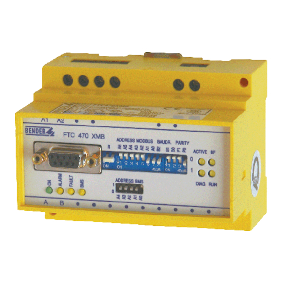
- Page 1 Operating Manual FTC470XMB Protocol converter for the connection of the Bender measuring interface to the Modbus RTU Software version: D143 V2.1x Power in electrical safety TGH1367en/06.2010...
- Page 2 Dipl.-Ing. W. Bender GmbH & Co.KG Londorfer Str. 65 • 35305 Grünberg • Germany Postfach 1161 • 35301 Grünberg • Germany Tel.: +49 (0)6401-807-0 Fax: +49 (0)6401-807-259 © Dipl.-Ing. W. Bender GmbH & Co.KG E-mail: info@bender-de.com Web server: http://www.bender-de.com All rights reserved.
-
Page 3: Table Of Contents
4.2.6 Status indicators for BMS bus and supply voltage ............17 BMS side of the FTC470XMB ....................18 Modbus RTU side of the FTC470XMB — Mode 1 ............. 19 4.4.1 Definition of Mode 1 ........................19 4.4.2 Communication between Modbus RTU and BMS ............19 4.4.3 Setting of the Modbus configuration register .............. - Page 4 4.5.3 Correct time control of the FTC470XDP by Modbus RTU commands is required. 25 4.5.4 FTC470XMB communicate with the Modbus RTU Master as "BMS Slave" ....26 4.5.5 FTC470XMB communicates as the "BMS Master" with the Modbus RTU Master . 26 4.5.6 Communication between Modbus RTU and BMS ............27 5.
- Page 5 8.4.2 Returning the Master function ....................84 Control commands for use in the Master mode ............... 85 8.5.1 Interrogating the FTC470XMB device type ................ 87 Control commands for use in the BMS Slave mode ............88 8.6.1 Requesting the measuring value of all channels of an RCMS470-12 ......89...
- Page 6 Table of Contents 8.6.2 Requesting a device type after taking over the Master function by FTC470XMB 90 8.6.3 Parameter setting after the FTC470XMB has taken over the Master function ..91 9. Service and support ....................93 Damage in transit ........................93 Malfunctions ..........................
-
Page 7: How To Use This Documentation Effectively
Basic application: ● This chapter deals with the normal use of this product. The protocol converter FTC470XMB (gateway): ● This chapter describes the scope of delivery, the operating and display elements available at the device, the function of the protocol converter as well as the intended use. -
Page 8: Brief Instruction
If you are familiar with automation engineering, particularly with the Modbus RTU, it may be helpful to start right away with "Chapter 4. The FTC470XMB protocol converter" and "Chapter 5. Installation". In chapter 4 you will find information about the BMS-Modbus com- munication model including the ID numbers and start addresses required for read and write access. -
Page 9: Safety Instructions
2.2 Intended use The FTC470XMB protocol converter connects the serial Bender BMS bus to the serial Modbus RTU. The converter is capable of transmitting information from the BMS bus to the Modbus RTU and vice versa. -
Page 10: Address Setting And Termination
Safety instructions 2.3 Address setting and termination A prerequisite for proper functioning of the FTC470XMB protocol converter is its correct ad- dress setting and termination. Addresses assigned twice may lead to serious malfunctions in BMS or Modbus RTU systems. Ensure correct address setting and termination of the FTC470XMB. For details refer to the chapter basic configuration on page 31. -
Page 11: Standard Application
BMS. Our protocol converter FTC470XMB (gateway) is intended to connect this BMS interface to the Modbus RTU. For that purpose, the FTC470XMB is connected to the Modbus RTU net- work in the function of a Modbus RTU Slave. Modbus-... -
Page 12: Application Of The Ftc470Xmb
Standard application 3.3 Application of the FTC470XMB The connection of Bender systems to the BMS bus and to the Modbus RTU by means of the FTC470XMB can become necessary for several reasons: A Modbus RTU device is expected to respond to an event in the BMS world. -
Page 13: The Ftc470Xmb Protocol Converter
4. The FTC470XMB protocol converter This chapter describes: the scope of delivery ● the display and operating elements on the device ● the function of the protocol converter (gateways) ● the intended use ● 4.1 Scope of delivery Included are: the FTC470XMB protocol converter ●... -
Page 14: Dip Switch For Modbus Rtu Address Setting
The FTC470XMB protocol converter 4.2.1 DIP switch for Modbus RTU address setting The FTC470XMB must be disconnected from the supply after changing the DIP switch settings. Reconnection to the power supply provides the actual indica- tion of the Modbus RTU status. -
Page 15: Dip Switch For Setting The Baud Rate
The FTC470XMB protocol converter 4.2.2 DIP switch for setting the baud rate Valid baud rates can be set between 1200 bit/s and 57600 bit/s. The standard value for Mod- bus RTU is 19200 bit/s. Setting 0, all DIP switches in position OFF, is invalid and not allowed! BAUDR. -
Page 16: Modbus Rtu Status Indicators
CRC error rate is above 10%. Data exchange is not possible Bus function Green LED lights up: FTC470XMB is connected to the Modbus RTU and is ready for data exchange. Status of DIP switch settings (only Modbus RTU) Status LED red: all Modbus switches are in "OFF"... -
Page 17: Dip Switches For Bms Bus Address Setting
BMS side of the Modbus RTU. Yellow fault lights in case of disturbances on the BMS bus, when an FAULT invalid BMS address has been set and/or in case of FTC470XMB malfunc- tions. Yellow BMS LED shows activities on the BMS bus. -
Page 18: Bms Side Of The Ftc470Xmb
This data is only sent to the bus if requested by BMS commands. Redundant Master function FTC470XMB can be used as a redundant Master. In the event failure of the regular Master (bus address 1) the FTC470XMB takes over the Master function after approximately 60 sec- onds in order to control the BMS bus. -
Page 19: Modbus Rtu Side Of The Ftc470Xmb - Mode 1
BMS instruction codes: 4, 30, 32, 35, 37, 39, 48 and 105 ● FTC470XMB can be operated in Mode 1 or in Mode 2 or even alternately. This is possible since different memory ranges are used for both modes. 4.4.2... - Page 20 The input data (read access) ● of the Modbus Master are also read out from pre-defined read registers of the FTC470XMB. The segment addresses of the read registers are coupled to those of the configuration registers using an offset of 400h. The address range for read accesses is pre-defined as:...
-
Page 21: Setting Of The Modbus Configuration Register
Master function. Please note that some BMS Masters cannot return their Master function! If the FTC470XMB needs to operate as Master in an existing BMS environment, only the fol- lowing devices can temporarily return their Master function: EDS460/461, EDS490/491 software version 2.00 or higher... - Page 22 Use the data format described at the beginning of this chapter to set the register. If the data must be read out of more than 10 BMS devices via FTC470XMB, it is made possible by the programming of the Modbus Master. For this purpose, the Master rewrites the 10 seg- ments of the configuration register defined via their address with the desired BMS instruction codes and BMS addresses.
-
Page 23: Reading Out Of The Bms Data From The Modbus Read Register
The FTC470XMB protocol converter 4.4.4 Reading out of the BMS data from the Modbus read register The BMS data requested by the Modbus Master are read out of a total of 10 segments of the read register: Address ranges of the read register segments 0x0006... - Page 24 Word 5, Low-Byte: BMS data type, like word 3, Low-Byte. The content of the Modbus read register in the FTC470XMB is periodically refreshed. With measured values (BMS instruction codes 4 and 105), the refresh occurs every second; while parameters are refreshed every 5 minutes.
-
Page 25: Modbus Rtu Side Of The Ftc470Xmb - Mode 2
BMS address: 1...150 ● BMS commands: all ● The FTC470XMB is a Modbus RTU Slave. That means that at least one Master must exist on the Modbus RTU side. 4.5.2 Cyclical data exchange In this manual, the Modbus RTU is generally regarded from the Modbus RTU Master’s point of view. -
Page 26: Ftc470Xmb Communicate With The Modbus Rtu Master As "Bms Slave
FTC470XMB communicate with the Modbus RTU Master as "BMS Slave" If a BMS address between 2 and 30 has been assigned to the FTC470XMB, it acts as a BMS Slave. In this case, the Modbus RTU Master can use the following functions:... -
Page 27: Communication Between Modbus Rtu And Bms
The output data (request, write access) ● of the Modbus Master are always written into the same memory section of the FTC470XMB (Modbus Slave). This is done with the Modbus function 16 (writing of several Words). The address is entered in decimal or hexadecimal format depending on the Modbus Master. The... - Page 28 The FTC470XMB protocol converter The input data (read access) ● of the Modbus Master is always read out from the same memory range via the Modbus function 3 (reading of several Words). The address can be entered in decimal or hexadecimal format depending on the Modbus Master.
- Page 29 Format of the output and input data The whole communication is to be regarded from the Modbus Master’s point of view. This Master sends the output data, a Words sequence (2 bytes each), to the FTC470XMB (Modbus RTU Slave). As an answer, the input data is returned as a Words sequence (2 bytes each) to the Modbus Master.
- Page 30 The FTC470XMB protocol converter Format of the input data: Reading from FTC470XMB (= input data of the Modbus RTU Master) Modbus function 3 Word 1 Word 2 Word 3 Word 4 Word 5 H-Byte L-Byte H-Byte L-Byte H-Byte L-Byte H-Byte...
-
Page 31: Installation
– If the FTC470XMB is located at the end of the Modbus RTU, set the switch R to "ON" posi- tion (down position). The terminating resistor is activated. – If the FTC470XMB is not located at the end of the Modbus RTU, set the switch R to up posi- tion. the terminating resistor is deactivated. -
Page 32: Wiring Diagram
J-Y(St)Y 2x0.6 4. If the FTC470XMB is located at the end of the bus, the end of the bus must be terminated with a resistor of 120 Ω. For that purpose loosen the terminals A and B in order to connect the termi- nating resistor in parallel. -
Page 33: Function
The following tables describe the bus communication from the Modbus RTU Master’s point of view. Possible answers from the protocol converter FTC470XMB to the Master’s request are listed in the table below. The following data types are described: Alarm messages ●... -
Page 34: Requesting Alarm Messages
BMS devices and are requested by the BMS Master. Due to the fact that alarm values are rel- evant to safety, they take high priority on the bus. 6.1.1 Number of all alarm messages of a BMS device Writing to FTC470XMB (= output data of the Modbus RTU Master) Word 2 Word 3... -
Page 35: Requesting Alarm Messages Via The Channel Number
Function 6.1.2 Requesting alarm messages via the channel number Writing to FTC470XMB (= output data of the Modbus RTU Master) Word 2 Word 3 Word 4 Word 5 Function Devices channe Data Data „0“ comma „0“ address l No. type... - Page 36 Function Word 2 Word 3 Word 4 Word 5 Function Devices channe Data Data „0“ comma „0“ address l No. type value 107TD47 IZ427 Connection fault CT EDS46x/49x „ 1...12 RCMS460 1...12 RCMS490 1...12 Fault K1 (open circuit, contactor cannot be PRC487 „...
- Page 37 Function Word 2 Word 3 Word 4 Word 5 Function Devices channe Data Data „0“ comma „0“ address l No. type value Start-up of insulation fault location for 1 pass PGH... „ (approx. 5 min.) Start/stop insulation fault location via but- PGH...
- Page 38 Function 107TD47 Insulation fault in Ω „ value IRDH... 1, 2 107TD47 Insulation fault in MΩ „ value IRDH... 1, 2 107TD47 Transformer load in % „ value IZ427 Transformer load < as value in % IZ427 „ value Transformer load > as value in % IZ427 „...
-
Page 39: Requesting Operating Messages
BMS Master via the bus. Some BMS devices (EDS47x) do not provide operating messages, they only provide alarm messages. 6.2.1 Number of all operating messages of a BMS device Writing to FTC470XMB (= output data of the Modbus RTU Master) Word 2 Word 3... -
Page 40: Requesting Operating Messages Via The Channel Number
No. Table 6.7: Master request: request for operating messages via channel number Reading from FTC470XMB (= input data of the Modbus RTU Master) No operating messages (e.g. because of chan- Address alarms) nel No. - Page 41 Function Word 2 Word 3 Word 4 Word 5 Function Devices channe Data Data „0“ comma „0“ address l No. type value RCMS460/ Undercurrent > as value in A „ 1... 12 value LIM2010 „ value LIM2010 „ value EDS46x/49x Residual current >...
-
Page 42: Requesting Measuring Values
105. This function can be used for the purpose of logging. 6.3.1 Requesting measuring values via the channel number Writing to FTC470XMB (= output data of the Modbus RTU Master) Word 2 Word 3... -
Page 43: Taking Over Or Returning The Master Function
Function 6.4 Taking over or returning the Master function Certain commands in a BMS network can only be carried out when the FTC470XMB takes over the Master function. This is required for the parameterization of BMS devices, for example. When BMS address 1 is continuously assigned to the FTC470XMB , taking over of the Master function is not necessary. -
Page 44: Returning The Master Function
Function 6.4.2 Returning the Master function Writing to FTC470XMB (= output data of the Modbus RTU Master) Word 2 Word 3 Word 4 Word 5 Function Devices Chann Data Data „0“ comma „0“ address el No. type value Command to FTC470XMB to return the Mas- ter function in the BMS network. -
Page 45: Parameterization
Function 6.5 Parameterization When the FTC470XMB works in the BMS Slave mode, a temporary Master takeover is re- quired before carrying out the parameterization below! Take into consideration that the Master function must be returned by the FTC470XMB af- ter Master function transfer and the parameterization. - Page 46 Function Word 2 Word 3 Word 4 Word 5 Function Devices Chann Data Data „0“ comma „0“ address el No. type value Fault memory: IRDH.. „ " 0 = off 1 = on Start time self test: IRDH.. „ " 00:00...23:59 EDS mode: 0 = off 1 = on 2 = auto 3 = 1 cycle...
-
Page 47: Setting The Response Values Via Channel Number
Function 6.5.2 Setting the response values via channel number Writing to FTC470XMB (= output data of the Modbus RTU Master Word 2 Word 3 Word 4 Word 5 Function Devices Chann Data Data „0“ comma „0“ address el No. type... - Page 48 „ " Time delay of the alarm relay in s 107TD47 „ " Table 6.17: Master request: setting the response values Reading from FTC470XMB (= input data of the Modbus RTU Master) Chan- Acknowledgement RCMS.. Address value nel No. Invalid value RCMS..
-
Page 49: Requesting The Delay On Response
Function 6.5.3 Requesting the delay on response Writing to FTC470XMB (= output data of the Modbus RTU Master) Word 2 Word 3 Word 4 Word 5 Function Devices Chann Data Data „0“ comma „0“ address el No. type value Request for the delay on response of a RCMS..,... -
Page 50: Requesting The Ct Type
Function 6.5.5 Requesting the CT type Writing to FTC470XMB (= output data of the Modbus RTU Master) Word 2 Word 3 Word 4 Word 5 Function Devices Chann Data Data „0“ comma „0“ address el No. type value Request for the sensor type of a device (CT EDS.. -
Page 51: Requesting The Status Of Ct Monitoring
Function 6.5.7 Requesting the status of CT monitoring Writing to FTC470XMB (= output data of the Modbus RTU Master) Word 2 Word 3 Word 4 Word 5 Function Devices Chann Data Data „0“ comma „0“ address el No. type value Request for the status of CT monitoring of a EDS.., RCMS address... -
Page 52: Requesting The Correction Factor For The Ct Transformation Ratio
Function 6.5.9 Requesting the correction factor for the CT transformation ratio Writing to FTC470XMB (= output data of the Modbus RTU Master) Word 2 Word 3 Word 4 Word 5 Function Devices Chann Data Data „0“ comma „0“ address el No. -
Page 53: Requesting The Fault Memory
Function 6.5.11 Requesting the fault memory Writing to FTC470XMB (= output data of the Modbus RTU Master) Word 2 Word 3 Word 4 Word 5 Function Devices Chann Data Data „0“ comma „0“ address el No. type value EDS.., RCMS..,... -
Page 54: Requesting The Operating Mode Of The Alarm Relay
Function 6.5.13 Requesting the operating mode of the alarm relay Writing to FTC470XMB (= output data of the Modbus RTU Master) Word 2 Word 3 Word 4 Word 5 Function Devices Chann Data Data „0“ comma „0“ address el No. -
Page 55: Requesting The Channel Function
Function 6.5.15 Requesting the channel function Writing to FTC470XMB (= output data of the Modbus RTU Master) Word 2 Word 3 Word 4 Word 5 Function Devices Chann Data Data „0“ comma „0“ address el No. type value Chan- Request for the current function of a channel address nel No. -
Page 56: Requesting The Number Of Measurements Per Channel
Function 6.5.17 Requesting the number of measurements per channel Writing to FTC470XMB (= output data of the Modbus RTU Master) Word 2 Word 3 Word 4 Word 5 Function Devices Chann Data Data „0“ comma „0“ address el No. type... -
Page 57: Requesting The Maximum Number Of Measurements
In EDS systems, the maximum number of measurements can be set in the menu item „Peak“. Setting a higher peak value allows increased measuring reliability in systems where interferences occur, for example caused by converters. Writing to FTC470XMB (= output data of the Modbus RTU Master) Word 2 Word 3... -
Page 58: Requesting Device-Specific Information
Function 6.6 Requesting device-specific information When the FTC470XMB works in the BMS Slave mode, a temporary Master take- over is required before carrying out the parameterization below! Take into consideration that the Master function must be returned by the FTC470XMB after Master function transfer and the parameterization. -
Page 59: Requesting The Software Version
Function 6.6.2 Requesting the software version Writing to FTC470XMB (= output data of the Modbus RTU Master) Word 2 Word 3 Word 4 Word 5 Function Devices Chann Data Data „0“ comma „0“ address el No. type value Request for the software version address Table 6.57: Master request: for the software version... - Page 60 Function Alarm indicator and test combination MK2418C " Word 2 Word 3 Word 4 Word 5 Function Devices Chann Data Data „0“ comma „0“ address el No. type value Converter BMS=> digital outputs MODS480 " Insulation fault test device PGH471 "...
-
Page 61: Control Commands For Use In Bms Master Mode
Function 6.7 Control commands for use in BMS Master mode When the FTC470XMB works in the BMS Slave mode, a temporary Master take- over is required before carrying out the control commands below! Take into consideration that the Master function must be returned by the FTC470XMB after Master function transfer and after the control commands have been carried out. -
Page 62: Starting A Self Test Of Insulation Monitoring Devices
Function 6.7.2 Starting a self test of insulation monitoring devices Writing to FTC470XMB (= output data of the Modbus RTU Master) Word 2 Word 3 Word 4 Word 5 Function Devices Chann Data Data „0“ comma „0“ address el No. -
Page 63: Buzzer Mute
Function 6.7.4 Buzzer mute Writing to FTC470XMB (= output data of the Modbus RTU Master) Word 2 Word 3 Word 4 Word 5 Function Devices Chann Data Data „0“ comma „0“ address el No. type value MK2418.., Buzzer mute address address SMI470…... -
Page 64: Control Commands To Be Used In The Bms Slave Mode
Function 6.8 Control commands to be used in the BMS Slave mode 6.8.1 Starting and stopping EDS systems Writing to FTC470XMB (= output data of the Modbus RTU Master) Word 2 Word 3 Word 4 Word 5 Function Devices Chann... -
Page 65: Output Of Modbus Messages Via The Bms Bus
That allows, for example, the indica- tion of Modbus messages on BMS panels or alarm and operator panels. The FTC470XMB provides a maximum of 12 channels for Modbus messages. Writing to FTC470XMB (= output data of the Modbus RTU Master) - Page 66 Function TGH1367en/06.2010...
-
Page 67: Programming Examples Mode 1
Requesting measured values with status information (instruction code 105) ● A schematic overview is listed first. The process always follows the sequence “setting con- figuration register, reading out read register.” The first 8 register segments of the FTC470XMB are described below in succession: Start addresses instruction Configuration register... -
Page 68: Requesting The Operating Messages Of An Rcms470-12
Programming examples mode 1 7.1 Requesting the operating messages of an RCMS470-12 A Modbus RTU Master is to query the operating messages of all 12 channels (BMS instruction code 4) from an RCMS470-12 with BMS address 5. The Configuration register must be written as follows: Start address BMS instruc- BMS address... -
Page 69: Requesting The Response Values Of An Rcms470-12
Programming examples mode 1 7.2 Requesting the response values of an RCMS470-12 A Modbus RTU Master is to query the defined response values of all 12 channels (BMS in- struction code 30) from an RCMS470-12 with BMS address 5. The Configuration register must be written as follows: Start address BMS instruc- BMS address... -
Page 70: Requesting The Type Of Ct Of An Eds470-12
Programming examples mode 1 7.3 Requesting the type of CT of an EDS470-12 A Modbus RTU Master is to query the defined CT type of all 12 channels (BMS instruction code 32) from an EDS470-12 with BMS address 5. The Configuration register must be written as follows: Start address BMS instruc- BMS address... -
Page 71: Requesting The Correction Factor For Ct Of An Rcms470-12
Programming examples mode 1 7.4 Requesting the correction factor for CT of an RCMS470-12 A Modbus RTU Master is to query the defined correction factor of all 12 channels (BMS in- struct. code 35) for the transformation ratio of a CT from an RCMS470-12 with BMS address 5. The Configuration register must be written as follows: Start address BMS instruc-... -
Page 72: Requesting The Status Of Ct Monitoring Of An Rcms470-12
Programming examples mode 1 7.5 Requesting the status of CT monitoring of an RCMS470-12 A Modbus RTU Master is to query the status of the CT monitoring of all 12 channels (BMS instruction code 37) from an RCMS470-12 with BMS address 5. The Configuration register must be written as follows: Start address BMS instruc-... -
Page 73: Requesting The Channel Functions Of An Rcms470-12
Programming examples mode 1 7.6 Requesting the channel functions of an RCMS470-12 A Modbus RTU Master is to query the channel functions of all 12 channels (BMS instruction code 39) from an RCMS470-12 with BMS address 5. The Configuration register must be written as follows: Start address BMS instruc- BMS address... -
Page 74: Requesting The Response Delay Of An Rcms470-12
Programming examples mode 1 7.7 Requesting the response delay of an RCMS470-12 A Modbus RTU Master is to query the response delay of all 12 channels (BMS instruction code 48) from an RCMS470-12 with BMS address 5. The Configuration register must be written as follows: Start address BMS instruc- BMS address... -
Page 75: Requesting The Measuring Values Of An Rcms470-12
Programming examples mode 1 7.8 Requesting the measuring values of an RCMS470-12 A Modbus RTU Master is to query the measured values including status information of all 12 channels (BMS instruction code 105) from an RCMS470-12 with BMS address 5. The Configuration register must be written as follows: Start address BMS instruc-... - Page 76 Programming examples mode 1 TGH1367en/06.2010...
-
Page 77: Programming Examples Mode 2
All the examples below include 5 Data Words. When programming, take into consideration that the Modbus address of the FTC470XMB as well as the respective Modbus function 16 (write) and 3 (read) is to be put in front of the Data Words. The formats of the output and input data are described on page 29. -
Page 78: Alarm Messages Or Information Via Channel Number
The Modbus RTU Master interrogates BMS address 5, the 107TD47 insulation monitoring de- vice, for information about the overtemperature (alarm message). This message is available at channel 3 of the 107TD47. The Modbus RTU Master sends an appropriate command to FTC470XMB (function 16, output data): Word 1... - Page 79 Programming examples mode 2 The Modbus RTU Master interrogates BMS address 20, an EDS470-12 insulation fault evalu- ator, for information about the alarm value of channel 5: The Modbus RTU Master sends an appropriate command to FTC470XMB (function 16, output data): Word 1...
-
Page 80: Operating Messages
The Modbus RTU Master addresses BMS address 25, the control device PRC487, for informa- tion about the state of Line 1 (operating message. This information is available at channel 1. The Modbus RTU Master sends an appropriate command to FTC470XMB (function 16, output data):... - Page 81 The Modbus RTU Master addresses BMS address 29, 107TD47, for information about the ac- tual load of the transformer (operating message). This value is available at channel 2 of the device: The Modbus RTU Master sends an appropriate command to FTC470XMB (function 16, output data): Word 1...
-
Page 82: Measuring Values, With Regard To The Channels
The Modbus RTU Master addresses BMS address 7, the RCMS470-12 residual current monitor, for information about the actual measuring value. This value is available at channel 10. The Modbus RTU Master sends an appropriate command to FTC470XMB (function 16, output data):... - Page 83 The Modbus RTU Master addresses BMS address 20, the insulation monitoring device 107TD47, for the actual measuring value. This information is available at channel 1 of the 107TD47: The Modbus RTU Master sends an appropriate command to FTC470XMB (function 16, output data): Word 1...
-
Page 84: Temporary Master Takeover And Return
Master function. This is required for the parameterization of BMS devices, for ex- ample. When BMS address 1 is continuously assigned to the FTC470XMB , taking over of the Master function is not necessary. The FTC470XMB must take over the Master function in case of parameter re-... -
Page 85: Control Commands For Use In The Master Mode
Programming examples mode 2 8.5 Control commands for use in the Master mode For the control commands in the tables below the FTC470XMB is required to take over the Master function or must already be in this mode. The Modbus RTU Master deletes all existing alarm messages of all the devices connected to... - Page 86 Programming examples mode 2 The Modbus RTU Master deletes all alarm messages of an RCMS470-12 residual current eval- uator with address 10: The Modbus RTU Master sends an appropriate command to FTC470XMB (function 16, output data): Word 1 Word 2...
-
Page 87: Interrogating The Ftc470Xmb Device Type
8.5.1 Interrogating the FTC470XMB device type For fault finding or commissioning, the following example can be helpful. The device type of the protocol converter FTC470XMB with address 1 (= Master) is to be interrogated. The Modbus RTU Master interrogates FTC470XMB... -
Page 88: Control Commands For Use In The Bms Slave Mode
EDS system in POSITION mode. The value to be requested is available at chan- nel 3 with BMS address 7. FTC470XMB is in the Slave mode during the whole process: The Modbus RTU Master sends an appropriate command to FTC470XMB... -
Page 89: Requesting The Measuring Value Of All Channels Of An Rcms470-12
The actual measuring values of all 12 channels of an RCMS470-12 with address 12 are to be interrogated. For that purpose the Modbus RTU Master at first interrogates channel 1 (output data): The Modbus RTU Master sends an appropriate command to FTC470XMB (function 16, output data): Word 1... -
Page 90: Requesting A Device Type After Taking Over The Master Function By Ftc470Xmb
The following example shows the Master takeover, the subsequent interrogation and Master return. In this example it is assumed that BMS address 2 is assigned to FTC470XMB 2. By assigning BMS address 1 to the FTC470XMB, it would anyway have the Master function. -
Page 91: Parameter Setting After The Ftc470Xmb Has Taken Over The Master Function
The examples below show the taking over of the Master function, the subsequent activity and the Master return. All the examples are based on the assumption that the BMS address of the FTC470XMB is 2. By assigning BMS address 1 to the FTC470XMB, it would anyway have the Master function. - Page 92 The channels 11 and 12 of a residual current evaluator RCMS470-12 with address 10 are to be switched off because they are not used. In this way the measuring time of the devices can be reduced. At first, the Modbus RTU Master instructs the FTC470XMB to take over the Mas- ter function...
-
Page 93: Service And Support
Dipl.-Ing. W. Bender GmbH&Co.KG Londorfer Straße 65 35305 Grünberg +49(0)6401/807-0 9.2 Malfunctions If the FTC470XMB leads to malfunctions in the connected system, please refer to the accom- panying technical manual. 9.2.1 What shall be checked? Check whether ... the device is supplied by the correct supply voltage U ●... -
Page 94: Warranty And Liability
Service and support sent to Bender within the warranty period. The qualifying conditions are that Bender shall recognize this product as being faulty, and that the fault cannot be attributed to improper handling or modification of the device, nor to abnormal operating conditions. -
Page 95: Technical Data
10. Technical data 10.1 Technical data in tabular form The values marked with * are absolute values Insulation coordination acc. to IEC 60664-1 Rated voltage................................. AC 250 V Rated impulse voltage/pollution degree........................ 4 kV / 3 Voltage ranges Supply voltage U (see nameplate) ...................... -
Page 96: Dimension Diagram
Ambient temperature, during operation....................-25 °C...+70 °C Ambient temperature (storage)........................ -40 °C...+85 °C Screw mounting................................ 2 x M4 10.2 Dimension diagram FTC470XMB is incorporated in a Bender enclosure of the X470 series, as described below. 99 mm ø 4,3 mm 91 mm ø... - Page 97 - as BMS Slave 26 messages of all the devices Address ranges, Modbus 27 connected to the bus 85 address setting Device type of the FTC470XMB, - BMS 31 How to use this documentation requesting 87 - Modbus RTU 31...
- Page 98 PEAK, setting 57 Work activities on electrical in- stallations 9 PRC487 Master function, temporarily - state of Line 1, requesting Master return by FTC470XMB Programming examples - Mode 1 67 Master takeover by FTC470XMB - Mode 2 77 Maximum number of measure- ments(PEAK), requesting RCMS4...
- Page 100 Dipl.-Ing. W. Bender GmbH & Co. KG Londorfer Str. 65 • 35305 Grünberg • Germany Postfach 1161 • 35301 Grünberg • Germany Tel.: +49 6401 807-0 Fax: +49 6401 807-259 E-Mail: info@bender-de.com Web server: http://www.bender-de.com...
Need help?
Do you have a question about the FTC470XMB and is the answer not in the manual?
Questions and answers