Sign In
Upload
Manuals
Brands
Bender Manuals
Media Converter
FTC470XMB
Bender FTC470XMB Manuals
Manuals and User Guides for Bender FTC470XMB. We have
1
Bender FTC470XMB manual available for free PDF download: Operating Manual
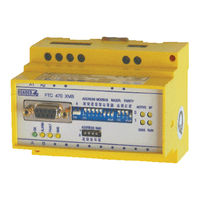
Bender FTC470XMB Operating Manual (100 pages)
Protocol converter for the connection of the Bender measuring interface to the Modbus RTU
Brand:
Bender
| Category:
Media Converter
| Size: 1.24 MB
Table of Contents
Table of Contents
3
1 How to Use this Documentation Effectively
7
About the Operating Manual
7
Overview of the Individual Chapters
7
Brief Instruction
8
2 Safety Instructions
9
Work Activities on Electrical Installations
9
Intended Use
9
Address Setting and Termination
10
Setting of the DIP Switches for Modbus RTU
10
3 Standard Application
11
Bus Interface
11
Modbus RTU
11
Application of the FTC470XMB
12
Restrictions
12
4 The FTC470XMB Protocol Converter
13
Scope of Delivery
13
Display and Operating Elements
13
DIP Switch for Modbus RTU Address Setting
14
DIP Switch for Setting the Baud Rate
15
DIP Switches for Modbus RTU Parity
15
Modbus RTU Status Indicators
16
DIP Switches for BMS Bus Address Setting
17
Status Indicators for BMS Bus and Supply Voltage
17
BMS Side of the FTC470XMB
18
Modbus RTU Side of the FTC470XMB - Mode 1
19
Definition of Mode 1
19
Communication between Modbus RTU and BMS
19
Setting of the Modbus Configuration Register
21
Reading out of the BMS Data from the Modbus Read Register
23
Modbus RTU Side of the FTC470XMB - Mode 2
25
Definition of the Mode 2
25
Cyclical Data Exchange
25
Correct Time Control of the FTC470XDP by Modbus RTU Commands Is Required
25
FTC470XMB Communicate with the Modbus RTU Master as "BMS Slave
26
FTC470XMB Communicates as the "BMS Master" with the Modbus RTU Master
26
Communication between Modbus RTU and BMS
27
5 Installation
31
Basic Configuration
31
Mounting and Connection of the Device
31
Wiring Diagram
32
6 Function
33
Requesting Alarm Messages
34
Number of All Alarm Messages of a BMS Device
34
Requesting Alarm Messages Via the Channel Number
35
Requesting Operating Messages
39
Number of All Operating Messages of a BMS Device
39
Requesting Operating Messages Via the Channel Number
40
Requesting Measuring Values
42
Requesting Measuring Values Via the Channel Number
42
Taking over or Returning the Master Function
43
Taking over the Master Function
43
Returning the Master Function
44
Parameterization
45
Requesting the Response Values Via Channel Number
45
Setting the Response Values Via Channel Number
47
Requesting the Delay on Response
49
Setting the Delay on Response
49
Requesting the CT Type
50
Setting the CT Type
50
Requesting the Status of CT Monitoring
51
Setting the Status of CT Monitoring
51
Requesting the Correction Factor for the CT Transformation Ratio
52
Setting the Correction Factor for CT Transformation Ratio
52
Requesting the Fault Memory
53
Setting the Fault Memory
53
Requesting the Operating Mode of the Alarm Relay
54
Setting the Operating Mode of the Alarm Relay
54
Requesting the Channel Function
55
Setting the Channel Function
55
Requesting the Number of Measurements Per Channel
56
Setting the Number of Measurements Per Channel
56
Requesting the Maximum Number of Measurements
57
Setting the Maximum Number of Measurements
57
Requesting Device-Specific Information
58
Requesting Fault Messages after a Self Test
58
Requesting the Software Version
59
Requesting the Device Type and Device Version
59
Control Commands for Use in BMS Master Mode
61
Deleting All Alarm Messages
61
Starting a Self Test of Insulation Monitoring Devices
62
Starting the Self Test of an EDS System
62
Buzzer Mute
63
Switching the Relay of a Specific Channel
63
Control Commands to be Used in the BMS Slave Mode
64
Starting and Stopping EDS Systems
64
Output of Modbus Messages Via the BMS Bus
65
7 Programming Examples Mode 1
67
Requesting the Operating Messages of an RCMS470-12
68
Requesting the Response Values of an RCMS470-12
69
Requesting the Type of CT of an EDS470-12
70
Requesting the Correction Factor for CT of an RCMS470-12
71
Requesting the Status of CT Monitoring of an RCMS470-12
72
Requesting the Channel Functions of an RCMS470-12
73
Requesting the Response Delay of an RCMS470-12
74
Requesting the Measuring Values of an RCMS470-12
75
8 Programming Examples Mode 2
77
Alarm Messages
77
Number of Alarm Messages
77
Alarm Messages or Information Via Channel Number
78
Operating Messages
80
Measuring Values, with Regard to the Channels
82
Temporary Master Takeover and Return
84
Taking over the Master Function
84
Returning the Master Function
84
Control Commands for Use in the Master Mode
85
Interrogating the FTC470XMB Device Type
87
Control Commands for Use in the BMS Slave Mode
88
Requesting the Measuring Value of All Channels of an RCMS470-12
89
Requesting a Device Type after Taking over the Master Function by FTC470XMB
90
Parameter Setting after the FTC470XMB Has Taken over the Master Function
91
9 Service and Support
93
Damage in Transit
93
Malfunctions
93
What Shall be Checked
93
Where Do You Get Help
93
Warranty Claims
93
Warranty and Liability
94
10 Technical Data
95
Technical Data in Tabular Form
95
Dimension Diagram
96
Ordering Details
96
Advertisement
Advertisement
Related Products
Bender FTC470XET
Bender FTC470XDP
Bender FP200
Bender FP200W
Bender Categories
Measuring Instruments
Monitor
Control Unit
Control Panel
Relays
More Bender Manuals
Login
Sign In
OR
Sign in with Facebook
Sign in with Google
Upload manual
Upload from disk
Upload from URL