
Related Manuals for Bender FTC470XDP


Summary of Contents for Bender FTC470XDP
- Page 1 Manual FTC470XDP Protocol converter for the connection of the Bender Measuring interface to the PROFIBUS DP Software version: D143 V2.1x FTC470XDP_D00111_00_M_XXEN/02.2015...
- Page 2 Bender GmbH & Co. KG © Bender GmbH & Co. KG All rights reserved. P.O. Box 1161 • 35301 Gruenberg • Germany Londorfer Straße 65 • 35305 Gruenberg • Germany Reprinting only with permission Tel.: +49 6401 807-0 • Fax: +49 6401 807-259 of the publisher.
-
Page 3: Table Of Contents
4.4.2 Correct time control of the FTC470XDP by PROFIBUS commands is required ............................ 16 4.4.3 FTC470XDP communicates with the PROFIBUS DP Master as ’BMS Slave’ ..17 4.4.4 The FTC470XDP communicates as the ’BMS Master’ with the PROFIBUS DP Master ............................18 4.4.5 Format of output and input data .................. - Page 4 Table of Contents 6. Function ......................... 27 GSD file for the PROFIBUS DP Master ................27 Function lists ........................... 27 Requesting alarm messages ....................28 6.3.1 Number of all alarm messages of a BMS device ............28 6.3.2 Requesting alarm messages via the channel number ..........29 Requesting operating messages ..................
- Page 5 7.6.1 Requesting the measuring value of all channels of an RCMS470-12 ....69 7.6.2 Requesting a device type after taking over the Master function by FTC470XDP ..........................70 7.6.3 Parameter setting after the FTC470XDP has taken over the Master function 71 8. Service and support ..................... 73 Damage in transit ........................73 Malfunctions ...........................
- Page 6 Table of Contents Ordering details ........................76 Certification ..........................76 INDEX ........................... 77 FTC470XDP_D00111_00_M_XXEN/02.2015...
-
Page 7: How To Use This Documentation Effectively
Function: This chapter provides information about the device data file GSD includes a summary of all PROFIBUS-DP commands that are transmitted to the FTC470XDP converter. Programming examples: This chapter contains various programming examples which are intended to help you to configure the FTC470XDP. -
Page 8: Brief Instruction
If you are familiar with automation engineering, particularly with the PROFIBUS DP, it may be helpful to start right away with chapter "4. The FTC470XDP protocol converter" and chapter "5. Installation". In chapter 4 you will find information about the BMS-PROFIBUS DP communication model including the ID numbers and start addresses required for read and write access. -
Page 9: Safety Instructions
A prerequisite for proper functioning of the FTC470XDP protocol converter is its correct address set- ting and termination. Addresses assigned twice may lead to serious malfunctions in BMS or PROFIBUS-DP systems. Ensure correct address setting and termination of the FTC470XDP. For details refer to the chapter ba- sic configuration on page 23. FTC470XDP_D00111_00_M_XXEN/02.2015... - Page 10 Safety instructions FTC470XDP_D00111_00_M_XXEN/02.2015...
-
Page 11: Standard Application
Bender Measuring Interface BMS. Our protocol converter FTC470XDP (gateway) is intended to connect this BMS interface to the PROFIBUS DP. For that purpose, the FTC470XDP is connected to the PROFIBUS DP network in the function of a PROFIBUS DP slave. -
Page 12: Application Of The Ftc470Xdp
Standard application 3.2 Application of the FTC470XDP The connection of Bender systems to the BMS bus and to the PROFIBUS DP by means of the FTC470XDP can become necessary for several reasons: A PROFIBUS DP device is expected to respond to an event in the BMS world. -
Page 13: The Ftc470Xdp Protocol Converter
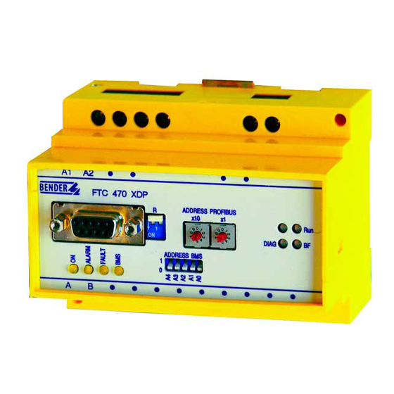
4. The FTC470XDP protocol converter This chapter describes: the scope of delivery the display and operating elements on the device the function of the protocol converter the intended use 4.1 Scope of delivery Included are: the FTC470XDP protocol converter ... -
Page 14: Profibus Dp Status Indicators
BMS side via the PROFIBUS DP. Yellow fault LED lights in case of disturbances on the BMS bus, e.g. when FAULT an invalid BMS address has been set and/or in case of FTC470XDP mal- functions. Yellow BMS LED indicates activities on the BMS bus. -
Page 15: Bms Side Of The Ftc470Xdp
This data is only be sent to the bus if requested by BMS commands. Redundant Master function FTC470XDP can be worked as a redundant Master. In the event failure of the regular Master (bus ad- dress 1) the FTC470XDP takes over the Master function after approximately 60 seconds in order to control the BMS bus. -
Page 16: Profibus Dp Side Of The Ftc470Xdp
The FTC470XDP protocol converter 4.4 PROFIBUS DP side of the FTC470XDP The FTC470XDP is a PROFIBUS DP slave in accordance with EN 50170. That means that at least one Master must exist on the PROFIBUS side. FTC470XDP = PROFIBUS DP slave ... -
Page 17: Ftc470Xdp Communicates With The Profibus Dp Master As 'Bms Slave
FTC470XDP communicates with the PROFIBUS DP Master as ’BMS Slave’ If a BMS address between 2 and 30 has been assigned to the FTC470XDP, it acts as a BMS Slave. In this case, the PROFIBUS DP Master can use the following functions:... -
Page 18: The Ftc470Xdp Communicates As The 'Bms Master' With The Profibus Dp Master
PROFIBUS DP Master Once the BMS address 1 is assigned to the FTC470XDP, the device acts as the BMS Master. In this way it can act as Master in all BMS systems. In addition to the interrogation of alarm and operating mes- sages, it is also possible to set switching commands and parameters. -
Page 19: Format Of Output And Input Data
The communication process is regarded from the PROFIBUS DP’s point of view. The PROFIBUS DP Master sends the output data, a byte sequence, to the FTC470XDP (the PROFIBUS Slave). As an an- swer, the input data is returned as a byte sequence to the PROFIBUS DP Master. As already explained before, the assignment of input bytes and output bytes, i.e. - Page 20 The FTC470XDP protocol converter Format of input data: Byte 1 Byte 2 Byte 3 Byte 4 Byte 5 Byte 6 Byte 7 Byte 8 Consecutive BMS address of Channel number always Com- Type of data High byte Low byte ID number of...
-
Page 21: Intended Use
The FTC470XDP protocol converter 4.5 Intended use The FTC470XDP protocol converter connects the serial Bender BMS bus to the serial PROFIBUS DP. The converter is capable of transmitting information from the BMS bus to the PROFIBUS DP and vice versa. - Page 22 The FTC470XDP protocol converter FTC470XDP_D00111_00_M_XXEN/02.2015...
-
Page 23: Installation
5. Installation 5.1 Basic configuration Before installing the FTC470XDP, an address must be assigned to it. The BMS bus and the PROFIBUS DP must also be provided with an address. Double assignment of addresses may lead to serious malfunctions in the BMS or PROFIBUS DP networks concerned. -
Page 24: Mounting And Connection Of The Device
– If the FTC470XDP is located at the end of the PROFIBUS DP, set the switch R to position "ON" (down position). The terminating resistor is activated. – If the FTC470XDP is not located at the end of the PROFIBUS DP, set the switch R to the up position. The terminating resistor is deactivated 5.2 Mounting and connection of the device... -
Page 25: Wiring Diagram
Installation 5.2.1 Wiring diagram Fig. 5.1: wiring diagram FTC470XDP FTC470XDP_D00111_00_M_XXEN/02.2015... - Page 26 Installation FTC470XDP_D00111_00_M_XXEN/02.2015...
-
Page 27: Function
6.2 Function lists The following tables describe the bus communication from the PROFIBUS Master is point of view. Possible answers from the protocol converter FTC470XDP to the Master is request are listed in the table below. The following data types are described: Alarm messages ... -
Page 28: Requesting Alarm Messages
Value Request for the current number of alarm messages Table 6.1: Master request: number of alarm messages Reading from FTC470XDP (= input data of the PROFIBUS Master) No device with such an address available No alarm messages Number of alarm messages... -
Page 29: Requesting Alarm Messages Via The Channel Number
Requests for alarm messages or information via Channel channel number Table 6.3: Master request: requests for alarm messages or information via channel number Reading from FTC470XDP (= input data of the PROFIBUS Master): Channel No alarm MK2418-11 Insulation fault in the IT system... - Page 30 Function Channel Data Data Function Devices command Type Value 107TD47 IZ427 Connection fault CT EDS46x/49x 1…12 RCMS460 1…12 RCMS490 1…12 Fault K1 (open circuit, contactor can’t be switched PRC487 Fault K2 (open circuit, contactor can’t be switched PRC487 MK2418-11 Control fault SMI470-9 Failure switching element K1 respectively Q1 PRC487...
- Page 31 Function Channel Data Data Function Devices command Type Value RCMS460/ 9…12 Overcurrent < as value in [mA] RCMS490-D4 value CMS460 1…12 RCMS460/ 9…12 Overcurrent > as value in [mA] RCMS490-D4 value CMS460 1…12 Overcurrent in mA 1… 12 value Overcurrent in A 1…...
-
Page 32: Requesting Operating Messages
BMS Master via the bus. Some BMS devices (EDS47x) do not provide operating messages, they only provide alarm messages. 6.4.1 Number of all operating messages of a BMS device Writing to FTC470XDP (= output data of the PROFIBUS Master) Channel Data Data... -
Page 33: Requesting Operating Messages Via The Channel Number
Requesting for operating messages or information channel about the channel number Table 6.7: Master request: requesting the operating messages via the channel number Reading from FTC470XDP (= input data of the PROFIBUS Master) channel No operating messages (e.g. because of alarms) Relay not connected SMO…... - Page 34 Function Channel Data Data Function Devices command Type Value Overcurrent in A value Overcurrent > as value in A value RCMS460/ Undercurrent in mA 1… 12 value RCMS460/ Undercurrent in A 1… 12 value RCMS460/ Undercurrent < as value in mA 1…12 value RCMS460/...
-
Page 35: Requesting Measuring Values
Table 6.9: Master request: requesting the operating messages via the channel number Reading from FTC470XDP (= input data of the PROFIBUS Master) All alarm and operating messages listed in table 6.3 on page 29 "Requests for alarm messages via channel... -
Page 36: Taking Over Or Returning The Master Function
Function 6.6 Taking over or returning the Master function Certain commands in a BMS network can only be carried out when the FTC470XDP takes over the Master function. This is required for the parameterization of BMS devices, for example. When BMS address 1 is continuously assigned to the FTC470XDP , taking over of the Master function is not necessary. -
Page 37: Parameterization
Function 6.7 Parameterization When the FTC470XDP works in the BMS Slave mode, a temporary Master takeo- ver is required before carrying out the parameterization below! Take into consideration that the Master function must be returned by the FTC470XDP after Master function transfer and the parameterization. - Page 38 Function Channel Data Data Function Devices comma Type Value EDS mode: 0 = off 1 = on 2 = auto 3 = 1 cycle IRDH.. value 4 = position EDS operation, IRDH.. " system: 0 = DC 1 = AC 2 = 3AC EDS pulse: 0 = 1mA 1 = 2,5 mA 2 = 10 mA IRDH..
-
Page 39: Setting The Response Values Via Channel Number
Function 6.7.2 Setting the response values via channel number Writing to FTC470XDP (= output of the PROFIBUS Master) Channel Data Data Function Devices comma Type Value Response value, residual current in mA, RCMS…. 1… 12 value range: 1…20000 mA Response value, residual current in A, RCMS…. - Page 40 Response value load current in A 107TD47 " Time delay of the alarm relay in s 107TD47 " Table 6.17: Master request: setting the response values Reading from FTC470XDP (= input data of the PROFIBUS Master) chan- Acknowledgement RCMS… value nel No Invalid value RCMS…...
-
Page 41: Requesting The Delay On Response
Request for the delay on response of a device RCMS…., 1… 12 Table 6.19: Master request: requesting the delay on response Reading from FTC470XDP (= input data of the PROFIBUS Master) Delay on response in ms RCMS…., 1… 12 value No more channels RCMS….,... -
Page 42: Requesting The Ct Type
Request for the sensor type of a device (CT type) EDS… 1… 12 Table 6.23: Master request: request for the sensor type Reading from FTC470XDP (= input data of the PROFIBUS Master) Standard CT (W0..W5 /-S-P, WR) EDS… 1… 12 Split core transformer WS EDS…... -
Page 43: Requesting The Status Of Ct Monitoring
Request for the status of CT monitoring of a device EDS…, 1… 12 channel RCMS… Table 6.27: Master request: status of CT monitoring Reading from FTC470XDP (= input data of the PROFIBUS Master) EDS…, CT monitoring activated 1… 12 RCMS… EDS…, CT monitoring deactivated 1…... -
Page 44: Requesting The Correction Factor For The Ct Transformation Ratio
Requesting the correction factor for the CT transfor- RCMS… 1… 12 mation ratio via channel number Table 6.31: Master request: correction factor for CT transformation ratio Reading from FTC470XDP (= input data of the PROFIBUS Master) Multiplication with correction factor, RCMS… 1… 12 value... -
Page 45: Requesting The Fault Memory
PRC470, Request for the status of the fault memory PRC487, MK2418.., SMI.. Table 6.35: Master request: status of the fault memory Reading from FTC470XDP (= input data of the PROFIBUS Master) EDS.., RCMS.., PRC470, Fault memory ON PRC487, MK2418.., SMI.. -
Page 46: Requesting The Operating Mode Of The Alarm Relay
Request for the operating mode of the collective EDS.., RCMS.., alarm relay PRC470… Table 6.39: Master request: operating mode of the collective alarm relay Reading from FTC470XDP (= input data of the PROFIBUS Master) EDS.., RCMS.., N/O operation PRC470… N/C operation "... -
Page 47: Requesting The Channel Function
Value channel Request for the current function of a channel Table 6.43: Master request: request for a channel’s function Reading from FTC470XDP (= input data of the PROFIBUS Master) Overcurrent monitoring, residual current monitoring RCMS… 1… 12 Undercurrent monitoring, open circuit RCMS…... -
Page 48: Requesting The Number Of Measurements Per Channel
Value Request for the number of measurements per channel EDS… 1… 12 Table 6.47: Master request: number of measurements per channel Reading from FTC470XDP (= input data of the PROFIBUS Master) quan- Number of measurements per channel EDS… 1… 12 tity Table 6.48: FTC reply to: number of measurements per channel... -
Page 49: Requesting The Maximum Number Of Measurements
1… 12 Request for the maximum number of measurements PRC470 1… 12 Table 6.51: Master request: the maximum number of measurements Reading from FTC470XDP (= input data of the PROFIBUS Master) EDS…, 1… 12 quan- Preset max. number of measurements PRC470 1…... -
Page 50: Requesting Device-Specific Information
Function 6.8 Requesting device-specific information When the FTC470XDP works in the BMS Slave mode, a temporary Master takeo- ver is required before carrying out the parameterization below! Take into consideration that the Master function must be returned by the FTC470XDP after Master function transfer and the parameterization. -
Page 51: Requesting The Device Type And Device Version
Request for the device type. The answer includes the device family [enclosure/variant] Table 6.59: Master request: for the device type and device variant Reading from FTC470XDP (= input data of the PROFIBUS Master) Device type A-ISOMETER for medical locations acc. to DIN VDE 0107... -
Page 52: Control Commands For Use In Bms Master Mode
Function 6.9 Control commands for use in BMS Master mode When the FTC470XDP works in the BMS Slave mode, a temporary Master takeo- ver is required before carrying out the control commands below! Take into consideration that the Master function must be returned by the FTC470XDP after Master function transfer and after the control commands have been carried out. -
Page 53: Starting The Self Test Of An Eds System
Type Value Starting the self test of an EDS system EDS.., RCMS.. Table 6.65: Master request: starting the self test of an EDS system Reading from FTC470XDP (= input data of the PROFIBUS Master): EDS…, No answer RCMS… EDS… effec-... -
Page 54: Switching The Relay Of A Specific Channel
Switching off the relay of a specific channel " 1… 12 Switching off all relays " 1… 12 Table 6.69: Master request: switching relays of a specific channel Reading from FTC470XDP (= input data of the PROFIBUS Master): No answer SMO481 1… 12 Acknowledgement " 1… 12 Table 6.70: FTC reply to: switching relays of a certain channel... -
Page 55: Control Commands To Be Used In The Bms Slave Mode
Table 6.71: Master request: BMS Master is intended to control the EDS system * The value "address" consists of : "Address" = (BMS address x 100) + channel number Reading from FTC470XDP (= input data of the PROFIBUS Master): No answer data... -
Page 56: Output Of Profibus Messages Via The Bms Bus
That allows, for example, the indication of PROFIBUS messages on BMS panels or alarm and operator panels. The FTC470XDP provides a maximum of 12 channels for PROFIBUS messages. 6.11.1 Output of PROFIBUS alarm messages via BMS bus... -
Page 57: Programming Examples
Necessary configuration data for the PRODFIBUS DP are to be communicated to the PROFIBUS-Mas- ter by means of gsd file ftc_1003.gsd before the program is executed. You can load the current file under the following address: http://www.bender-de.com => Download/Software 7.1 Alarm messages 7.1.1... -
Page 58: Requesting Alarm Messages Or Information Via Channel Number
Programming examples 7.1.2 Requesting alarm messages or information via channel number The PROFIBUS Master interrogates BMS address 5, the 107TD47 insulation monitoring device, for in- formation about the overtemperature (alarm message). This message is available at channel 3 of the 107TD47: PROFIBUS Master output data: Byte 1... - Page 59 Programming examples The PROFIBUS Master interrogates BMS address 20, an EDS470-12 insulation fault evaluator, for in- formation about the alarm value of channel 5: PROFIBUS Master output data: Byte 1 Byte 2 Byte 3 Byte 4 Byte 5 Byte 6 Byte 7 Byte 8 Consecutive...
-
Page 60: Operating Messages
Programming examples 7.2 Operating messages 7.2.1 Requesting the operating messages via channel number The PROFIBUS Master addresses BMS address 25, the control device PRC487, for information about the state of Line 1 (operating message. This information is available at channel 1. PROFIBUS Master output data: Byte 1 Byte 2... - Page 61 Programming examples The PROFIBUS Master addresses BMS address 29, 107TD47, for information about the actual load of the transformer (operating message). This value is available at channel 2 of the device: PROFIBUS Master output data: Byte 1 Byte 2 Byte 3 Byte 4 Byte 5 Byte 6...
-
Page 62: Requesting The Measuring Values Via Channel Number
Programming examples 7.3 Requesting the measuring values via channel number The following examples only differ in their replies. The PROFIBUS Master addresses BMS address 7, the RCMS470-12 residual current monitor, for infor- mation about the actual measuring value. This value is available at channel 10. PROFIBUS Master output data: Byte 1 Byte 2... - Page 63 Programming examples The PROFIBUS Master addresses BMS address 20, the insulation monitoring device 107TD47, for the actual measuring value. This information is available at channel 1 of the 107TD47. PROFIBUS Master output data: Byte 1 Byte 2 Byte 3 Byte 4 Byte 5 Byte 6 Byte 7...
-
Page 64: Temporary Master Takeover And Return
Programming examples 7.4 Temporary Master takeover and return Certain commands in a BMS network can only be carried out when the FTC470XDP takes over the Master function. This is required for the parameterization of BMS devices, for example. When BMS address 1 is continuously assigned to the FTC470XDP , taking over of the Master function is not necessary. -
Page 65: Control Commands For Use In The Master Mode
Programming examples 7.5 Control commands for use in the Master mode For the control commands in the tables below the FTC470XDP is required to take over the Master function or must already be in this mode. The PROFIBUS Master deletes all existing alarm messages of all the devices connected to the bus. - Page 66 Programming examples The PROFIBUS Master deletes all alarm messages of an RCMS470-12 residual current evaluator with address 10. PROFIBUS Master output data: Byte 1 Byte 2 Byte 3 Byte 4 Byte 5 Byte 6 Byte 7 Byte 8 Consecutive BMS address of High byte Low byte always...
-
Page 67: Interrogating The Ftc470Xdp Device Type
7.5.1 Interrogating the FTC470XDP device type For fault finding or commissioning, the following example can be helpful. The device type of the protocol converter FTC470XDP with address 1 (= Master) is to be interrogated. PROFIBUS Master output data: Byte 1... -
Page 68: Control Commands For Use In The Bms Slave Mode
Programming examples 7.6 Control commands for use in the BMS Slave mode For carrying out the control commands below, the FTC470XDP is not required to take over the Mas- ter function. The PROFIBUS Master instructs a random Master in a BMS network to start insulation fault location in an EDS system. -
Page 69: Requesting The Measuring Value Of All Channels Of An Rcms470-12
Programming examples 7.6.1 Requesting the measuring value of all channels of an RCMS470-12 The actual measuring values of all 12 channels of an RCMS470-12 with address 12 are to be interro- gated. For that purpose the PROFIBUS-Master at first interrogates channel 1 (output data): Byte 1 Byte 2 Byte 3... -
Page 70: Requesting A Device Type After Taking Over The Master Function By
The following example shows the Master takeover, the subsequent interrogation and Master return. In this example it is assumed that BMS address 2 is assigned to FTC470XDP 2. By assigning BMS ad- dress 1 to the FTC470XDP, it would anyway have the Master function. -
Page 71: Ftc470Xdp
The examples below show the taking over of the Master function, the subsequent activity and the Master return. All the examples are based on the assumption that the BMS address of the FTC470XDP is 2. By assigning BMS address 1 to the FTC470XDP, it would anyway have the Master function. - Page 72 The channels 11 and 12 of a residual current evaluator RCMS470-12 with address 10 are to be switched off because they are not used. In this way the measuring time of the devices can be re- duced. At first, the PROFIBUS Master instructs the FTC470XDP to take over the Master function (output data):...
-
Page 73: Service And Support
8. Service and support 8.1 Damage in transit Damage in transit must be confirmed directly by the carrier. In case of doubt, please inform Bender immediately: Dipl.-Ing. W. Bender GmbH & Co. KG Londorfer Straße 65 35305 Grünberg +49 6401 807-0 8.2 Malfunctions... -
Page 74: Warranty Claims
Service and support 8.3 Warranty claims Bender warrants the FTC470XDP to be free from defects in material and workmanship under normal use and service for a period of 24 months from the date of delivery. This warranty does not extend to any kind of maintenance work and shall only be valid for the first purchaser and shall not extend to products or individual parts thereof which have not been correctly used, or which have undergone modifications. -
Page 75: Technical Data
9. Technical Data 9.1 Technical data in tabular form The values marked with * are absolute values Insulation coordination acc. to IEC 60664-1 Rated voltage................................. AC 250 V Rated impulse voltage/pollution degree........................ 4 kV / 3 Voltage ranges Supply voltage (see nameplate) ..................... AC/DC 85…276 V .............................. -
Page 76: Dimension Diagram
Ambient temperature, during operation....................-25 °C…+70 °C Ambient temperature (storage)......................-40 °C…+85 °C Screw mounting................................ 2 x M4 9.2 Dimension diagram FTC470XDP is incorporated in a Bender enclosure of the X470 series, as described below Possible is: DIN rail mounting according to IEC 60715 ... - Page 77 - Response value, insulation fault lo- Alarm messages, requesting 28 cation, requesting 37 Alarm relay, changing the operating mode Master return by FTC470XDP 64 Master takeover by FTC470XDP 64 Alarm relay, requesting and setting the Maximum number of measure- operating mode 46...
- Page 78 Status indicators, BMS bus 14 status indicators, PROFIBUS DP 14 support and service 73 Temporary taking over of the Master func- tion 17 Warranty and liability 74 Warranty claims 74 wiring diagram FTC470XDP 25 Work activities on electrical installations 9 FTC470XDP_D00111_00_M_XXEN/02.2015...
- Page 80 Bender GmbH & Co. KG P.O. Box 1161 • 35301 Gruenberg • Germany Londorfer Straße 65 • 35305 Gruenberg • Germany Tel.: +49 6401 807-0 • Fax: +49 6401 807-259 E-mail: info@bender.de • www.bender.de Fotos: Bender Archiv und bendersystembau Archiv.
Need help?
Do you have a question about the FTC470XDP and is the answer not in the manual?
Questions and answers