
Related Manuals for Bender FTC470XET


Summary of Contents for Bender FTC470XET
- Page 1 Operating Manual FTC470XET Protocol converter for the connection of the Bender measuring interface to the TCP/IP network via Ethernet Software version D177 V2.3x Power in electrical safety TGH1375en/02.2010...
- Page 2 Dipl.-Ing. W. Bender GmbH & Co. KG Londorfer Str. 65 • 35305 Grünberg • Germany Postfach 1161 • 35301 Grünberg • Germany Tel.: +49 6401 807-0 Fax: +49 6401 807-259 © Dipl.-Ing. W. Bender GmbH & Co. KG E-mail: info@bender-de.com Web server: http://www.bender-de.com...
-
Page 3: Table Of Contents
3. Bus coupling ......................11 Minimal system ........................11 Standard application ......................12 Restrictions ..........................12 4. The FTC470XET protocol converter ..............13 Scope of delivery ........................13 Features ............................ 13 Display and operating elements ..................14 4.3.1 LED status indication ......................14 4.3.2 Address-DIP switch and Reset micro pushbutton ............ - Page 4 Table of Contents 5.1.3 Adapting a single PC to the network parameters of the FTC470XET ....20 5.1.4 Setting the IP address and network mask of the FTC470XET ........ 21 5.1.5 Resetting the network parameters to factory setting ..........22 Mounting and connection of the device ..............
- Page 5 Table of Contents 6.6.12 Network parameter setting ....................41 6.6.13 E-mail parameter setting for notification in case of alarm........42 6.6.14 Sending a test mail ....................... 44 6.6.15 Changing the password ..................... 44 6.6.16 System software update ..................... 44 7.
- Page 6 Table of Contents 9. How to use the FTP server .................. 71 System software update ..................... 71 Backup of specific system files ..................71 10. Service and support ................... 73 10.1 Damage in transit ........................73 10.2 Malfunctions ..........................73 10.2.1 What should be checked? ....................
-
Page 7: How To Use This Documentation Effectively
This chapter describes the user interface intended to be used to check and parameterise the proto- col converter FTC470XET and a BMS system connected to it. Application examples for the Web server: This chapter provides examples intended to facilitate the operation of the FTC470XET. Use of the internal OPC server: the demo client . -
Page 8: Quick Reference Guide
How to use this documentation effectively Use of the FTP server: This chapter describes the use of the internal FTP server in the example of FTC470XET system file updates. Service and support: This chapter offers service and support in case of malfunction. In addition, this chapter provides information about the technical sales department. -
Page 9: Safety Instructions
Assigning addresses that are already used by existing devices in the BMS or TCP/IP network concerned may cause serious malfunctions. Ensure correct address setting at the FTC470XET. For details refer to the chapter basic con- figuration beginning with page 19. - Page 10 Safety instructions TGH1375en/02.2010...
-
Page 11: Bus Coupling
At least, the following components are required to operate an FTC470XET: A network-capable computer with Ethernet connection and a frame-capable Web browser. The FTC470XET user interface has been optimised for displays with a resolution of 1024 x 768 pixels. An Ethernet connection with a cross over patch cable, STP, RJ45 plug. -
Page 12: Standard Application
Bus coupling 3.2 Standard application In order to use BMS data, connect the internal FTC470XET Web server via the Ethernet/TCP/ IP interface to the local TCP/IP network (LAN), for example. Then the internal Web server can be queried and parameterised with frame-capable Web browsers. The diagram below shows how to access BMS devices via Internet and from a local network. -
Page 13: The Ftc470Xet Protocol Converter
4. The FTC470XET protocol converter This chapter describes the scope of delivery the features the operating and display elements of the device the function of the protocol converter (gateways) the intended use 4.1 Scope of delivery Included are: the FTC470XET protocol converter the operating manual 4.2 Features... -
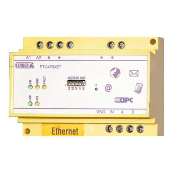
Page 14: Display And Operating Elements
Yellow FAULT LED lights in case of disturbances on the BMS bus, when an FAULT unvalid BMS address has been set and/or in case of FTC470XET malfunctions or when there is no master on the BMS bus. Green LED lights permanently when there is a connection to the next Eth- LINK ernet node (hub, switch, router, PC, etc.). -
Page 15: Address-Dip Switch And Reset Micro Pushbutton
The FTC470XET protocol converter 4.3.2 Address-DIP switch and Reset micro pushbutton The DIP switch is intended for binary BMS bus address assignment: 1-30 (1 = Master mode) The BMS addresses 0 and 31 are not permitted to be set! ADDRESS BMS A4 A3 A2 A1 A0 Dec. -
Page 16: Bms Side Of The Ftc470Xet
If it fails to take over the master function, address 3 will be the next and so on. That means that an FTC470XET with BMS address 2 is more likely to take over the redundant master function than a device with address 30. -
Page 17: Ethernet Side Of The Ftc470Xet
"Basic configuration" on page 19. 4.6 Intended use The FTC470XET protocol converter connects the serial Bender BMS bus to a TCP/IP network via Ethernet. The converter is capable of transmitting data from the BMS bus to the TCP/IP network and vice versa. - Page 18 The FTC470XET protocol converter TGH1375en/02.2010...
-
Page 19: Installation
Prior to installation and connection, an address has to be assigned to the FTC470XET. What you need is: A free BMS address between 2 and 30 for FTC470XET or a permission to assign the master function to the device, that means, BMS address 1 is assigned to the FTC470XET. -
Page 20: Adapting A Single Pc To The Network Parameters Of The Ftc470Xet
For changing the default network parameters of your single PC: (e.g. with Windows 2000) proceed as follows: 1. Connect the PC to the FTC470XET with a cross-over-patch LAN cable. 2. Now open the start page using the path Start/Settings/Network and DFÜ connections. There dou- ble-click ( your) LAN connection. -
Page 21: Setting The Ip Address And Network Mask Of The Ftc470Xet
Confirm with "Send" Now you have access to the parameterisation functions. 4. Click FTC470XET (mostly address 1) in the BMS Explorer in order to view the sub menu items. Then select "Set network parameters", the appropriate window will appear. 5. By way of example, it is assumed that you have received the following network data for the FTC470XET from the person responsible for the installation: IP address: 172.16.10.54... -
Page 22: Resetting The Network Parameters To Factory Setting
Installation server is now only accessible via the new IP address. Close the browser. After approximately 30 seconds, the FTC470XET will be ready for operation again, signalled by a per- manently lit green ON LED. 7. Change the IP address and net mask of your single PC once again in order to be able to address the FTC470XET although it has got a new address. -
Page 23: Mounting And Connection Of The Device
The following description is based on the assumption that the device is connected to a local network (LAN). 1. DIN rail mounting Snap the clamping springs at the rear of the FTC470XET into place in a way that a tight and secure fit is ensured. 2. Connection to supply voltage U Connect the terminals A1 and A2 to a supply voltage of U = 85 to 275 V (AC/DC). -
Page 24: Wiring Diagram
IP Address, Net Mask, Password Fig. 5.1: Wiring diagram for FTC470XET Do not wire the terminals GND and IN permanently with a bridge. A permanently con- nected bridge and the Reset button pressed would automatically reset the network parameters to the factory setting. This may cause serious malfunctions in installations under operating conditions. -
Page 25: The User Interface Of The Internal Web Server
Configuration of the browser In order to be able to query and parameterise the FTC470XET smoothly, it is necessary to enable cookies and to minimise the security restrictions. For that purpose, set the FTC470XET IP address to "Trusted" in the security settings of your browser and allow cookies for this address. - Page 26 For this reason, Web servers with listed addresses are classified as "Trusted" and are called up with low security barriers. When using the Internet Explorer, allow the FTC470XET to use Cookies in the Privacy ru- bric: 1. Start the Internet Explorer and open the "Internet options" window via the path Tools/Internet options.
-
Page 27: User Interface Structure
The user interface of the internal Web server 3. Enter the valid Web address of the FTC470XET into the upper edit field, z.B. http://192.168.0.254 and press "Allow". Confirm with OK. The address will be added to the list below. That allows "Cookies" to be used continuously for Web addresses listed in this field, regard- less of other Cookie restrictions. -
Page 28: The Bms Explorer
The user interface of the internal Web server 6.3 The BMS explorer In the description below, the FTC470XET protocol converter and an RCMS470-12 are con- nected via a BMS bus and form a small bus system. Once a Web browser displays the FTC start page, the BMS explorer becomes visible in the left column. - Page 29 The user interface of the internal Web server Default view BMS administrator view System administrator view Tab. 6.1: Default view of submenus or password-protected administrator view TGH1375en/02.2010...
-
Page 30: Standard Menu, Not Password-Protected
Recording of all channel-related measuring values of the pre- Data logger viously selected BMS devices. Bender URLs By way of example, the URL of the Bender Websites and a vir- (examples) tual e-mail address has been entered (see figure on page 28) Address 1:... -
Page 31: Submenu For The Parameterisation Of Ftc470Xet, Password-Protected
System logger setting The memory for system events can be deleted here. Select the BMS addresses of FTC470XET to be monitored for device failure. The Setting the remaining addresses should be deactivated with "No" so that unassigned device monitoring addresses are blanked automatically during monitoring. -
Page 32: The Monitoring And Parameterisation Frame
The user interface of the internal Web server 6.4 The monitoring and parameterisation frame The contents of this frame is controlled via the BMS explorer depending on the menu item selection. 6.4.1 Calling up the menus and submenus The menus and submenus are called up via the BMS explorer using the mouse. For details refer to "chapter 6.3 The BMS explorer". -
Page 33: Input Devices
The user interface of the internal Web server 6.4.3 Input devices For monitoring or parameter setting, different tools are required. Monitoring For monitoring tasks, the following buttons are required: Parameter setting There are different ways of entering the appropriate values and statuses for parameterisation. For this purpose, the user interface provides: Edit fields for entering texts and values. -
Page 34: Main Menu Functions
The user interface of the internal Web server 6.5 Main menu functions 6.5.1 The start page After addressing the internal Web server using a browser, the start page appears in the frame on the right.This page on the one hand is intended to select a language for the user interface, on the other hand the password allowing the access to protected submenus can be entered here. -
Page 35: History Memory
The user interface of the internal Web server or alarm value, details about the source of alarm are indicated, that means the BMS address, the BMS channel and the measuring point being monitored. The alarm messages are updated automatically every 30 seconds. 6.5.6 History memory After clicking this menu item, a table appears listing up to 600 alarm messages in chronolog-... -
Page 36: Activating Previously Configured Intranet/Internet Or E-Mail Addresses (Optional)
An example for such an application is illustrated on page 47. 6.5.8 Activating previously configured Intranet/Internet or e-mail addresses (option- If required or if it makes sense, up to two of these addresses can be stored in the FTC470XET (page 40). Intranet/Intranet It is possible to access preconfigured Intranet/Internet addresses by using the BMS explorer. -
Page 37: The Functions Of The Ftc470Xet Submenu
Other time zones are not considered. Before changing to other time zones, the summertime changeover function has to be deactivated. 6.6.5 Entering system description This submenu item can be used to change the description of the location of the FTC470XET. It suggests itself that the device description is permanently set. TGH1375en/02.2010... -
Page 38: Data Logger Setting
The user interface of the internal Web server 6.6.6 Data logger setting This submenu can be used to configure up to 20 data loggers. The loggers are assigned ac- cording to the channels and BMS address. The BMS data are recorded depending on the pre- set percentage modification of a measuring value. -
Page 39: Device Monitoring Setting
The user interface of the internal Web server 6.6.9 Device monitoring setting A device on the BMS bus is automatically recognised by the protocol converter via its BMS bus address.You can use the submenu item "Device monitoring setting" to specify which BMS addresses are to be monitored for failure. -
Page 40: Storing Two Addresses In Internet Format (Enter Url For Links)
2. Enter an appropriate short term for the address to be stored into the edit field "Description new Link". 3. Enter an appropriate address (max. 100 characters) into the "URL new" edit field. For example: – for calling up the Web server: http://www.bender-de.com – or for sending an e-mail: mailto:info@bender-de.com – or for calling up a file: file:///c:/service/infos/anschluss.txt... -
Page 41: Network Parameter Setting
At least one IP address and the associated net mask are required to be able to communicate with the protocol converter. The other parameters can optionally be entered according to their configuration. If the FTC470XET is to be connected to the computer network, in any case, the EDP administrator in charge of must be consulted. -
Page 42: E-Mail Parameter Setting For Notification In Case Of Alarm
Enter the IP address of the mail server (SMTP) that is to be used for e-mail forwarding by the protocol converter FTC470XET into the associated edit field. If your pro- vider requires a POP3 authentication before forwarding the e-mail, also enter the IP address of this server into the respective edit field. - Page 43 5. Sender: You can modify the e-mail sender. Up to 50 characters may be entered into the edit field. Please make sure that the sender's e-mail account is registered with ISP. Factory setting = ftc470xet Example: ftc470xet@web.de 6. User (POP3/AUTH LOGIN): Enter the user name predefined by ISP in order to get access to the e-mail server/POP3 server.
-
Page 44: Sending A Test Mail
2. Click on "Password parameter setting". 3. Enter the valid administrator password into the edit field. After correct input it will be confirmed. 4. Click on the menu item "Address X : FTC470XET“ in the BMS explorer. The associated submenu will be opened. -
Page 45: Web Server Application Examples
7. Web server application examples By way of example, a residual current monitoring system and an insulation monitoring de- vice are used to illustrate the parameter setting and monitoring of bus-capable devices. 7.1 Monitoring of an RCMS470-12 connected to the BMS bus The menus and submenus are selected using the BMS ex- plorer. -
Page 46: Calculating Actual Measured Values
Web server application examples Submenu: System description Channel 1 to 12: Function Measuring point, alarm text Text New text 7.1.1 Calculating actual measured values The actual measuring values of a circuit monitored by a CT are to be calculated. The CT itself is monitored by an RCMS470-12 with BMS address 5. -
Page 47: Displaying Collected Data Logger Information In Excel
Web server application examples 7.1.3 Displaying collected data logger information in Excel Transfer the collected data from the data logger into an Excel table sheet and modify the data to display it in a diagram. Extract from the data collection copied to Excel Extract from the modified data collection 06.04.2004 16:21... -
Page 48: Parameter Setting Of An Rcms470-12 Connected To The Bms Bus
Using the BMS administration menu, as illustrated on the left, you can set the parameters of a bus-capable Bender device. At least one administrator password is re- quired for parameter setting. Prior to parameter setting, use the sub menu item "Device information"... -
Page 49: Monitoring An N Conductor For Undercurrent
Web server application examples 7.2.2 Monitoring an N conductor for undercurrent An neutral conductor can be monitored for interruption using the "undercurrent monitoring" function. Perform the steps as described in the preceding example above and select "Under- current monitoring". Submenu: Set function - Overcurrent/residual current monitoring Channel 1 to 12: Function... -
Page 50: Setting A Ct Correction Factor
Web server application examples 7.2.4 Setting a CT correction factor At channel 2 of an RCMS470-12 with address 5, the CT has to be replaced. The nominal cur- rent of the new CT is equal to the old one but its secondary output is 50% lower than that of the old one. -
Page 51: Discriminator Circuit With Rcms470-12 (Monitoring A "Window")
Web server application examples 7.2.5 Discriminator circuit with RCMS470-12 (Monitoring a "window") The operating current on a conductor may fluctuate between 11 mA and 30 mA. When the value is outside the permissible range, an alarm is to be signalled. The conductor is moni- tored by one CT, the input channels 2 and 4 of the residual current monitor are connected in parallel and therefore receive the same CT signal. -
Page 52: Changing An Alarm Text Or A Measuring Point Description
Web server application examples 7.2.6 Changing an alarm text or a measuring point description In some cases it may be useful to adapt an alarm text to the special local requirements. For example, if there is the requirement that an RCMS470-12 with BMS address 5 should display the message "Undercurrent"... -
Page 53: Monitoring An Irdh275B Connected To The Bms Bus
Web server application examples 7.3 Monitoring an IRDH275B connected to the BMS bus The menus and submenus are selected using the BMS Ex- plorer. The standard menus, as illustrated opposite, pro- vide an overview about the configuration and the current measuring values of a system consisting of bus-capable de- vices. -
Page 54: Parameter Setting For An Irdh275B Connected To The Bms Bus
An example of device setting is shown in the illustration below. Prior to parameter setting, make sure that you have entered an administrator password. You cannot access the required submenu items without having administrator rights. Go to the "Start page" of the FTC470XET to enter the password. TGH1375en/02.2010... -
Page 55: Setting The Parameters For Response Values, Operating Principle Of The Relays And Starting Time Of The Automatic Self Test
Web server application examples 7.4.1 Setting the parameters for response values, operating principle of the relays and starting time of the automatic self test Higher response values R and R are to be assigned to an IRDH275B so that in case of higher insulation values Alarm 1 and 2 will be triggered: =100 kΩ... - Page 56 Web server application examples TGH1375en/02.2010...
-
Page 57: Application Of The Internal Opc Server
8. Application of the internal OPC server 8.1 Function The FTC470XET contains a network-capable OPC server continuously providing the alarm and operating messages of the BMS bus being monitored. For retrieving this OPC data, an appropriate client is to be used. The data is provided by the OPC server as items. Parallel access of several clients is possible. -
Page 58: Opc Compatibility With Windows 2000 Or Windows Xp
Application of the internal OPC server 8.2 OPC compatibility with Windows 2000 or Windows XP The OPC software interface is based on Microsoft DCOM technology. By default, the DCOM interface of a Windows operating system is protected. If a connection between a Windows- based PC and an OPC server cannot be established, some restrictions of the DCOM interface have to be removed. - Page 59 Application of the internal OPC server Windows 2000 3. In the "Default Properties" menu, select "(None)" from the "Default Authentication Level" field. Select "ANONYMOUS" from the "Default Impersonation Level" field. Confirm with "Apply". Windows XP 3 In the "Default Properties" menu, select "(None)" from the"Default Authentication Level" field. Select "ANONYMOUS"...
- Page 60 Application of the internal OPC server Windows 2000 5. The "Registry value permissions" window will open. Click "Add". The window "Select Users, Computers, or Groups" will appear. Select the user group "Everyone" and confirm with "Add". The selected user group will appear in the field at the bottom of the list.
- Page 61 Application of the internal OPC server Fig. 8.5: -- -- Windows XP Windows 2000 6. Now click the menu item "Default launch permissions" and click "Edit Default". The window "Registry Value Permissions“ will appear. Click "Add". The window "Select Users, Computers, or Groups" will appear. Select the user group "Everyone"...
- Page 62 Application of the internal OPC server Summary: The following modifications have been made due to the DCOM settings described in this chapter. If you want to reset some DCOM settings, consider the values listed under "Settings OLD" or remove all user groups (Everyone) that have been added. Windows 2000 Menu Menu item...
-
Page 63: Displaying Bms Data Using The Opc Demo Client
3. Type the IP address of the FTC470XET into the edit field. The OPC server is also accessible under this IP address. Click the plus sign next to the address icon, the address will be applied and the next level will be displayed. -
Page 64: Data Collection Of The Whole Bms System Via Bms Addresses And Channels
8.3.2 Data collection of the whole BMS system via BMS addresses and channels 1. Double-click the server icon or click the "Bender OPC Server" writing (under Data Access V2). A basic structure will appear in the frame on the left. -
Page 65: Compilation Of The Bms Addresses Being Monitored, Bms Channels And Items
Application of the internal OPC server 8.3.3 Compilation of the BMS addresses being monitored, BMS channels and items A precondition is that the view "DA Browse" has been set. 1. Double-click all items of the BMS channels 2 and 4 in the right frame. The selected value, type and alarm items under their predefined group name will appear in the left frame. -
Page 66: Monitoring Of The Compiled Bms Addresses, Bms Channels And Items
Application of the internal OPC server 8.3.4 Monitoring of the compiled BMS addresses, BMS channels and items 1. Select "DA Items" using the respective tab. 2. The numerical values referring to the items already selected will be displayed in the column "Value". Interpretation: Value-Item = 30 ==>... -
Page 67: Channels, Data Types And Data Values Of Bms Devices
Application of the internal OPC server 8.4 Channels, data types and data values of BMS devices 8.4.1 Alarm messages Alarm messages develop when the response value of a device is exceeded or has fallen below a response value. Depending on the type of device these may be measuring values or statuses of a device. - Page 68 Application of the internal OPC server BMS data Function Device channel data type value MK2418-11 Control fault SMI470-9 Failure switching element K1 or Q1 PRC487 Failure switching element K2 or Q2 PRC487 107TD47 Fault insulation monitoring device IRDH... IZ427 Changeover module in manual mode PRC487 Open circuit closing coil K1 PRC487...
- Page 69 Application of the internal OPC server BMS data Function Device channel data type value Residual current/overcurrent/undercurrent fault in A RCMS... 1...12 value Residual current/overcurrent/undercurrent fault RCMS... 1...12 value > [value] in A Prewarning residual current fault in mA RCMS... 1...12 value Prewarning residual current fault in A RCMS...
-
Page 70: Operating Messages
Application of the internal OPC server 8.4.2 Operating messages Operating messages are information and/or measured values continuously provided by BMS devices and queried by the BMS master via the bus. Some BMS devices (EDS47x) do not pro- vide operating messages, but only alarm messages. BMS data Function Device... -
Page 71: How To Use The Ftp Server
(to transfer the files to the clipboard). Return to the file window of the FTC470XET and press "Strg“ and "V" in order to insert all files (overwrite mode). - Page 72 Note! The FTP addresses displayed are without function when the browser gets access to the FTC470XET via the Internet and is using the Internet connection NAT (Network Address Translation). In this case, contact your administrator.
-
Page 73: Service And Support
Ethernet cable (RJ45) is correctly connected; the BMS address is correctly set; the start page of the FTC470XET Web server can be accessed by a Web browser;. the network parameters are correctly set, at least the IP address and the net mask. -
Page 74: Warranty And Liability
Any guarantee obligation will be rendered null and void if repairs or changes have been made to equipment by persons other than those authorised to do so by BENDER. BENDER does not accept any liability for direct or indirect collateral or consequential dam- age regardless of whether this can be attributed to action considered permissible, impermis- sible or otherwise. -
Page 75: Technical Data
Device address / factory setting....................per DIP switch, 1...30 / 1 OPC via Ethernet: OPC data access ................................v 2.0 ProgID .......................... Bender.OPC.Server.FTC470XET.DA System configuration of the FTC Web server, of the BMS devices connected to the FTC: Password, factory setting..............................ftc General data EMC immunity ............................. -
Page 76: Dimension Diagram
Flammability class ............................... UL94 V-1 Software-Version ............................D176 V1.11 ....................................D177 V2.2x Weigth ................................approx. 350 g 11.2 Dimension diagram The FTC470XET is incorporated in an enclosure of the 470 series, as illustrated below. 99 mm ø 4,3 mm 91 mm ø 4,3 mm Possible is: DIN rail mounting acc. -
Page 77: Ordering Information
Technical data 11.3 Ordering information Supply voltage U Type Art. No. FTC470XET AC 85...276 V / B 9506 1001 (X470 enclosure, see dimension diagram) DC 85...276 V FTC3000XET (in aluminium case, 270 x 205 x 115 mm, AC 85...276 V... - Page 78 Technical data TGH1375en/02.2010...
-
Page 79: Frequently Asked Questions
What should be done? Answer: Probably there is a communication problem. It is recommended to repeat the request. The FTC470XET does not provide answers to the requests. The "ON" LED at the device lights up per- manently. What should be done? Answer: The device does not operate properly, a hardware reset has to be carried out. - Page 80 Frequently asked questions: TGH1375en/02.2010...
-
Page 81: Index
Frequently asked questions the OPC server damage in transit FTC470XET features - Monitoring of the compiled Data logger FTC470XET is not accessible BMS devices Data logger setting FTP server - Starting the client DCOM interface OPC compatibility with the opera-... - Page 82 Password protection POP3 authentication before SMTP authentication Warranty Warranty claims quick reference guide Web browser Wiring diagram FTC470XET Work activities on electrical instal- lations RCMS470-12 monitoring Redundant master function RESET pushbutton R Reset to default view Resetting the IP address...
- Page 84 Dipl.-Ing. W. Bender GmbH & Co. KG Londorfer Str. 65 • 35305 Grünberg • Germany Postfach 1161 • 35301 Grünberg • Germany Tel.: +49 6401 807-0 Fax: +49 6401 807-259 E-Mail: info@bender-de.com Web server: http://www.bender-de.com...
Need help?
Do you have a question about the FTC470XET and is the answer not in the manual?
Questions and answers