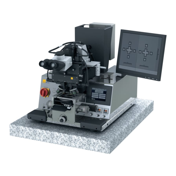
SUSS MJB4 User Manual
Laboratory mask aligner
Hide thumbs
Also See for MJB4:
- User manual (164 pages) ,
- Safety and installation (52 pages) ,
- Manual (8 pages)
Table of Contents
Advertisement
Advertisement
Table of Contents

Related Manuals for SUSS MJB4


Summary of Contents for SUSS MJB4
- Page 1 USER MANUAL Mask Aligner MJB4 Laboratory Mask Aligner Rev07/ 05-10 www.suss.com...
- Page 3 SUSS MicroTec assumes no responsibility for any errors, omissions, or inaccuracies. The information included in this manual is SUSS MicroTec Proprietary Information and is provided for the use of SUSS MicroTec’s customers only and cannot be used for distribution, reproduction, or sale without the express written permission of SUSS MicroTec.
- Page 4 DISCLAIMER AND PUBLISHING DETAILS DISCLAIMER...
-
Page 5: Table Of Contents
1.5.3. Electrical Dangers .................2 1.5.4. Radiation Danger ..................3 1.5.5. Danger of Poisoning ................3 1.6. Working with the MJB4 Mask Aligner .............3 1.6.1. Fitting, Changing and Cooling the Exposure Lamp .......4 1.6.2. Preparing the Machine for Working ............5 1.6.3. Safety Checks ..................6 2. - Page 6 3.8. Step-by-Step Machine Operation ..............36 3.8.1. Selecting exposure program, e.g., soft contact ........36 3.8.2. Programs .....................37 3.8.3. Loading, Aligning and Exposing the Substrate ........38 4. SPECIALS ......................39 4.1. Nano Imprint Lithography - NIL ..............39 ORIGINAL DOCUMENTATION MJB4 - Contents Rev07 05-10...
- Page 7 CONTENTS 5. MAINTENANCE ....................47 5.1. Parameter Ranges and Default Settings ............47 5.2. Service Information ..................48 5.2.1. Overview .....................49 5.3. Lock-Out / Tag-Out Checklist ................54 ORIGINAL DOCUMENTATION MJB4 - Contents Rev07 05-10...
- Page 8 CONTENTS ORIGINAL DOCUMENTATION MJB4 - Contents Rev07 05-10...
-
Page 9: Preface
PREFACE PREFACE The MJB4 Mask Aligner is a precision instrument for Different versions of the aligner are available. high-resolution photolithography and is intended for use in research laboratories, small-series production A single field microscope and a splitfield and pilot projects. - Page 10 PREFACE MJB4 - Preface Rev06 10-09...
-
Page 11: Warnings And Safety Precautions
Any other form of use must be agreed on with SUSS MicroTec Lithography's Engineering Product Sup- Attention! port department. -
Page 12: Dangers
High wattages and currents of up to 50 A can occur Stop looking into the microscope view- in the lamp and lamp power supply. finder before you start the microscope The lamp starting voltage can be up to 30 kV. movement! MJB4 - Warnings and Safety Rev07 05-10... -
Page 13: Radiation Danger
• Follow the general and national safety regula- tions relating to Hg! • A doctor should be consulted immediately if there is a possibility of mercury fumes having been in- haled! MJB4 - Warnings and Safety Rev07 05-10... -
Page 14: Fitting, Changing And Cooling The Exposure Lamp
Hg-filled UV high-pressure lamps must be changed P.O. Box 100121 once the service life specified by the manufacturer D-76231 Karlsruhe has expired. There is an increased risk of lamp ex- http://www.carl-roth.de plosion after this date! MJB4 - Warnings and Safety Rev07 05-10... - Page 15 1.6.1.2. Changing the Lamp diation of heat) in the lamp house. The lamp-specific values both for the adjustment of Only use lamps of a type approved for use by SUSS the blowing of nitrogen onto the upper and lower MicroTec Lithography! lamp caps and also for the extraction should be ob- served.
-
Page 16: Preparing The Machine For Working
The important safety functions of the machine should be checked for safe functioning at regular in- tervals - i.e at least every three months. This applies as long as the check itself does not rep- resent a hazard. MJB4 - Warnings and Safety Rev07 05-10... -
Page 17: Installation And Transport
(4 in) away from the room wall. See the figure “Di- • The room temperature and relative humidity mensions of the MJB4 Mask Aligner:” for the ex- should be controlled at the setup site. act dimensions of the aligner. --> We recommend a room temperature -->... - Page 18 Nitrogen [l/h] Must be set by Shutter service technician Diameter of exhaust [mm] closed closed closed needs adapter tube on bottom required outlet temp.< 60°C Notes reduced for DUV appl. DUV+Ozone REVERSED polarity! MJB4 - Installation and Transport Rev07 05-10...
- Page 19 1 Nitrogen 6 F3 - External Power 2 CDA 7 Main Power 3 Vacuum 8 External Power 4 Outgoing air 9 Lamp Power Supply 5 F2 - Lamp Power Supply 10 External Power MJB4 - Installation and Transport Rev07 05-10...
-
Page 20: Transporting The Mask Aligner
Users who transport the machine without a SUSS tainers MicroTec service technician or a person authorized by SUSS MicroTec do so at their own risk. • If shipping damage is suspected, do not open containers until a SUSS MicroTec service 2.2.1. - Page 21 We recommend using cross beam part no.: 187724 for transporting the machine (see figure: Warning! “Transporting the MJB4 using a cross beam”). The center of gravity is behind the mid- The cross beam ensures that the transport straps dle of the machine (lamp housing).
-
Page 22: Transportation Locks
Alignment Stage TSA Microscope Manipulator 1 Screw 1 (2x) 1 Screw 1 2 Screw 2 (3x) 2 Screw 2 3 Screw 3 (2x) 4 Plastic plate 5 Transport lock (marked red) MJB4 - Installation and Transport Rev07 05-10... -
Page 23: Taking The Machine Out Of Service
INSTALLATION AND TRANSPORT 2.2.6. Taking the Machine out of Service Before shutting down the machine for a longer period of time, you must be advised by a SUSS MicroTec service technician. We strongly recommend the following before long- term decommissioning: •... - Page 24 INSTALLATION AND TRANSPORT MJB4 - Installation and Transport Rev07 05-10...
-
Page 25: Operation Of The Mjb4
3. OPERATION OF THE MJB4 The MJB4 Mask Aligner allows contact exposures of The MJB4 is equipped with 400 nm exposure optics different types (vacuum, hard, soft contact) as well and lamps that allow a resolution of< 1µm in vacuum as exposures at short distances and can be used to contact. -
Page 26: Definitions
The travel path is ±5 mm. Stage - Y Motion This micrometer screw is located on the left side of the alignment stage and moves the substrate in Y- direction. The travel path is ±5 mm. MJB4 - Operation Rev07 05-10... -
Page 27: Display/Touch Screen
3.4.7. "Setting the Mask Substrate Thick- 3 Screen name ness". 4 Screen number 5 Menu selection Note: After 30 minutes without action the monitor is switched off (screen saver). Touching the panel switches it on again. MJB4 - Operation Rev07 05-10... -
Page 28: Topside (Tsa) Microscope Manipulator
TSA Microscope Manipulator coarse focusing. TSA Theta Motion 1 Movement in the Y direction 2 Movement in the X direction The small knob on the front upper right side rotates the microscope around the Z-axis. MJB4 - Operation Rev07 05-10... -
Page 29: Microscope Illumination
TSA/IR Microscope Illumination Depending on which illumination type is selected, the TSA or IR illumination can be set using the left/ right ILLUMINATION potentiometers on the left front plate. MJB4 - Operation Rev07 05-10... -
Page 30: Lamp House
The lamp must be on for about 20 minutes before it reaches operating temperature. The Lamp test function can be selected in the main menu. Using the SUSS UV1000 intensity meter with the Basic pneumatic settings appropriate probe, you check and set the intensity and uniformity of the light. - Page 31 The nitrogen is injected from the back of the mask holder frame between the mask and substrate. The volume of nitrogen can be set using the PURGE MASK HOLDER throttle. MJB4 - Operation Rev07 05-10...
-
Page 32: Main Screens And Menu Navigation
Depending on the selected exposure program different parameters can be pro- grammed. • The button Recipes gives access to the recipe editor. Here new recipes can be stored or exist- ing recipes can be selected and deleted. MJB4 - Operation Rev07 05-10... - Page 33 The desired values can be typed in and are con- firmed with ENTER. • Pushing the arrow key Load activates the se- lected program. MJB4 - Operation Rev07 05-10...
- Page 34 The button Exposure starts the program se- quence and performs exposure without a stop. • When pressing the button Parameters the pro- gram jumps back to the parameter screen and the actual data can be changed. MJB4 - Operation Rev07 05-10...
-
Page 35: Operating Sequences
MJB4 OPERATION OF THE 3.4. Operating Sequences and the MJB4 electronics switches off automatically after the cool down phase is complete (10 minutes). 3.4.1. Switching the Machine On/ IMPORTANT NOTE: • To switch on the mask aligner, select the start page and press the Electronics ON/OFF but- 3.4.1.1. -
Page 36: Switching On And Calibrating The Exposure Lamp
EMO at the mask Exposure Cycles aligner and inform the service department of SUSS MicroTec. If more than one exposure cycle is entered, the pause time between the individual cycles can be SUSS MicroTec assumes no liability for damages changed. -
Page 37: Saving And Loading Programs
Main menu. The recipe name is shown on top of the display. Attention! If you press the CLEAR button, all se- lected parameters are deleted and the program space is available again. Alphanumerical keyboard MJB4 - Operation Rev07 05-10... -
Page 38: Loading The Mask
At the touch screen appears: „Close contact lever“ Move the substrate towards the mask by pushing the contact lever forwards. Afterwards turn the thickness setting upwards (counterclockwise) until the information „WEC setting OK“ appears on the display. MJB4 - Operation Rev07 05-10... -
Page 39: Wedge Error Compensation Pressure
Doing so No alignment must be done if the mask will damage the mask and substrate. and substrate are in contact. The display shows the page: „Align substrate...“ Doing so may damage the mask and substrate! MJB4 - Operation Rev07 05-10... -
Page 40: Adjusting The Microscope
To do this, use the OBJECTIVE FOCUS FINE MANUAL knob on the microscope. Set the TSA Microscope to the Mask Alignment Crosses. The right/left microscope is set to the right/left mask alignment crosses with OBJECTIVE X- SEPARATION. MJB4 - Operation Rev07 05-10... -
Page 41: Exposure
See section 3.4.6. "Loading the Substrate". mask holder and place it on a tray upside down. Caution! Switch off the mask vacuum by pressing the Mask vacuum is on button. The microscope pivots downward! The mask can now be removed. MJB4 - Operation Rev07 05-10... - Page 42 Switch off the mask vacuum by pressing the Mask vacuum is on button. 3.6.1.5. Aligning the Substrate The mask can now be removed. Focusing the Substrate Level For fine lens adjustment, use the OBJECTIVE FOCUS FINE MANUAL knob on the microscope. MJB4 - Operation Rev07 05-10...
-
Page 43: Transmitted Light
The Parameters menu must be selected on the Checking the Alignment touch screen and the illumination must be set to Infrared transm.light. The IR illumination arms can See section 3.5.5. "Aligning the Substrate". now set precisely under the lenses. MJB4 - Operation Rev07 05-10... -
Page 44: Exposure Programs
It also prevents gas bubbles from forming under the substrate. In the next stage the final vacuum is applied. The intake vacuum is then replaced with nitrogen overpressure. This results in the best possible contact between the MJB4 - Operation Rev07 05-10... -
Page 45: Low Vacuum Contact Exposure
• Up to 99 cycles are programmable. • After each cycle a new exposure time must be entered to perform the next test exposure step. MJB4 - Operation Rev07 05-10... -
Page 46: Step-By-Step Machine Operation
50 µm EXPOSURE TIME selection EXPOSURE TIME Enter the exposure time in the sub- menu and press ENTER to confirm Confirm the set parameters with Load MAIN MENU MJB4 - Operation Rev07 05-10... -
Page 47: Programs
Menu in the Display Button Strokes in the Display MAIN MENU RECIPES RECIPE EDITOR SELECT Select existing program space RECIPE EDITOR LOAD The display switches back to the main menu The machine is ready for use MAIN MENU MJB4 - Operation Rev07 05-10... -
Page 48: Loading, Aligning And Exposing The Substrate
EXPOSURE For exposing the substrate WARNING! Microscope pivots upwards Mirror housing and microscope move towards the operator. UNLOAD SUBSTRATE Pull the contact lever back, pull out the transport slide and load the substrate MAIN MENU MJB4 - Operation Rev07 05-10... -
Page 49: Specials
4. SPECIALS 4.1. Nano Imprint Lithography - NIL The imprint process is a special application for the sequence which is described below: MJB4 and therefore needs a modified operation Screen Page: Start • The start screen appears after switch-ON and initialisation of the machine •... - Page 50 • Confirm with Load Screen Page: Main menu Imprint • The program displays the Main menu Imprint Screen. • Press Start Process • The program prompts the operator to load the stamp on the stamp holder. Specials MJB4 Rev06 10-09...
- Page 51 (clockwise) to be within a save distance for WEC. • The program prompts the operator to load the substrate without resist. • The subsequent steps are • • WEC pressure adjustment Specials MJB4 Rev06 10-09...
- Page 52 (down) to move the sub- strate into a save distance. This is necessary to avoid contact of the coated substrate with the stamp before starting the im- print process. • Press next to continue. Specials MJB4 Rev06 10-09...
- Page 53 • Close the contact lever. The substrate is moved into alignment position. • Now the substrate can be aligned to the stamp. • As soon as you are finished press next to con- tinue. Specials MJB4 Rev06 10-09...
- Page 54 „POSITION REACHED !“ starts flashing. The screen displays the options • N2 under wafer on/off • Wafer Vacuum on/off • Depending on your selection the options toggle between ON and OFF. • Press next to continue. Specials MJB4 Rev06 10-09...
- Page 55 The screen shows the message Open the contact lever Unload substrate + template • Turn the contact lever to move the substrate package down • Pull out the transport slide with the chuck and the substrate package and unload. Specials MJB4 Rev06 10-09...
- Page 56 SPECIALS Specials MJB4 Rev06 10-09...
- Page 57 5 sec. [0.1…999.9] wafer before exposure Pre Vac Length of pre-vacuum 5 sec. [0.1…999.9] Full Vac Length of main vacuum 5 sec. [0.1…999.9] Vac Purge purge time of mini 5 sec. [01…999.9] chamber following vacuum exposure Maintenance MJB4 Rev06 10-09...
- Page 58 Shutter, closer 11/V2 Shutter, opener 11/V3 Lamp house, focus cooling 11/V4 Lamp cooling (shutter and upper and lower lamp socket) 12/V1 Microscope lift up/down 12/V2 TSA manipulator brake, X- and Y-direction 15/V1 Mirror house forward/ back Maintenance MJB4 Rev06 10-09...
- Page 59 5.1.1.3. Pneumatic Controllers (PG) Identifier Medium Function 0PG1 - B5 Machine main air pressure 0PG2 - B6 Machine main nitrogen pressure 0PG3 - B7 Vacuum 1/FM1 - B10 Flowmeter 5/PG1 - B8 WEC pressure 8/PG7 - B9 Vacuum chamber Maintenance MJB4 Rev06 10-09...
- Page 60 Z axis Contact position Z axis align position Z axis Z-grab position Microscope up / down Mirror house front Mirror house back WEC head brake Main switch - ON Lamp cooling Air pressure limit Nitrogen limit Vacuum limit Maintenance MJB4 Rev06 10-09...
- Page 61 MAINTENANCE 5.2. Lock-Out / Tag-Out Checklist Maintenance MJB4 Rev06 10-09...
- Page 62 MAINTENANCE Maintenance MJB4 Rev06 10-09...
- Page 64 Phone (+49)-(0) 89/3 20 07-0 200041 Shanghai PRC Fax (+49)-(0) 89/3 20 07-162 Phone (+86) 21-52340432 Fax (+86) 21-52340430 SUSS MicroTec (Taiwan) Co., Ltd. NORTH AMERICA 8F-11, No. 81, Shui-Lee Road Hsin-Chu l 300 l Taiwan Phone (+886)-(3)-5169098 SUSS MicroTec Inc.
Need help?
Do you have a question about the MJB4 and is the answer not in the manual?
Questions and answers