Table of Contents
Advertisement
Quick Links
Advertisement
Table of Contents

Related Manuals for SUSS MA6


Summary of Contents for SUSS MA6
- Page 1 USER MANUAL Mask Aligners MA6 / MA8 Manual Mask Aligner Rev05/ 07-06 www.suss.com...
-
Page 3: Table Of Contents
Changing the TSA, BSA and Stage Alignment Speed .......... 32 1.5.5 EDIT PROGRAM Menu ..................33 1.5.6 Change Mask ...................... 34 1.5.7 Load Wafer ......................35 1.5.8 Load Mask by Slide ..................... 36 Maintenance ....................39 General ..........................39 MA6 / MA8 - Contents - Rev.05 07-06... - Page 4 Spare Parts Llist (Extract) ....................57 Lock-Out / Tag-Out Checklist ..................63 Schematics of the Pneumatic System ................65 3.6. Schematics of the Electronic System MA6/8 BA6/8............82 Service Information ......................84 3.7.1 Subassemblies: MA8; MA6; MA6/BA6; BA6; MA6/BA6-ISA; ....... 84 3.7.2...
-
Page 5: Preface
(a detailed description is provided in BA6 Bond Aligner manual) All of the tooling for the MA6 and MA8, e.g. chucks, mask holders and mask holder adapter frames can be used on both mask aligners. Excepted from this are the BSA chucks for BSA microscopes with split-field magnification. - Page 6 MA6 / MA8 - Preface - Rev.05 07-06...
- Page 7 Attention ! Attention ! It is strongly recommended to read this User Manual before starting the Mask Aligner the first time. MA6 / MA8 - Attention ! - Rev.05 07-06...
- Page 8 MA6 / MA8 - Attention ! - Rev.05 07-06...
-
Page 9: Operation Of The Machine
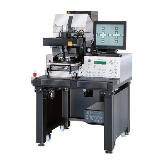
3 Upper panel control SUSS Mask Aligner MA6 4 Alignment stage 1 EMERGENCY POWER OFF 5 Keyboard 2 TSA microscope MA6 / MA8 - 1. Operation of the Machine - Rev.05 07-06... - Page 10 PERATION OF THE ACHINE SUSS Mask Aligner MA8 1 EMERGENCY POWER OFF 2 TSA microscope 3 Front panel 4 Alignment stage 5 Keyboard MA6 / MA8 - 1. Operation of the Machine - Rev.05 07-06...
-
Page 11: Definitions
– LED on: key selected or function active – LED off: key not selected or function deactivated – LED flashing: most applicable key to continue MA6 / MA8 - 1. Operation of the Machine - Rev.05 07-06... -
Page 12: Coordinate Systems
101 MAIN POWER switch 102 EMERGENCY POWER OFF key 103 Knob STG-X-MOVEMENT 104 Knob STG-Y-MOVEMENT 105 Knob STG-Θ-MOVEMENT 1 Mask holder 2 Transport slide 3 Snap in connector mask vacuum MA6 / MA8 - 1. Operation of the Machine - Rev.05 07-06... -
Page 13: Components Of The Exposure Optics
UV protecting goggles and skin protec- available. tion. Also orientation of lenses and the cold light mirror must not be changed. MA6 / MA8 - 1. Operation of the Machine - Rev.05 07-06... -
Page 14: Exposure Lamp
The fly’s eye lens is made of optical UV300 requires quartz glass. grade fused silica for all optical systems. Alternatively for more intensity but with less unifor- MA6 / MA8 - 1. Operation of the Machine - Rev.05 07-06... -
Page 15: Cleaning Of Optical Parts
Extended work in front of a laboratory mask aligner at UV250 or UV300 optics can result in exceeding the MA6 / MA8 - 1. Operation of the Machine - Rev.05 07-06... -
Page 16: Controls And Indicators
Maximal travel ±5mm. 105 Knob STG-Θ-MOVEMENT This is the small knob at the right side of the align- ment stage. Maximal travel ±5°. MA6 / MA8 - 1. Operation of the Machine - Rev.05 07-06... -
Page 17: Front Panel Controls
207 WEC - PRESSURE gauge (with regulator) 322 BSA MICROSCOPE key 208 LCD-display 323 LEFT key 209 CONTACT indicator 324 BOTH key 325 RIGHT key 326 TOP/BOTTOM key MA6 / MA8 - 1. Operation of the Machine - Rev.05 07-06... - Page 18 The two potentiometers in- dividually control the fine focus of the BSA and TSA microscope objectives at the lower focus plane. MA6 / MA8 - 1. Operation of the Machine - Rev.05 07-06...
-
Page 19: Keyboard Controls
324 BOTH key 311 EDIT PARAMETER key 325 RIGHT key 312 EDIT PROGRAM key 326 TOP/BOTTOM key 313 ENTER key 327 GRAB IMAGE key 314 SET REFERENCE key MA6 / MA8 - 1. Operation of the Machine - Rev.05 07-06... - Page 20 If mask and wafer are in contact alignment gap keeping this center position. Cen- (CONTACT INDICATOR on), tering stage off means, the alignment stage move don't align the wafer! MA6 / MA8 - 1. Operation of the Machine - Rev.05 07-06...
- Page 21 EDIT PROGRAM key and toggle to "de- the boot procedure. lete". Select a program number to delete. Delete Press the LOAD key to start the wafer loading proce- the displayed program. dure. MA6 / MA8 - 1. Operation of the Machine - Rev.05 07-06...
- Page 22 Enabled only in the bond-aligner-mode: this clamps the wafers together with or without spacers. 321 OPTION key The X-ARROW keys controls the Θ-movement for the motorized alignment stage when OPTION key is acti- vated. MA6 / MA8 - 1. Operation of the Machine - Rev.05 07-06...
-
Page 23: Tsa-Microscope Controls
402 TSA Z-MOVEMENT knob 403 TSA Θ-MOVEMENT knob 404 OBJECTIVE FOCUS FINE MANUAL knob 405 OBJECTIVE X-SEPARATION knobs 406 CLAMPING SCREW 407 APERTURE TSA-Illumination 408 TSA SPLITFIELD switch 409 Turret MA6 / MA8 - 1. Operation of the Machine - Rev.05 07-06... -
Page 24: M 3Xx Microscope
TSA-objective separately. 408 TSA SPLITFIELD switch Located on the microscope front this switch selects the left, right or both TSA-objective as source for the eyepieces and monitor image. MA6 / MA8 - 1. Operation of the Machine - Rev.05 07-06... - Page 25 Operation of the Machine Dual Video Microscope DVM 6 402 TSA Z-MOVEMENT Knob 403 TSA Θ-MOVEMENT knob 405 OBJECTIVE X-SEPARATION knobs 407 APERTURE TSA-Illumination 409 Turret MA6 / MA8 - 1. Operation of the Machine - Rev.05 07-06...
-
Page 26: Dual Video Microscope Dvm 6/8
For the lamphouse LH 1000 find the adjustment wheel on the upper front side of the lamphouse. Lamp exchanging is possible opening the two knurled screws. MA6 / MA8 - 1. Operation of the Machine - Rev.05 07-06... -
Page 27: Joystick And Buttons
603 SINGLE STEP button Every joystick flexure or arrow key depression will only result in a single step movement in accordance with the value programmed via the F1 key. MA6 / MA8 - 1. Operation of the Machine - Rev.05 07-06... -
Page 28: Operating Procedures
Save the settings by the EDIT "Watch out machine is starting!" PROGRAM key (312). Existing programs can be Now you are asked for: loaded from here. "Select machine configuration: MA6" MA6 / MA8 - 1. Operation of the Machine - Rev.05 07-06... -
Page 29: Top Side Alignment
Hit ENTER to switch the mask vacuum off. Retract the mechanical clamping and remove the mask. MA6 / MA8 - 1. Operation of the Machine - Rev.05 07-06... - Page 30 – pull out transport slide and load wafer: LOAD key The machine instructs: "pull slide and load sub- strate onto chuck". Pull out the transport slide completely. Insert the proper chuck and place the MA6 / MA8 - 1. Operation of the Machine - Rev.05 07-06...
-
Page 31: Bottom Side Alignment
WEC- type proximity. Starting from the initial state of the machine these steps have to be performed: MA6 / MA8 - 1. Operation of the Machine - Rev.05 07-06... -
Page 32: Single Bottom Side Alignment
– select maskloading type: F1 key Make secure that no mask is loaded before select mask loading type. Select mask loading by slide with BSA alignment. MA6 / MA8 - 1. Operation of the Machine - Rev.05 07-06... - Page 33 SCAN activating the TOP/BOTTOM key (326) and the key (315). Press GRAB IMAGE key (327) to store corresponding TOP SUBSTRATE LEFT/RIGHT the reference alignment mark image. Toggle to MA6 / MA8 - 1. Operation of the Machine - Rev.05 07-06...
-
Page 34: Advanced Technology
The vacuum securing the wafer on the chuck is replaced by nitrogen. In this mode the best contact between mask and wafer is achieved. After the expo- sure nitrogen will purge into the mini chamber to MA6 / MA8 - 1. Operation of the Machine - Rev.05 07-06... -
Page 35: Multiple Exposure
Transport slide moves geneous quality of the exposed structures over the down. whole wafer. Set the WEC type using the EDIT PA- RAMETER key (311). MA6 / MA8 - 1. Operation of the Machine - Rev.05 07-06... - Page 36 Align mask now and confirm finally with ENTER key. Mask moves up. Same procedure as described in with- out alignment follows. MA6 / MA8 - 1. Operation of the Machine - Rev.05 07-06...
-
Page 37: Step By Step Machine Interactions
Display message Following operator action (keystroke) "ready for Load" "microscope up/down" "change align speed" "single step config" "centering stage" "select maskloading" ENTER "manual" "slide" "manual" ENTER "ready for load" MA6 / MA8 - 1. Operation of the Machine - Rev.05 07-06... -
Page 38: Select Program For Exposure
"Exposure Type: Soft" "Exposure Type: Flood E" "Exposure Type: Prox" "Exposure Type: Vac" "Exposure Type: Low Vac" "Exposure Type: Hard" "Exposure Type: Soft" SELECT PROGRAM "ready for Load" MA6 / MA8 - 1. Operation of the Machine - Rev.05 07-06... -
Page 39: Edit Parameter Menu
(Edit value by Y and Y ) "Exposure Type: Soft" (Edit value by Y and Y ) Press EDIT PARAMETER key to confirm the edited value "ready for Load" MA6 / MA8 - 1. Operation of the Machine - Rev.05 07-06... -
Page 40: Changing The Tsa, Bsa And Stage Alignment Speed
(Edit value by Y and Y ) "BSA Parameter Slow Speed [%]: 39" ENTER "ready for Load" (to edit the fast speed activate the FAST key, LED on) MA6 / MA8 - 1. Operation of the Machine - Rev.05 07-06... -
Page 41: Edit Program Menu
"EXIT Pgm. Editor" "DELETE Pgm. no: 0" (Edit value by Y and Y ) (Edit value by Y and Y ) "SAVE Pgm to: 0" EDIT PROGRAM "ready for Load" MA6 / MA8 - 1. Operation of the Machine - Rev.05 07-06... -
Page 42: Change Mask
• flip mask holder 180° and slide it back into the machine (up to the end and preverably to the right position) • press CHANGE MASK "ready for Load" MA6 / MA8 - 1. Operation of the Machine - Rev.05 07-06... -
Page 43: Load Wafer
"Microscope moving - please wait..." (exposure takes place) "please wait..." (wafer moves down) "Microscope moving - please wait..." "pull slide and unload exposed substrate" do it "ready for Load" MA6 / MA8 - 1. Operation of the Machine - Rev.05 07-06... -
Page 44: Load Mask By Slide
"no align" "TSA align" "BSA align" ENTER "ready for Load" CHANGE MASK "Load maskholder" ENTER "Load mask transfer plate and mask" ENTER "Perform mask loading - please wait" MA6 / MA8 - 1. Operation of the Machine - Rev.05 07-06... - Page 45 • align mask using the alignment stage controls and continue with ENTER "Performing mask loading - please wait" (mask vacuum takes mask in) "center chuck automatically" (mask transfer chuck goes down) "ready for Load" MA6 / MA8 - 1. Operation of the Machine - Rev.05 07-06...
- Page 46 PERATION OF THE ACHINE MA6 / MA8 - 1. Operation of the Machine - Rev.05 07-06...
-
Page 47: Maintenance
All major subassemblies should function • Any contamination at process surfaces or at vac- properly i.e. uum grooves or seals: remove contaminants immediately by gently ap- • Manipulators plying an IPA soaked lintfree tissue or a vacuum OP MA6-8/BA6-8 E Rev05 07-06 Maintenance... -
Page 48: Lamp Service
Heidenhain set. ply for the exposure lamp must be adjusted. First it is necessary to adjust the power supply to the OP MA6-8/BA6-8 E Rev05 07-06 Maintenance... -
Page 49: Alignment Of Lamp In Ellipsoid Mirror
Y, Z and X correspondingly. The manipulator controls are located on the front side of the lamp house. Op- tionally the manipulators may be connected by spin- dles to knobs on front of the machine. OP MA6-8/BA6-8 E Rev05 07-06 Maintenance... - Page 50 Microscope illumination, fiber optics Connecting cable, cathode (-) of exposure lamp Ellipsoidal mirror Connecting cable, anode (+) of exposure lamp Nitrogen supply tubing Cold light mirror Shutter (not visible) Adjustment knobs for position of exposure lamp (X,Y,Z) OP MA6-8/BA6-8 E Rev05 07-06 Maintenance...
-
Page 51: Replacement Of The Exposure Lamp 1000 W
Check for correct settings of cooling Do not mechanically stress the lamp during installation, the glass bulb could pressure at the bottom pressure meter if neces- break or explode. sary. Adjust the corresponding regulator to the OP MA6-8/BA6-8 E Rev05 07-06 Maintenance... - Page 52 Z-knob shift the lamp into the corresponding direction un- must not be readjusted from its maximum intensity til the meter gives the same reading at both loca- position more than one half turn. tions. OP MA6-8/BA6-8 E Rev05 07-06 Maintenance...
-
Page 53: N2-Control
-Cooling Nozzle Lamp Socket • Basic equipment is the 350W lamp. Potential other lamps are: 200W or 500W. The 200W lamp requires a special lamp socket adapt- OP MA6-8/BA6-8 E Rev05 07-06 Maintenance... -
Page 54: Replacement Of The Microscope Lamp
• Check function of the socket cooling nozzle • Close the lamp house and secure it with the top screw. • Re-install the heat portection covers at the lamp house. OP MA6-8/BA6-8 E Rev05 07-06 Maintenance... -
Page 55: Cleaning Of Optical Components
Ether and many other solvents are highly flammable. Use of such solvents is only allowed in a well-ventilated area, with ignition sources removed. Moreover, also cloth soaked with flam- mable solvent has a potential for self- ignition. OP MA6-8/BA6-8 E Rev05 07-06 Maintenance... -
Page 56: Cleaning Materials
See the flow diagram below for detailed cleaning This special light benzine can be supplied by procedure recommendation. In case of doubt about chemical suppliers as Carl Roth (www.carl- adequate clening call SUSS service in advance. roth.de) Attend the much higher flammability compared to Note:... - Page 57 (1%) in ways the same procedure and solvent when the op- DI-water. tics of the identical machine needs cleaning again. IPA - rinse or submerge with isopropanol alcohol PE - Petroleum ether (special light benzine) OP MA6-8/BA6-8 E Rev05 07-06 Maintenance...
-
Page 58: Safe Clean-Up After Use Of Solvents
Do not touch the UV-lamp or the N2- the factory and should only be changed on site and cooling nozzle, when removing or in- readjusted if necessary by a SUSS MircoTec service stalling the coldlight mirror. The lamp could be destroyed or lamp cooling technician. -
Page 59: Conclusion
Contamination and degradation of photo masks depends highly on the exposure/contact modes used in different applications. Required cleaning or replacement intervalls must be tested by the user. SUSS does not supply photo masks. • The elipsoid mirror has - because of its sensitive coating - a limited life time;... -
Page 60: Hazardous Materials And Solid Waste
28 kg. 2.7.4. Supplier’s Contact See the last page of manuals (resp. last cover page of printed folders) for a list of SUSS units and repre- sentatives wordwide - valid at the time of manual publication. For the latest contact list go to www.suss.com... -
Page 61: Appendix
Spacer Thick Thickness of the spacers MA = 2000 [50, 100, 125, 200, BA = 100 µm 1000, 2000] Substrate Thick Thickness of substrate using 500 µm [10...3000] global WEC MA6 / MA8 - 3 Appendix - Rev.05 07-06... - Page 62 Lower Sub. Thick Thickness of the lower sub- 500 µm [0...2000] strate These parameters are only available with special optional hard- and software. These parameters are only available after activating the FUNCTION UNI-Bond. MA6 / MA8 - 3 Appendix - Rev.05 07-06...
-
Page 63: List Of Abbreviations
Load the substrate by fixture Load the substrate by slide Light emitting diode Low Vac Exposure type: low vacuum contact Lvac-Ct Exposure type: low vacuum contact M.Pin Middle pin Mask aligner Mholder Mask holder MA6 / MA8 - 3 Appendix - Rev.05 07-06... - Page 64 Exposure type: vacuum contact Vac-Ct Exposure type: vacuum contact Round wafer Wedge error compensation Xl, Xr X-coordinate, left/right objective Yl, Yr Y-coordinate, left/right objective position of substrate/wafer relative to mask 0 means contact MA6 / MA8 - 3 Appendix - Rev.05 07-06...
-
Page 65: Spare Parts Llist (Extract)
L SWIVEL CONNECTION M5 FOR HOSE 5X1 150922 SCREWED PLUG CONNECTION FOR HOSE 4X1 150893 DISTRIBUTOR FOR HOSE M5X1 150910 L-BANJO L M5 4X1 MOVEABLE BANJO FITTING 150892 CONNECTION M5 SW7 L11.5 150906 L-CONNECTION MA6 / MA8 - 3 Appendix - Rev.05 07-06... - Page 66 DOUBLE NIPPLE MALE/MALE 150930 T-CONNECTION 3XM5 12X14X8 150907 HOSE 4X0.65 POLYAMIDE 111675 FRONT PANEL RIGHT 135073 MANOMETER 1-0BAR 135072 MANOMETER 0 -1 BAR 160967 MANOMETER 0 -4 BAR 160966 MANOMETER 0 -10BAR MA6 / MA8 - 3 Appendix - Rev.05 07-06...
- Page 67 FUSE SLOW BLOW 3.15A DIN 41571 146876 FUSE SLOW BLOW 2.0A DIN 41571 163001 SPARE PART KIT FOR MASKALIGNER MA6 / MA8 B A6 MJB3 146449 FUSE SLOW BLOW 1A DIN 41571 MA6 / MA8 - 3 Appendix - Rev.05 07-06...
- Page 68 150945 PLUG CONNECTION 2X FOR HOSE 4X1 157467 CARRIERUNIT MOVABLE LH350/LH1000 MA6/BA 6 111713 HOLDER MIRROR/LAMP HOUSE MA6/BA6 112003 PNEUMATIC TRANSPORT 151317 PNEUMATIC CYLINDER/PD-16/ST-200/DA/CUS 151171 COUPLING FLEXIBLE FK-M 6 150906 L-CONNECTION MA6 / MA8 - 3 Appendix - Rev.05 07-06...
- Page 69 COLD LIGHT MIRROR UV 300 - LH 1000 OPTIK UV400 172412 COLD LIGHT MIRROR UV 400 - LH 350 169446 COLD LIGHT MIRROR UV 400 - LH 1000 DIVERSION MIRRORS 124463 DIVERSION MIRROR UV400 - LH 1000 MA6 / MA8 - 3 Appendix - Rev.05 07-06...
- Page 70 LAMP HOUSE 1000W MA6/BA6 111016 SHUTTER LAMPHOUSE COMPLETE EXPOSURE LAMPS 146049 LAMP HG-350W/S OSRAM 182538 LAMP USH 350DS USHIO 148979 LAMP HG-XE500W USHIO 148959 LAMP HG-1000W OSRAM 169776 LAMP USH-1000 KS USHIO MA6 / MA8 - 3 Appendix - Rev.05 07-06...
-
Page 71: Lock-Out / Tag-Out Checklist
Appendix 3.4 Lock-Out / Tag-Out Checklist MA6 / MA8 - 3 Appendix - Rev.05 07-06... - Page 72 Appendix MA6 / MA8 - 3 Appendix - Rev.05 07-06...
-
Page 73: Schematics Of The Pneumatic System
Description Schematic Pages Pneumatic Plan, Rev: 06-G 1 of 8 2 of 8 3 of 8 4 of 8 5 of 8 6 of 8 7 of 8 8 of 8 MA6 / MA8 - 3 Appendix - Rev.05 07-06... - Page 74 Appendix MA6 / MA8 - 3 Appendix - Rev.05 07-06...
- Page 75 Appendix Pneumatic Plan, Rev: 06-G, Sheet 1 of 8 MA6 / MA8 - 3 Appendix - Rev.05 07-06...
- Page 77 Appendix Pneumatic Plan, Rev: 06-G, Sheet 2 of 8 MA6 / MA8 - 3 Appendix - Rev.05 07-06...
- Page 79 Appendix Pneumatic Plan, Rev: 06-G, Sheet 3 of 8 MA6 / MA8 - 3 Appendix - Rev.05 07-06...
- Page 81 Appendix Pneumatic Plan, Rev: 06-G, Sheet 4 of 8 MA6 / MA8 - 3 Appendix - Rev.05 07-06...
- Page 83 Appendix Pneumatic Plan, Rev: 06-G, Sheet 5 of 8 MA6 / MA8 - 3 Appendix - Rev.05 07-06...
- Page 85 Appendix Pneumatic Plan, Rev: 06-G, Sheet 6 of 8 MA6 / MA8 - 3 Appendix - Rev.05 07-06...
- Page 87 Appendix Pneumatic Plan, Rev: 06-G, Sheet 7 of 8 MA6 / MA8 - 3 Appendix - Rev.05 07-06...
- Page 89 Appendix Pneumatic Plan, Rev: 06-G, Sheet 8 of 8 MA6 / MA8 - 3 Appendix - Rev.05 07-06...
-
Page 90: Schematics Of The Electronic System Ma6/8 Ba6/8
Extension cable BSA focus left/right 160209 160707 Extension cable BSA magn. choice left/right 160210 160708 Cable focus controller - microscope 181729 181743 Cable adaption frame grapper 181719 182456 Cable data exchange - EISS 181725 181741 MA6-8 / BA6-8 - 4 Appendix - Rev.05 07-06... - Page 91 Appendix MA6-8 / BA6-8 - 4 Appendix - Rev.05 07-06...
-
Page 92: Service Information
"splitfield" rechts / right "splitfield" links / left -J38 -X10A -J10 Machine: MA/BA6 Title: Base Wiring Groundplate This drawing contains information which is the proprietary of Karl Suss Company. Anschluß -A1 neu 08.05.06 M.Hoppe F6 entf./Ansch.A1,X10A neu, Bezeichnungen 10.08.05 M.Hoppe DrawingNo.: Rev.: AssemblyNo.:... - Page 93 Netztrafo Mikroskopbel. mains transformer microscope ill. ( 149985 ) 110V 110V gn/ge gn/ye Aderendhülsen / end splices : - or / or : 0.5 ( 149275 ) - ws / wh : 0.75 ( 149277 ) - ge / ye : 1.0 ( 149277 ) Aderendhülse end splice 1 x Klemme gn/ge / term.
- Page 94 146406 MA/BA6 Base Wiring Groundplate Machine: Title: assy. mains connection This drawing contains information which is the proprietary of Karl Suss Company. diverse in Plan 01 + 02 26.09.01 - Rev 10 / + X10A u. F6 5.06.01 DrawingNo.: Rev.: AssemblyNo.:...
- Page 100 MA6/BA6 Verteilerpl. mit N2-Purge in MH,CH,LA Machine: Title: junction board N2-purge MH,CH,LA Options: V1.28a+b only N2 purge in chuck This drawing contains information which is the proprietary of Karl Suss Company. DrawingNo.: Rev.: AssemblyNo.: Rev.: 00 182459 114142 V1.29 only N2 purge in mask...
- Page 101 MAX399MJE RS232DAT1 MA6/BA6 Verteiler PCB 2003 Machine: Title: This drawing contains information which is the proprietary of Karl Suss Company. DrawingNo.: Rev.: AssemblyNo.: 173829 173828 It is received in confidence an its contends may not be disclosed without the prior...
- Page 102 ML10 IC3B 7432 IC3C VCC +5V Title: Zusatz Platine Machine: This drawing contains information which is the MA6/BA6 auxillary PCB proprietary property of Süss MicroTec GmbH. Rev: Rev: Drawing number: Assy. number: 168697 168638 It is received in confidence and its contents may not be disclosed without P49, P51 und IC3 neu15.03.06...
- Page 104 Title: Busplatine 168685 Machine: This drawing contains information which MA6/BA6 backplane 2x0,14 is the proprietary property of Karl Suss. Rev: Rev: Drawing number: Assy. number: It is received in confidence and its 168688 168687 contents may not be disclosed without...
- Page 105 C9 / c19 ( A1 weiterverbunden ) Title: Busplatine Machine: This drawing contains information which MA6/BA6 backplane is the proprietary property of Karl Suss. Rev: Rev: Drawing number: Assy. number: It is received in confidence and its 168688 168687 contents may not be disclosed without...
- Page 108 610SW037 22uF MA/BA6 8-Bit µ-Controller MA/BA6 Machine: Title: This drawing contains information which is the proprietary of Karl Suss Company. DrawingNo.: 174851 Rev.: AssemblyNo.: 174850 It is received in confidence an its contends may not be disclosed without the prior...
- Page 109 V1.19 LED positions : V1.20 V1.21 V1.23 V9.1 V9.2 V9.3 +24V Platine Ausgang 47u/35V PCB output ( 36001228 ) MA6/BA6 PCB Ausgangskarte Machine: Title: DrawingNo.: Rev.: AssemblyNo.: Rev.: 00 103207 113775 Size : Date : 30-Mar-2006 Sheet VG Leiste +5V / +24V getauscht, Lötpads Pullup im Plan eingefügt 1 8.06.03 Beschriftung V1.25/26 eingefügt...
- Page 110 Title: Eingangskarte This drawing contains information which MA6/BA6 IC4...IC6 : 74LS540 ( 149227 ) input card is the proprietary property of Karl Suss. IC7 : 8255A ( 149508 ) Drawing number: Rev: Assy. number: Rev: It is received in confidence and its...
- Page 112 This drawing contains information which is the proprietary property of Karl Suss. It is received in confidence and its contents may not be disclosed without the prior written consent of Karl Suss. Title: Motorsteuerkarte Machine: MA6/BA6 PCB 4 Chanel DC motor control 51mOhm !! 24.07.01...
- Page 114 4 x Kontaktbuchse / contact shoe ( 149200 ) Pneumatik - Erde MA6/BA6 Pneumatik N2-Purge in MH,CH,LA Machine: Title: pneumatic N2-purge in MH,CH,LA This drawing contains information which is the proprietary of Karl Suss Company. DrawingNo.: Rev.: AssemblyNo.: Rev.: 01 182458 108347...
- Page 126 M - / GND 700mm MA/BA6 Focus Control Mic. Adapter Machine: Title: Focus Control Mic. Adapter This drawing contains information which is the proprietary of Karl Suss Company. DrawingNo.: Rev.: AssemblyNo.: Rev.: 00 181743 181729 It is received in confidence an its contends may not be disclosed without the prior Kabel Ansicht 26.11.01 J.Lauer...
- Page 127 183430 Hirose Buchsenstecker 12-polig 200 mm This drawing contains information which is the proprietary of Karl Suss Company. It is received in confidence an its contends may not be disclosed without the prior written consent of Karl Suss Company. MA/BA6 MA8 Framegrabber Adapterkabel für DT3132...
- Page 128 30 mm 2060mm abmanteln abmanteln MA/BA6 EVS MA/BA6 DATA EXCHANGE Machine: Title: EVS MA/BA6 DATA EXCHANGE This drawing contains information which is the proprietary of Karl Suss Company. Kondensator 10nF hinzu 26.01.06 M.Hoppe DrawingNo.: Rev.: AssemblyNo.: Rev.: 00 181741 181725 It is received in confidence an its contends may not be disclosed without the prior Länge zum Abmanteln hinzu...
-
Page 129: Subassemblies: Ma8; Ma6; Ma6/Ba6; Ba6; Ma6/Ba6-Isa
Front Panel Keyboard / Handrest Base Plate Pneumatic BSA Microscope BSA Control Unit TSA Microscope Exposure Unit The respective first number of the following subassemblies refers to the above listed subassembly unit. MA6 / MA8 - 3 Appendix - Rev.05 07-06... -
Page 130: Overview For Valves, Throttles, Sensors, Etc
Chamber purge negative resist V 1.29 Purge Maskholder V 1.30 -Lance Purge, substrate separation V 1.31 Vacuum maskblank V 1.32 Vacuum chamber for chamber purge negative resist V 8.1 TSA-microscope up MA6 / MA8 - 3 Appendix - Rev.05 07-06... - Page 131 Chuck supporting moveable fingers (for ISA only) 1.28 Controls purge flow for chamber purge negative resist 1.28.1 Controls purge pressure for chamber purge negative resist 1.29 Controls N -Purge in MH MA6 / MA8 - 3 Appendix - Rev.05 07-06...
- Page 132 Chuck movement in X ±3 mm [M]: Chuck X reference middle pos. S 1.13 Chuck middle position front [M]: Chuck Y front endpos. S 1.14 Chuck middle position rear [M]: Chuck Y rear endpos. MA6 / MA8 - 3 Appendix - Rev.05 07-06...
- Page 133 S10.2 NFH in parking position Motors (DCM) Function DCM 1.1 Z-axis DCM 6.1 BSA-microscope x-left DCM 6.2 BSA-microscope y-left DCM 6.3 BSA-microscope x-right DCM 6.4 BSA-microscope y-right DCM 8.1 TSA-Microscope X MA6 / MA8 - 3 Appendix - Rev.05 07-06...
- Page 134 CV 5.2 (at Input pcb LED OFF = Pressure O.K.) Machine main nitrogen pressure CV 9.7 (sensor ON = cooling O.K.) Nitrogen cooling flow to lamp socket (CV - MUPS-1K PN: 151203) MA6 / MA8 - 3 Appendix - Rev.05 07-06...
- Page 135 DC Motor Control (BSA right X/Y) Joysticks RS232 extern Input optional MA8 ; MA6 with mot. TSA rotation Exposure Light Integrator or Focus Control Light Integrator or Focus Control EISS EISS MA6 / MA8 - 3 Appendix - Rev.05 07-06...
- Page 136 5. TSA STAGE 6. BSA STAGE 7. ALIGNMENT STAGE 8. HEIDENHAIN 9. I/O Test (with special equipment only) Reset the machine: press FAST key first and then UNLOAD key second within 200 ms. MA6 / MA8 - 3 Appendix - Rev.05 07-06...
- Page 137 V 1.3 V1.28 A+B V 8.2 V1.30 V 1.19 V 1.10 V 1.2 V 1.26 V 8.1 shutter MH purge V 1.18 V 1.9 V 1.1 V 1.25 V 1.24 V 1.29 MA6 / MA8 - 3 Appendix - Rev.05 07-06...
- Page 138 Reserved Force sensor Laser wait for GW 2 supply LPB pre- pared Reserved Force sensor Laser Ready LPB GW 1 prepared Grenzwert) Reserved Force sensor ovf Laser interlock (Overflow) LPB prepared MA6 / MA8 - 3 Appendix - Rev.05 07-06...
- Page 139 EXPOSURE CHANGE MASK LAMP TEST PERFORM CLAMPING ALIGNMENT CHECK SELECT PROGRAM EDIT PROGRAM EDIT PARAMETER OPTION MULTIPLE EXPOSURE SCAN SET REFERENCE ENTER BSA MICROSCOPE LEFT BOTH RIGHT TOP BOTTOM GRAB IMAGE MA6 / MA8 - 3 Appendix - Rev.05 07-06...
Need help?
Do you have a question about the MA6 and is the answer not in the manual?
Questions and answers