
Related Manuals for Allied Telesis AT-CV1000


Summary of Contents for Allied Telesis AT-CV1000
-
Page 1: Installation Guide
CONVERTEON™ Family One-Slot Chassis AT-CV1000 Installation Guide 613-000810 Rev. A... - Page 2 Allied Telesis, Inc. has been advised of, known, or...
-
Page 3: Electrical Safety And Emissions Standards
European Union Restriction of the Use of Certain Hazardous Substances (RoHS) in Electrical and Electronic Equipment This Allied Telesis RoHS-compliant product conforms to the European Union Restriction of the Use of Certain Hazardous Substances (RoHS) in Electrical and Electronic Equipment. Allied Telesis ensures RoHS conformance by requiring supplier Declarations of Conformity, monitoring incoming materials, and maintaining manufacturing process controls. - Page 4 Translated Safety Statements Important: The indicates that a translation of the safety statement is available in a PDF document titled “Translated Safety Statements” posted on the Allied Telesis website at www.alliedtelesis.com and on the documentation CD shipped with this product.
-
Page 5: Table Of Contents
Unpacking the Chassis .................................24 Using the AT-CV1000 Chassis on a Desktop........................25 Mounting the AT-CV1000 Chassis on a Wall ........................26 Installing an AT-CV1000 Chassis in an AT-MCR12 Rack-Mount Chassis ................28 Calculating the Power Requirements ..........................28 Installing the AT-CV1000 Chassis..........................28 Installing a Converteon™ Line Card.............................32 Powering On an AT-CV1000 Chassis ..........................35... - Page 6 Contents...
- Page 7 Figure 11. AT-CVMCR Installation Adapter........................28 Figure 12. Removing the Mounting Rail from a Slot in the AT-MCR12 Chassis ..............29 Figure 13. Installing the AT-CVMCR Adapter on the AT-CV1000 Chassis ................ 29 Figure 14. AT-CV1000 Chassis with AT-CVMCR Adapter Installed................... 30 Figure 15.
- Page 8 Figures...
-
Page 9: Preface
Preface This guide contains instructions on how to install an AT-CV1000 One-Slot Converteon™ chassis. This preface contains the following sections: “Safety Symbols Used in this Document” on page 10 “Where to Find Web-based Guides” on page 11 “Contacting Allied Telesis” on page 12... -
Page 10: Safety Symbols Used In This Document
Preface Safety Symbols Used in this Document This document uses the safety symbols defined in Table 1. Table 1. Safety Symbols Symbol Meaning Description Caution Performing or omitting a specific action may result in equipment damage or loss of data. Warning Performing or omitting a specific action may result in electrical shock. -
Page 11: Where To Find Web-Based Guides
AT-CV1000 One-Slot Chassis Installation Guide Where to Find Web-based Guides The installation and user guides for all Allied Telesis products are available in portable document format (PDF) on our web site at www.alliedtelesis.com. You can view the documents online or download... -
Page 12: Contacting Allied Telesis
Allied Telesis web site: www.alliedtelesis.com Allied Telesis FTP server: ftp://ftp.alliedtelesis.com If you prefer to download new software from the Allied Telesis FTP server from your workstation’s command prompt, you will need FTP client software and you must log in to the server. Enter “anonymous” for the user... -
Page 13: Chapter 2: Overview
Chapter 2 Overview This chapter contains the following sections: “Features” on page 14 “Converteon™ Line Cards” on page 16 “Blank Slot Cover” on page 17 “Power Adapter” on page 18 “Network Topologies” on page 19... -
Page 14: Features
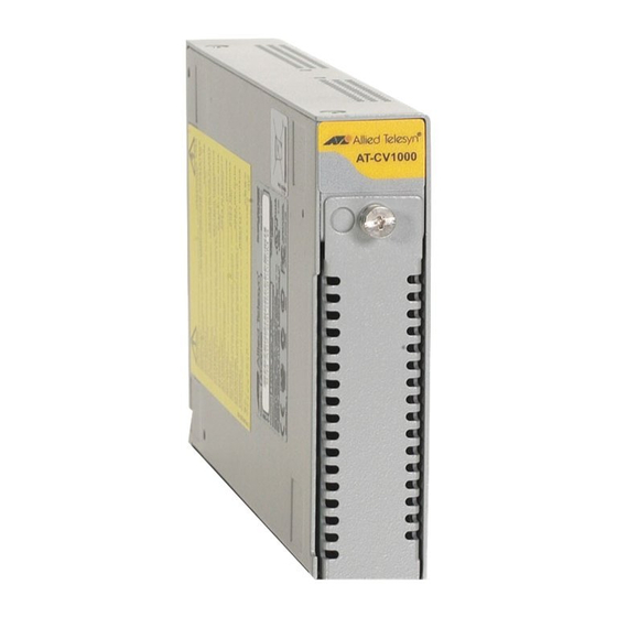
- C V Figure 1. AT-CV1000 One-Slot Converteon™ Chassis You can install the AT-CV1000 chassis on a desktop as a standalone media converter, mount it on a wall, or install it in an AT-MCR12 chassis. In addition, you can install the AT-CV1000 chassis in an AT-MCR12 media converstion rack-mount chassis. -
Page 15: Figure 2. At-Cv1000 Chassis Front And Back Panels
AT-CV1000 One-Slot Chassis Installation Guide Figure 2 shows the front and back panels of the AT-CV1000 chassis. AT-CV1000 AT-CVPNLx Blank Slot Cover AC Power Connector Figure 2. AT-CV1000 Chassis Front and Back Panels... -
Page 16: Converteon™ Line Cards
Chapter 2: Overview Converteon™ Line Cards The AT-CV1000 chassis can only house one Converteon™ line card. The line card is hot swappable. Note For a current list of Converteon™ line cards, refer to the Allied Telesis web site or consult your authorized sales representative. For detailed descriptions of these line cards, refer to the documentation shipped with the line cards and/or the Converteon™... -
Page 17: Blank Slot Cover
The AT-CV5PNL1 blank slot cover is designed to maintain optimal, trouble-free environmental conditions for the AT-CV1000 chassis. An unoccupied line card slot on the AT-CV1000 chassis should be covered with a blank slot cover to keep dust from getting into the chassis and maintain proper airflow, cooling, and ventilation throughout the chassis. -
Page 18: Power Adapter
Chapter 2: Overview Power Adapter The AT-CV1000 chassis uses a two-part AC power adapter (supplied), as shown in Figure 4. Figure 4. AC Power Adapter... -
Page 19: Network Topologies
Topology Network 1 has an AT-FS709FC switch connected to the 100Base-FX port on the AT-CM202 line card in the AT-CV1000 media converter. Network 2 has an AT-8524M switch connected to the 10/100Base-TX port on the AT-CM202 line card in the AT-CV1000 media converter. -
Page 20: Back-To-Back Topology
Network 1 has an AT-8350GB switch connected to the 10/100Base-TX port on the AT-CM202 line card in the first AT-C1000 media converter. Network 2 has an AT-8524M switch connected to the 10/100Base-TX port on the AT-CM202 line card in the second AT-CV1000 media converter. NETWORK 1... -
Page 21: Chapter 3: Installation
“Selecting a Site for the Chassis” on page 23 “Unpacking the Chassis” on page 24 “Using the AT-CV1000 Chassis on a Desktop” on page 25 “Mounting the AT-CV1000 Chassis on a Wall” on page 26 “Installing an AT-CV1000 Chassis in an AT-MCR12 Rack-Mount Chassis”... -
Page 22: Reviewing Safety Precautions
PDF document titled “Translated Safety Statements” on the Allied Telesis website at www.alliedtelesis.com and on the documentation CD shipped with this product. Warning: Do not work on equipment or cables during periods of lightning activity. -
Page 23: Selecting A Site For The Chassis
AT-CV1000 One-Slot Chassis Installation Guide Selecting a Site for the Chassis Observe the following requirements when choosing a site for the chassis: The power outlet for the chassis should be located near the unit and should be easily accessible. The site should provide easy access to the ports on the front and the power supply on the back of the chassis. -
Page 24: Unpacking The Chassis
Allied Telesis. 2. Make sure that the following components are included in the package. If any item is missing or damaged, contact your Allied Telesis sales representative for assistance. One AT-CV1000 chassis with an AT-CV5PNL1 blank slot cover... -
Page 25: Using The At-Cv1000 Chassis On A Desktop
AT-CV1000 One-Slot Chassis Installation Guide Using the AT-CV1000 Chassis on a Desktop To use the AT-CV1000 chassis on a desktop, perform the following procedure: 1. Remove the chassis from the shipping container. 2. Turn the chassis over and place it on a secure surface. -
Page 26: Mounting The At-Cv1000 Chassis On A Wall
To mount the AT-CV1000 chassis on a wall, perform the following procedure: 1. If attached, remove the rubber feet, data cables, and power cord from the chassis. -
Page 27: Figure 9. Installing The Plastic Anchors And Screws Onto The Wall
7. Position the chassis vertically onto the wall screws, as illustrated in Figure 10, and slide it down to secure the brackets against the wall. Figure 10. Positioning The AT-CV1000 Chassis Onto the Wall Screws 8. Cable the line card according to the instructions that were shipped with the line card. -
Page 28: Installing An At-Cv1000 Chassis In An At-Mcr12 Rack-Mount Chassis
Use 6 Watts of power for any MC series media converter and the AT-CV1000 with any of the Converteon line cards except the AT-CM2K0S. Use 9 Watts of power for the AT-CV1000 with an AT-CM2K0S line card installed. If the total power requirement exceeds the 80 Watt limit, then multiple AT-MCR12 rack-mount chassis are required. -
Page 29: Figure 12. Removing The Mounting Rail From A Slot In The At-Mcr12 Chassis
AT-CV1000 One-Slot Chassis Installation Guide the AT-CV1000 chassis and loosen the captive screw to remove the mounting rail from that slot, as shown in Figure 12. MEDIA CONVERTER RACKMOUNT CHASSIS 1251 Figure 12. Removing the Mounting Rail from a Slot in the AT-MCR12 Chassis 2. -
Page 30: Figure 14. At-Cv1000 Chassis With At-Cvmcr Adapter Installed
R D Y 1266 Figure 14. AT-CV1000 Chassis with AT-CVMCR Adapter Installed 5. Use the thumb tab on the adapter to slide the AT-CV1000 chassis into the AT-MCR12 chassis, as shown in Figure 15. MEDIA CONVERTER RACKMOUNT CHASSIS 2 0 2... -
Page 31: Figure 16. Tightening The Captive Screw On The At-Cvmcr Adapter
AT-CV1000 One-Slot Chassis Installation Guide 7. Tighten the captive screw on the AT-CVMCR adapter to secure the AT-CV1000 in the chassis, as shown in Figure 16. MEDIA CONVERTER RACKMOUNT CHASSIS 2 0 2 V1 00 AT -C A T -... -
Page 32: Installing A Converteon™ Line Card
Allied Telesis. 2. Loosen the captive screw to remove the AT-CV5PNL1 blank slot cover from the AT-CV1000. Keep the blank slot cover in a safe area in case you remove the line card. The blank slot cover is used to keep dust from getting into the chassis and maintains proper airflow, cooling, and ventilation through- out the chassis. -
Page 33: Figure 17. Location Of The Alignment Guides
AT-CV1000 One-Slot Chassis Installation Guide 4. Locate the alignment guides on both sides of the slot, as shown in Figure 17. AT-CV1000 Alignment Guides Figure 17. Location of the Alignment Guides 5. Align the back edge of the line card with the left and right alignment guides located inside the slot. -
Page 34: Figure 19. Tightening The Captive Screw
Chapter 3: Installation 7. Use a Phillips screwdriver to tighten the captive screw on the line card, as shown in Figure 19. - C V Figure 19. Tightening the Captive Screw Note Always tighten the captive screw to secure the line card to the chassis. -
Page 35: Powering On An At-Cv1000 Chassis
AT-CV1000 One-Slot Chassis Installation Guide Powering On an AT-CV1000 Chassis The AC power adapter for the AT-CV1000 chassis consists of two parts: a power cord and a power adapter. Note The power adapter for the AT-CV1000 chassis is not used if the chassis is installed in an AT-MCR12 rack-mount chassis. - Page 36 Chapter 3: Installation The chassis is now ready for network operations. Warning: Power cord is used as a disconnection device. To de- energize equipment, disconnect the power cord. Pluggable Equipment. The socket outlet shall be installed near the equipment and shall be easily accessible.
-
Page 37: Installing A Blank Slot Cover
AT-CV1000 One-Slot Chassis Installation Guide Installing a Blank Slot Cover The AT-CV1000 chassis is shipped with the line card slot covered with the AT-CV5PNL1 blank slot cover. When the line card slot is unoccupied, you should cover it with a blank slot cover, to keep dust from getting into the chassis and to maintain proper airflow, cooling, and ventilation throughout the chassis. -
Page 38: Figure 22. Tightening The Captive Screw On An At-Cv5Pnl1 Blank Slot Cover
Chapter 3: Installation 6. Use a Phillips screwdriver to tighten the captive screw, as shown in Figure 22. - C V Figure 22. Tightening the Captive Screw on an AT-CV5PNL1 Blank Slot Cover Note Always tighten the captive screw to secure the blank slot cover to the chassis. -
Page 39: Warranty Registration
AT-CV1000 One-Slot Chassis Installation Guide Warranty Registration... -
Page 40: Warranty Registration
Some products have a longer warranty coverage than others. The AT-CV1000 chassis has a limited warranty of Lifetime (24 months Fan & PSU). All Allied Telesis warranties are subject to the terms and conditions set out on the Allied Telesis website at www.alliedtelesis.com/warranty. -
Page 41: Appendix A: Technical Specifications
Appendix A Technical Specifications Physical Specifications Dimensions: W x D x H 10.48 cm x 17.77 cm x 2.54 cm (4.125 in x 7.0 in x 1.0 in) Environmental Specifications Operating Temperature: 0° C to 40° C (32° F to 104° F) Storage Temperature: -25°... -
Page 42: Safety And Electromagnetic Emissions Certifications
Appendix A: Technical Specifications Safety and Electromagnetic Emissions Certifications EMI: FCC Class A, EN55022 Class A, VCCI Class A, C-TICK, CE Immunity: EN55024 Safety: UL60950-1 ( ), EN60950-1 (TUV), CAN/CSA C22.2 No. 60950-1 Laser: EN60825 Quality and Reliability: MTBF > 100,000 hrs.
Need help?
Do you have a question about the AT-CV1000 and is the answer not in the manual?
Questions and answers