Table of Contents
Advertisement
Available languages
Available languages
IDROSALLY
Termostufa a pellet - Pellet Boiler-stove
Thermopoêle à pellets - Termoestufa de pellet
Wassergeführte Pellets-Heizofen - Thermokachel met pellet
Pelletvarmeovnene - Caldeiras térmicas a pellet-Termo-sobă pe peleți
I
Installazione, uso e manutenzione
UK
Installation, use and maintenance
F
Installation, usage et maintenance
E
Instalación, uso y mantenimiento
D
Installations-, Betriebs- und Wartungsanleitung
NL
Installatie, gebruik en onderhoud
DK
Installation, brug og vedligeholdelse
P
Instalação, uso e manutenção
CZ
Návod na použití, údržbu a instalaci
RO
Instalare, utilizare și întreținere
- 1
-
pag.
2
pag. 30
pag. 58
pag. 86
pag. 114
pag. 142
pag. 170
pag. 198
pag. 226
pag. 254
Advertisement
Chapters
Table of Contents

Subscribe to Our Youtube Channel
Related Manuals for EdilKamin IDROSALLY


Summary of Contents for EdilKamin IDROSALLY
- Page 1 IDROSALLY Termostufa a pellet - Pellet Boiler-stove Thermopoêle à pellets - Termoestufa de pellet Wassergeführte Pellets-Heizofen - Thermokachel met pellet Pelletvarmeovnene - Caldeiras térmicas a pellet-Termo-sobă pe peleți Installazione, uso e manutenzione pag. Installation, use and maintenance pag. 30 Installation, usage et maintenance pag.
-
Page 2: Table Of Contents
N° di SERIE: Rif. Targhetta dati Dichiarazione di prestazione (DoP - EK n° 117): Rif. Targhetta dati Altresì dichiara che: termostufa a pellet di legno IDROSALLY rispetta i requisiti delle direttive europee: 2014/35/UE - Direttiva Bassa Tensione 2014/30/UE - Direttiva Compatibilità Elettromagnetica EDILKAMIN S.p.a. - Page 3 Gentile Signora / Egregio Signore Il prodotto è identificato da un numero (tagliando di controllo) La ringraziamo e ci complimentiamo con Lei per aver scelto che trova sul certificato di garanzia. il nostro prodotto. Prima di utilizzarlo, Le chiediamo di leggere attentamente Le chiediamo di conservare : questa scheda, al fine di poterne sfruttare al meglio ed in •...
-
Page 4: Informazioni Per La Sicurezza
• Assicurarsi che l’istallazione e la 1° accensione vengano all’introduzione di sostanze estranee, a combustibili non racco- eseguite da CAT abilitato Edilkamin (centro assistenza tecnica) mandati, a una non corretta manutenzione, al ripetuto aziona- secondo le indicazioni della presente scheda; condizioni peral- mento del tasto di accensione senza aver svuotato il crogiolo. -
Page 5: Informazioni Generali
INFORMAZIONI GENERALI La termostufa utilizza come combustibile il pellet, costituito da piccoli cilindretti di legno pressato, la cui combustione viene gestita elettronicamente. La termostufa è in grado di riscaldare l’acqua per alimentare l’impianto di riscaldamento (termosifoni, scalda salviette, pannelli radianti a pavimento) ed inoltre produce aria calda, tramite un ventilatore, per riscaldare il locale di installazione. - Page 6 INFORMAZIONI GENERALI • APPARATI ELETTRONICI LEONARDO è un sistema di sicurezza e regolazione della combustione che consente un funzionamento ottimale in qualunque condizione grazie a due sensori che rilevano il livello di pressione nella camera di combustione e la temperatura dei fumi. La rilevazione e la conseguente ottimizzazione dei due parametri avviene in continuo in modo da correggere in tempo reale eventuali anomalie di funzionamento.
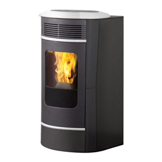
- Page 7 INFORMAZIONI GENERALI LA TERMOSTUFA È PRODOTTA IN SEI VARIANTI ESTETICHE: - acciaio grigio scuro con inserti e top in ceramica bianco panna - acciaio grigio scuro con inserti e top in ceramica rossa - acciaio grigio scuro con inserti e top in ceramica grigia - ceramica bianco panna - ceramica rossa - ceramica pergamena...
- Page 8 800 Va a onde sinusoidali. Variazione maggiori del 10% di alimentazione possono provocare problemi al prodotto. I dati sopra riportati sono indicativi e rilevati in fase di certificazione presso organismo certificato. EDILKAMIN s.p.a. si riserva di modificare i prodotti senza preavviso e a suo insindacabile giudizio.
- Page 9 INFORMAZIONI GENERALI • COMPONENTI - DISPOSITIVI DI SICUREZZA E RILEVAZIONE Termocoppia fumi Pompa (circolatore elettronico - vedi pag. 23) Posta sullo scarico fumi, ne legge la temperatura. “Spinge” l’acqua verso l’impianto di riscaldamento. Regola la fase di accensione e in caso di temperatura troppo bassa o troppo alta lancia una fase di blocco.
-
Page 10: Installazione
La non efficienza del circuito di terra provoca mal funziona- mento di cui Edilkamin non si potrà far carico. In caso di problemi alla rete elettrica consultare un elettricista per valutare l’installazione di un gruppo di continuità di almeno 800 Va a onde sinusoidali. - Page 11 INSTALLAZIONE CASI TIPICI SCARICO FUMI Fig. 1 Fig. 2 Il sistema di scarico deve essere unico per la termostufa (non si ammettono scarichi in canna fumaria comune con altri dispositivi). Lo scarico dei fumi avviene dal tubo di diametro 8 cm posto sul retro della termostufa.
- Page 12 è posizionato il KIT. • Di seguito sono riportati alcuni schemi “tipici” che Edilkamin - Deve avere uno sviluppo verticale non minore di 30 cm. mette a disposizione.
- Page 13 N.B.: I presenti schemi sono indicativi, la corretta esecuzione è a cura dell’idraulico. ACCESSORI: Negli schemi sopra riportati è stato previsto l’impiego di accessori disponibili a listino EDILKAMIN S.p.A.. Sono inoltre disponibili parti sciolte (scambiatore, valvole, ecc.), rivolgersi al rivenditore di zona.
-
Page 14: Montaggio Rivestimento
MONTAGGIO RIVESTIMENTO 1) VERSIONE CON FIANCHI E TOP IN fig. 1 CERAMICA Fig. 1 La stufa viene consegnata (fig. 1) con i seguenti componenti esterni già montati: • fianchi metallici (A-B) • telai metallici per il fissaggio degli elementi laterali in cerami- ca (C) •... - Page 15 MONTAGGIO RIVESTIMENTO Fig. 4 fig. 4 Applicare sul retro del frontalino inferiore in ceramica (G), le molette (G1) di fissaggio utilizzando i fori previsti e n° 4 viti M4 in dotazione. N.B.: le molette devono essere montate con la battuta verso l’esterno come da particolare in figura 4.
- Page 16 MONTAGGIO RIVESTIMENTO Fig. 7 fig. 7 Avvitare leggermente i 2 perni zigrinati M4 in dotazione sul retro dell’elemento superiore in ceramica (H). Fig. 8 fig. 8 Aprire l’antina e inserire sulle asole presenti sul frontalino metallico superiore (E) l’elemento superiore in ceramica (H) completo di perni zigrinati e serrare manualmente.
- Page 17 MONTAGGIO RIVESTIMENTO 2) VERSIONE CON FIANCHI IN ACCIAIO E fig. 10 PROFILI E TOP IN CERAMICA Fig. 10 La stufa viene consegnata (fig. 1) con i fianchi metallici (A-B) e i frontali metallici inferiori/superiori (D - E) già montati. I pezzi sottoindicati sono invece imballati a parte. •...
-
Page 18: Istruzioni D'uso
Detta norma indica le operazioni di controllo da eseguire sul posto, finalizzate ad accertare il corretto funzionamento del sistema. L’assistenza tecnica Edilkamin (CAT), avrà cura anche di tarare la termostufa in base al tipo di pellet e alle condizioni di instal- lazione (es: caratteristiche della canna fumaria). - Page 19 ISTRUZIONI D’USO RADIOCOMANDO Serve per gestire tutte le funzioni per l’utilizzo. Legenda tasti e display: : per accendere e spegnere (per passare da radiocomando stand by a radiocomando attivo) +/- : per incrementare / decrementare le diverse regolazioni : Tasto AIR : regola il funzionamento della ventilazione in OFF- AUTO o manuale F1,F2,F3,F4,F5 M : Tasto MENU’: premuto brevemente per impostatre le modalità...
- Page 20 ISTRUZIONI D’USO Riempimento coclea. OPERAZIONI EFFETTUABILI SOLO CON RADIOCO- MANDO Al primo utilizzo o in caso di svuotamento completo del serba- Regolazione orologio toio del pellet, per riempire la coclea premere contemporanea- Premendo per 2” il tasto “M” si accede al Menù “Orologio” mente i tasti “+”...
- Page 21 50 ad 80°C; se diversamente era impo- Edilkamin non risponderà in alcun modo di variazioni rispetto stata in comfort clima, si varia incrementando ciclicamente la all’indicato (può dipendere da fattori esterni).
- Page 22 ISTRUZIONI D’USO IL CIRCOLATORE ELETTRONICO Sintetizziamo i segnali che i circolatori a basso consumo posso- (pompa a basso consumo) no mostrare col led posto sulla centralina della pompa stessa Il prodotto è dotato di un circolatore con motore elettronico per contenere i consumi elettrici e rispettare le normative Europee.
-
Page 23: Manutenzione
MANUTENZIONE Prima di effettuare qualsiasi manutenzione, scollegare l’ap- parecchio dalla rete di alimentazione elettrica. Una regolare manutenzione è alla base del buon funziona- mento della termostufa. Eventuali problemi dovuti alla mancata manutenzione sono causa di decadenza della garanzia. In caso di necessità URGENTE di pulizia dello scambiatore sul pannello appare la scritta Pulire -scam.re”. - Page 24 MANUTENZIONE MANUTENZIONE STAGIONALE (a cura CAT - centro assistenza tecnica autorizzato Edilkamin) • Pulizia generale interna ed esterna • Pulizia accurata dei tubi di scambio • Pulizia accurata e disincrostazione del crogiolo e del relativo vano • Pulizia ventilatori, verifica meccanica dei giochi e dei fissaggi •...
-
Page 25: Consigli Per Possibili Inconvenienti
CONSIGLI PER POSSIBILI INCONVENIENTI In caso di problemi la termostufa si arresta automaticamente attivando l’operazione di spegnimento e sul display si visua- lizza una scritta relativa alla motivazione dello spegnimento (vedi sotto le varie segnalazioni). Non staccare mai la spina durante la fase di spegnimento per blocco. Nel caso di avvenuto blocco, per riavviare la stufa è... - Page 26 CONSIGLI PER POSSIBILI INCONVENIENTI 7) Segnalazione: °C fumi/alta (spegnimento per eccessiva temperatura dei fumi) Inconveniente: Spegnimento per superamento temperatura massima fumi. Azioni: Verificare: • tipo di pellet (in caso di dubbi chiamare CAT) • anomalia estrazione fumi (CAT) • canale fumi ostruito, installazione non corretta (CAT) •...
- Page 27 - Richiedere l’intervento dei Vigili del fuoco NON TENTARE DI SPEGNERE IL FUOCO CON ACQUA! Successivamente richiedere la verifica dell’apparrecchio da parte di un Centro di Assistenza Tecnica Autorizzato Edilkamin e far verificare la canna fumaria da un tecnico autorizzato.
-
Page 28: Faq
Le risposte sono qui riportate in forma sintetica; per maggiori dettagli consultare le altre pagine del presente documento. 1) Cosa devo predisporre per poter installare la termostufa? Scarico fumi di almeno 80 mm di diametro o un collegamneto diretto con l’esterno. Presa aria di almeno 80 cm²... -
Page 29: Check List
CHECK LIST Da integrare con la lettura completa della scheda tecnica Posa e installazione • Messa in servizio effettuata da CAT abilitato che ha rilasciato la garanzia • Presa d’aria nel locale • Il canale da fumo/la canna fumaria riceve solo lo scarico della termostufa •... - Page 30 Possible troubleshooting ..........pag. 53 Faq ................pag. 56 Check list ..............pag. 57 The undersigned EDILKAMIN S.p.a. with head office headquar- ters at Via Vincenzo Monti 47 - 20123 Milan - Italy - VAT IT00192220192 Declares under its own responsability as follows:...
-
Page 31: Note
You will need to present a copy of the warranty booklet and valid proof of purchase. - Commissioning/ testing This must be carried out by an EDILKAMIN authorised Technical Assistance Centre (TAC) to guarantee proper operation. Commissioning, as specified in standard UNI 10683 consists in a series inspections to be performed with the boiler-stove installed in order to ascertain the correct operation of the system and its compliance to applicable regulations. -
Page 32: Safety Information
• Make sure the boiler-stove is installed and ignited the first pertain to non-compliance with installation instructions, direct time by Edilkamin-qualified CAT personnel (technical assistan- contact with live electrical parts (internal), contact with the ce centre) in accordance with the instructions provided here fire or hot parts (glass, pipes, hot air output), when extraneous within;... -
Page 33: General Information
GENERAL INFORMATION The boiler-stove is fuelled by pellets. These are little, cylin- drical shapes of pressed wood whose combustion is controlled electronically. The thermo-stove is able to heat water to feed the heating system (radiators, heated towel rails, and underfloor heating panels), as well as producing hot air with a fan to heat the room in which it is installed. - Page 34 GENERAL INFORMATION • ELECTRONIC CIRCUIT BOARD LEONARDO is a combustion safety and control system which allows optimal performan- ce in all conditions thanks to two sensors measuring the pressure level in the combustion chamber and smoke temperature. The detection of and subsequent optimisation of these two parameters is continuous in order to correct operation anomalies in real time.
- Page 35 GENERAL INFORMATION THE IDROSALLYIS PRODUCED IN SIX DIFFERENT FINISHES: - dark grey steel with cream white ceramic inserts and top - dark grey steel with red ceramic inserts and top - dark grey steel with grey ceramic inserts and top - cream white ceramic - red ceramic - parchment ceramic...
- Page 36 800 Va. Power variations greater than 10% can cause problems for the product. The above data are indicative and are those resulting during certification on the part of the notified body. EDILKAMIN s.p.a. reserves the right to change the products at its discretion without notice. - 36...
- Page 37 GENERAL INFORMATION • COMPONENTS - SAFETY AND DETECTION DEVICES Smoke thermocouple Pump (electronic circulator - see page. 53) on the smoke outlet. It reads the smoke temperature. It regula- “Pushes” water toward the heating system. tes the ignition stage and shuts the boiler-fireplace down if the temperature is too high or too low.
-
Page 38: Installation
The power line must have a suitable cross-section for the boiler power. An inadequate earthing system can cause anomalies for which Edilkamin cannot be held liable. In case of problems with the electrical grid, consult an electri- cian to evaluate the installation of a sine-wave UPS of at least 800 Va. - Page 39 INSTALLATION SMOKE OUTLET TYPICAL EXAMPLES The boiler-stove must have its own smoke outlet (the smoke Fig. 1 Fig. 2 cannot be discharged into a smoke flue used by other devices). The smoke is discharged through the 8 cm diameter outlet at the back of the boiler A T-junction must be set up with a condensation collection stopper at the beginning of the vertical section.
- Page 40 • Below are several diagrams of “typical” installations provided - Must not originate more than 50 cm from the discharge of the by Edilkamin. valve and must be positioned in the same room where the KIT The accessories for their implementation are available from your is positioned.
- Page 41 This layout is purely indicative. Have a plumber design and install the system. ACCESSORIES: In the diagram shown above, the use of the accessories available on the EDILKAMIN S.p.A. pricelist is assumed. Individual spare parts are also available (exchanger, valves, etc). For information, please contact your local dealer.
-
Page 42: Covering Installation
COVERING INSTALLATION 1) VERSION WITH CERAMIC SIDES AND fig. 1 Fig. 1 The stove is delivered (Fig. 1) with the following external com- ponents already installed: • metal sides (A-B) • metal frames for fastening the ceramic side elements (C) •... - Page 43 COVERING INSTALLATION Fig. 4 fig. 4 Fit the fastening springs (G1) on the back of the lower ceramic front piece (G) using the holes and 4 M4 screws provided. Note: the springs must be mounted with the strike plate facing outwards as detailed in Figure 4.
- Page 44 COVERING INSTALLATION Fig. 7 fig. 7 Lightly tighten the 2 milled M4 pins provided on the back of the upper ceramic element (H). Fig. 8 fig. 8 Open the door and insert the upper ceramic element (H), complete with milled pins, on the slots on the upper metal front piece (E) and tighten by hand.
- Page 45 COVERING INSTALLATION 2) VERSION WITH STEEL SIDES AND CERA- fig. 10 MIC PROFILES AND TOP Fig. 10 The stove is delivered (Fig. 1) with the metal side (A-B) and the metal lower/upper front parts (D-E) already mounted. The pieces indicated below are packaged separately. •...
-
Page 46: Instructions For Use
This standard indicates the control operations to be carried out in situ, aimed at ascertaining correct system function. Edilkamin’s Technical Assistance staff (CAT) will also cali- brate the boiler-stove based on the pellet type used and the installation conditions (e.g. features of the flue). - Page 47 INSTRUCTIONS FOR USE REMOTE CONTROL This controls all the functions. Key to buttons and display: : to turn off and on (to go from “remote control on standby” to “remote control on”) +/- : to increase/decrease the various regulations : AIR key: to adjust the functioning of the fan in OFF- AUTO or manual mode F1, F2, F3, F4, F5 M : MENU’...
- Page 48 INSTRUCTIONS FOR USE Filling the cochlea. OPERATIONS THAT CAN ONLY BE CARRIED OUT BY REMOTE CONTROL The first time you use the product, or should the tank be com- Clock regulation pletely emptied of pellets, to fill the coclea press both keys “+” Press and hold the key “M”...
- Page 49 Greater precision is obtained by regularly zeroing the system 4. BOILER-STOVE ON before filling it again. Edilkamin does not accept any responsi- If the stove is set in power mode, press it quickly to change the bility for differences from what is indicated (which may be due SET output, increa¬sing it cyclically from 50 to 80°C;...
- Page 50 INSTRUCTIONS FOR USE THE ELECTRONIC CIRCULATOR We summarize the signals that low-consumption circulators (low-consumption pump) can display with the LEDs located on the pump controls The product has a circulator with an electronic motor to save electricity and comply with the European regulations. The led The green The led...
-
Page 51: Maintenance
MAINTENANCE Before performing any maintenance, disconnect the applian- ce from the mains. Regular maintenance is required for the boiler-stove to fun- ction correctly. Any problems resulting from lack of maintenance will imme- diately void the warranty. When cleaning is necessary, the message “Clean - exchan- ger”... - Page 52 MAINTENANCE SEAS ONAL MAINTE NANCE (implemented by the DEALER ) Consists in: • Clean the boiler-stove internally and externally • Carefully clean the heat exchange tubes • Carefully clean and remove dirt from the combustion chamber and the relative compartment •...
-
Page 53: Possible Troubleshooting
POSSIBLE TROUBLESHOOTING In the event of problems the boiler-stove stops automatically and runs the shutdown process and the display shows text regarding the motivation of the shutdown (see the various alarms below). Never pull the plug during shutdown on account of malfunction. To start the boiler-stove up again after a shutdown, let the shutdown procedure end (10 minutes marked by a beep) tand then press the button Do not turn the boiler-stove on again before checking the cause of the malfunction and CLEANING/ EMPTYING the... - Page 54 POSSIBLE TROUBLESHOOTING 7) Signalling: smoke °C/high.: (turns off due to exceeding maximum smoke temperature). Problem: Switching off due to exceeding the maximum smoke temperature. Check (only by the Dealer): • pellet type, anomaly in smoke extraction, • smoke channel blocked, •...
- Page 55 POSSIBLE TROUBLESHOOTING 15) Problem: During ignition, the differential switch trips (DEALER): Actions: • Check the condition of the ignition coil, the electrical system, and the electrical components. 16) Problem: Water is not hot enough: Actions: • clean the hearth exchanger NOTE 1 All signals/warnings remain shown until you intervene on the remote control, by pressing the button Do not use the insert before having eliminated the problem.
-
Page 56: Faq
The answers are listed below in summary form, for further details see the other pages of this document. 1) What do I need to prepare in order to install the boiler-stove? Flue pipe at least 80 mm in diameter or direct connection to the outside. An air inlet in the room that is at least 80 cm². -
Page 57: Check List
CHECK LIST To be integrated with a complete reading of the technical specifications Positioning and installation • Commissioning done by an approved CAT that issued the guarantee • Air vent in the room • Only the boiler-stove outlet passes through the smoke channel/chimney flue •... - Page 58 Inconvenients possibles ..........pag. 81 Faq ................pag. 84 Check list ..............pag. 85 La societé EDILKAMIN S.p.A. ayant son siège légal à Via Vin- cenzo Monti 47 - 20123 Milan - Code Fiscal P.IVA 00192220192 Déclare sous sa propre responsabilité: Le thermopoêle à...
- Page 59 - Mise en service/test Elle doit être absolument effectuée par le Centre d’Assistance Technique (CAT) agréé par EDILKAMIN, afin de garantir un bon fonctionnement. La mise en service ainsi qu’elle est décrite dans par la norme UNI 10683 consiste en une série d’opérations de de contrôle effectuées lorsque le poêle est installé...
-
Page 60: Informations Pour La Securite
• S’assurer que le poêle soit positionné et allumé par un CAT chaud) à l’introduction de substances étrangères, à des com- autorisé Edilkamin (centre d’assistance technique) selon les bustibles non recommandés, à un entretien non approprié ou indications de la présente fiche; conditions du reste indispensa- actionnement répété... -
Page 61: Informations Générales
INFORMATIONS GÉNÉRALES Le thermopoêle utilise comme combustible le pellet, constitué de petits cylindres en matériau ligneux comprimé, et sa combu- stion est gérée électroniquement. La poêle thermique est en mesure de chauffer l’eau pour alimenter l’installation de chauffage (radiateurs, chauffe- serviettes, panneaux chauffants au sol) et de produire de l’air chaud, grâce à... - Page 62 INFORMATIONS GÉNÉRALES • APPAREILS ÉLECTRONIQUES LEONARDO est un système de sécurité et de réglage de la combustion qui permet un fon- ctionnement optimal quelles que soient les conditions grâce à deux capteurs qui relèvent le niveau de pression dans la chambre de combustion et la température des fumées. Ces deux paramètres sont relevés et par conséquent optimisés en continu de manière à...
- Page 63 INFORMATIONS GÉNÉRALES LE THERMOPOÊLE EST DISPONIBLE DANS SIX VARIANTES ESTHÉTIQUES : - acier gris foncé avec inserts et top en céramique blanc crème - acier gris foncé avec inserts et top en céramique rouge - acier gris foncé avec inserts et top en céramique grise - céramique blanc crème - céramique rouge - céramique parchemin...
- Page 64 INFORMATIONS GÉNÉRALES CARACTÉRISTIQUES THERMOTECHNIQUES en conformité avec EN 14785 Puissance nominal Puissance réduite Puissance thermique utile 16,2 Puissance thermique transmise à l’eau sans ventilateur 11,8 Puissance thermique transmise à l'environnement Rendement / Performance 91,6 97,6 Émissions CO 13% O 0,010 0,025 Température des fumées °C...
- Page 65 INFORMATIONS GÉNÉRALES • COMPOSANTS - DISPOSITIFS DE SECURITE ET DE DETECTION Le Circulateur (circulateur electronique - voir page 83) Thermocouple fumées placé sur l’évacuation des fumées, il en lit la température. Il “Envoi “ l’eau vers l’installation de chauffage. règle la phase d’allumage et, en cas de température trop basse ou trop haute, il lance une phase de blocage.
-
Page 66: Installation
à la puissan- ce de l’appareil. Le mauvais état de marche du circuit de terre provoque un mauvais fonctionnement qu’Edilkamin ne peut prendre en charge. En cas de problèmes sur le réseau électrique, consultez un électricien pour évaluer l’installation d’une alimentation sans... - Page 67 INSTALLATION EVACUATION DES FUMÉES CAS TYPIQUES Le système d’évacuation doit être unique pour le thermo- Fig. 1 Fig. 2 poêle (des conduits d’évacuation dans un conduit de che- minée commun à d’autres dispositifs n’est pas acceptable). L’évacuation des fumées se fait par le tuyau de 8 cm de diamètre situé...
- Page 68 Inail, du mois d’avril 2011). Cette séparation se fait facilement Pendant la phase de chargement faire “ purger “ la pompe et le à l’aide du KIT A2 Edilkamin. robinet de purge. • La présence d’un ballon tampon (accumulation inertielle) est •...
- Page 69 Ce schéma est indicatif, l’installation correcte est aux soins du plombier. ACCESSOIRES: Les schémas ci-dessus ont prévu l’utilisation d’accessoires figurant dans le catalogue EDILKAMIN S.p.A. En outre des éléments au détail sont disponibles (échangeur, soupapes, etc...). Pour toute information s’adresser à son revendeur.
-
Page 70: Montage Revêtement
MONTAGE REVÊTEMENT 1) VERSION AVEC CÔTÉS ET TOP EN fig. 1 CÉRAMIQUE Fig. 1 Le poêle est livré (fig. 1) avec les composants externes déjà installés : • côtés métalliques (A-B) • cadres métalliques pour la fixation des éléments latéraux en céramique (C) •... - Page 71 MONTAGE REVÊTEMENT Fig. 4 fig. 4 Appliquer sur l’arrière de la façade inférieure en céramique (G) les ressorts (G1) de fixation, en utilisant les trous prévus et les 4 vis M4 fournies. N.B. : monter les ressorts avec la butée vers l’extérieur, comme indiqué...
- Page 72 MONTAGE REVÊTEMENT Fig. 7 fig. 7 Serrer légèrement les 2 goujons moletés M4 fournis sur l’arrière de l’élément supérieur en céramique (H). Fig. 8 fig. 8 Ouvrir la porte et insérer dans les fentes sur la façade métallique supérieure (E) l’élément supérieur en céramique (H) avec les goujons moletés, puis serrer à...
- Page 73 MONTAGE REVÊTEMENT 2) VERSION AVEC CÔTÉS EN ACIER ET fig. 10 PROFILS ET TOP EN CÉRAMIQUE Fig. 10 Le poêle est livré (fig. 1) avec les côtés métalliques (A-B) et les façades métalliques inférieures/supérieures (D-E) déjà montés. Les pièces indiquées ci-dessous sont en revanche emballées à part.
-
Page 74: Instructions D'utilisation
Une simple analyse du pellet peut être faite visuellement : la garantie. Bonne qualité: lisse, longueur régulière, peu poudreux. Edilkamin a conçu, testé et programmé ses produits afin qu’ils Mauvaise qualité: fentes longitudinales et transversales, très garantissent les meilleures prestations avec du pellet aux ca- poudreux, longueur très variable et avec présence de corps... - Page 75 INSTRUCTIONS D’UTILISATION RADIOCOMMANDE Elle sert à gérer toutes les fonctions. Légende touches et display: : pour allumer et éteindre (pour passer de la radiocommande en stand by à la radiocommande active) +/- : pour augmenter /baisser les différents réglages : Touche AIR : permet de régler le fonctionnement de la ventilation en OFF-AUTO ou en manuel F1, F2, F3, F4, F5. M : Touche MENU : appuyer brièvement pour paramétrer les modes de fonctionnement confort climat ou régulation des puis- sances;...
- Page 76 INSTRUCTIONS D’UTILISATION Remplissage vis sans fin. OPÉRATIONS EFFECTUÉES UNIQUEMENT AVEC RADIOCOMMANDE Lors de la première utilisation ou en cas de vidage complet du Réglage horloge réservoir à pellet, pour remplir la vis sans fin, appuyer en même En appuyant pendant 2” sur la touche “M”, on accède au menu temps sur les touches “+”...
- Page 77 à zéro avant d’effectuer le nouveau chargement. en appuyant brièvement sur le bouton, on varie le réglage de la Edilkamin ne répondra, en aucune manière, en cas de varia- température de refoulement de consigne, en l’augmentant cycli- tion par rapport à ce qui a été indiqué (cela peut dépendre de quement de 50 à...
- Page 78 INSTRUCTIONS D’UTILISATION LE CIRCULATEUR ELECTRONIQUE Nous synthétisons les signaux que les circulateurs à faible (pompe à faible consommation) consommation peuvent indiquer avec la LED qui se trouve sur Le produit est équipé d’un circulateur avec un moteur électro- la centrale de la pompe. nique pour réduire la consommation d’énergie et respecter les normes européennes.
-
Page 79: Entretien
ENTRETIEN Avant d’effectuer toute manutention, débrancher l’appareil du réseau d’alimentation électrique. Un entretien régulier est la base du bon fonctionnement du thermopoêle. D’éventuels problèmes dus à l’absence d’entretien entraine- ront l’expiration de la garantie. Si un nettoyage est nécessaire, le message « Nettoyer - échang. - Page 80 ENTRETIEN ENTRET IEN SA ISONNIER (par le revendeur) • Nettoyage général interne et externe • Nettoyage soigneux des conduits d’échange • Nettoyage soigneux et désincrustation du creuset et de sa niche • Nettoyage des moteurs, vérification mécanique des jeux et des fixations •...
-
Page 81: Inconvenients Possibles
INCONVENIENTS POSSIBLES In cas de problème, thermopoêle s’arrête automatiquement en effectuant l’opération d’extinction, et à l’écran s’affiche une indication relative à la raison de l’extinction (voir les divers signalements ci-dessous). Ne jamais débrancher la fiche durant la phase d’extinction pour motif de blocage. En cas de blocage, pour redémarrer le thermopoêle, il faut le laisser s’arrêter (600 secondes avec signal sonore) puis ap- puyer sur la touche Ne pas rallumer le thermopoêle avant d’avoir vérifié... - Page 82 INCONVENIENTS POSSIBLES 7) Signalisation: °C fumées élevée: (extinction pour température excessive des fumées) Inconvénient: arrêt pour dépassement de la température maximum des fumées. Vérifier (Revendeur): • type de pellet, anomalie extraction des fumées • conduit des fumées obstrué • installation incorrecte •...
- Page 83 INCONVENIENTS POSSIBLES 15) Inconvénient: Pendant la phase d’allumage “ le différentiel saute “ (pour le revendeur) Actions: • Vérifier les conditions de la résistance d’allumage, de l’installation électrique et des composants électriques. 16) Inconvénient: Eau non suffisamment chaude: Actions: • Nettoyer l’échangeur de l’intérieur du foyer REMARQUE 1 Tous les signalements restent affichés jusqu’à...
-
Page 84: Faq
Les réponses sont indiquées ci-dessous sous forme synthétique ; pour plus de détails, consulter les autres pages de ce document. 1) Que dois-je préparer pour pouvoir installer les thermopoêle? Échappement des fumées avec diamètre minimum de 80 mm Prise d’air dans la pièce d’au moins 80 cm² ou raccordement direct avec l’extérieur. Fixation refoulement et retour au collecteur ¾”... -
Page 85: Check List
CHECK LIST A intégrer avec la lecture complète de la fiche technique Pose et installation • Mise en service effectuée par le CAT certifié ayant délivré la garantie • Prise d’air dans la pièce • Le conduit de fumées/conduit de cheminée reçoit seulement l’évacuation du themopoêle •... - Page 86 N° de SERIE: Ref. Etiqueta datos Declaración de prestación (DoP - EK n° 117): Ref. Etiqueta de datos Asimismo declara que: La termoestufa de pellet de leña IDROSALLY respeta los requisi- tos de las directivas europeas: – Directiva Baja Tensión 2014/35/CE –...
- Page 87 A través del distribuidor, la página web www.edilkamin.com o el número gratuito, puede encontrar el Centro de Asistencia más cercano.
-
Page 88: Informaciones De Seguridad
• Asegurarse de que la termoestufa es colocada y encendida por o con un contacto con fuego y partes calientes (vidrio, tubos, el VENDEDOR habilitado Edilkamin (según las indicaciones salida de aire caliente) a la introducción de sustancias extrañas, de esta ficha; condiciones indispensables para la validez de la a combustibles no recomendados, a un mantenimiento no cor- garantía. -
Page 89: Información General
INFORMACIÓN GENERAL La termoestufa utiliza como combustible el pellet, constituido por pequeños cilindros de material leñoso prensado, cuya com- bustión se gestiona electrónicamente. La termoestufa es capaz de calentar el agua para alimentar el sistema de calefacción (radiadores, calientatoallas, paneles ra- diantes de pavimento) y además produce aire caliente, median- te un ventilador, para calentar el local donde está... - Page 90 INFORMACIÓN GENERAL • APARATOS ELECTRÓNICOS LEONARDO es un sistema de seguridad y regulación de la combustión que permite un funcionamiento óptimo en cualquier condición gracias a dos sensores que detectan el nivel de presión en la cámara de combustión y la temperatura de los humos. La detección y la consiguiente optimización de los dos parámetros se efectúan en conti- nuo para corregir en tiempo real posibles anomalías de funcionamiento.
- Page 91 INFORMACIÓN GENERAL LA TERMOESTUFA SE FABRICA EN SEIS VARIANTES ESTÉTICAS - acero gris oscuro con insertables y top de cerámica blanca crema - acero gris oscuro con insertables y top de cerámica roja - acero gris oscuro con insertables y top de cerámica gris - cerámica blanca crema - cerámica roja - cerámica pergamino...
- Page 92 Los datos anteriores son indicativos y se han detectado en la fase de certificación ante el organismo notificado. EDILKAMIN s.p.a. se reserva el derecho de modificar sin previo aviso los productos y a su entero juicio - 92...
- Page 93 INFORMACIÓN GENERAL • COMPONENTES - DISPOSITIVOS DE SEGURIDAD Y ALERTA Termocupla humos Pompa (circulador electrónico - ver pag. 113) situada en la descarga de humos, lee su temperatura. Regula la “empuja” el agua hacia la instalación de calefacción. fase de encendido y en caso de temperatura demasiado baja o demasiado alta lanza una fase de bloqueo.
-
Page 94: Instalación
La ineficiencia del circuito de tierra provoca el mal funcionamiento del cual Edilkamin no se hace responsable. En caso de problemas en la red eléctrica, consultar con un electricista para considerar la instalación de un sistema de... - Page 95 INSTALACIÓN DESCARGA DE HUMOS CASOS TÍPICOS El sistema de descarga de humos debe ser único para la Fig. 1 Fig. 2 termoestufa (no se admiten descargas en salida de humos común a otros dispositivos). La descarga de humos se realiza desde el tubo de diámetro 8 cm situado en la parte posterior.
- Page 96 - Debe tener un desarrollo vertical de al menos 30 cm. • A continuación se muestran algunos esquemas “típicos” que Después la tubería puede proseguir horizontalmente con una pone a disposición Edilkamin. pendiente que favorezca el flujo de agua. Los accesorios para su realización se pueden encontrar en las tiendas autorizadas.
- Page 97 El siguiente esquema sólo es a nivel indicativo, la correcta instalación debe realizarse por personal especializado. ACCESORIOS: En los esquemas antes indicados se ha previsto el uso de accesorios disponibles en en catálogo EDILKAMIN S.p.A. Además, hay disponibles partes sueltas (intercambiador, válvulas, etc) Para cualquier información contactar al vendedor de zona.
-
Page 98: Montaje Revestimientos
MONTAJE REVESTIMIENTOS 1) VERSIÓN CON LATERALES Y TOP DE fig. 1 CERÁMICA Fig. 1 La estufa se entrega (fig. 1) con los siguientes componentes externos ya montados: • laterales metálicos (A-B) • bastidores metálicos para la fijación de los elementos laterales de cerámica (C) •... - Page 99 MONTAJE REVESTIMIENTOS Fig. 4 fig. 4 Aplicar las pinzas de fijación (G1) en la parte trasera del frontal inferior de cerámica (G) utilizando los orificios previstos y 4 tornillos M4 en dotación. N.B.: las pinzas deben montarse con el hueco abierto hacia el exterior como se indica en la figura 4.
- Page 100 MONTAJE REVESTIMIENTOS Fig. 7 fig. 7 Atornillar ligeramente los 2 pernos estriados M4 en dotación en la parte trasera del elemento superior de cerámica (H). Fig. 8 fig. 8 Abrir la puerta, introducir el elemento superior de cerámica (H) provisto de pernos estriados en las ranuras presentes en el frontal metálico superior (E) y apretar manualmente.
- Page 101 MONTAJE REVESTIMIENTOS 2) VERSIÓN CON LATERALES DE ACERO Y fig. 10 PERFILES Y TOP DE CERÁMICA Fig. 10 La estufa se entrega (fig. 1) con los laterales metálicos (A-B) y los frontales metálicos inferiores/superiores (D - E) ya monta- dos. Por su parte, las piezas siguientes se embalan aparte: •...
- Page 102 (incluida leña), detectable a través de análisis de simple análisis del pellet puede llevarse a cabo visualmente. laboratorio, dejaría sin efecto la garantía. EdilKamin ha pro- Bueno: Liso, longitud regular, poco polvoroso. yectado, probado y programado sus propios productos para que...
-
Page 103: Instrucciones De Uso
INSTRUCCIONES DE USO MANDO A DISTANCIA Sirve para controlar todas las funciones. Leyenda teclas y pantalla: : para encender y apagar (para pasar de mando a distancia stand by a mandos a distancia activo) +/- : para aumentar / disminuir las distintas regulaciones : Tecla AIR: regula el funcionamiento de la ventilación en OFF- AUTO o manual F1,F2,F3,F4,F5 M : Tecla de MENÚ: se pulsa de forma breve para configurar los modos de funcionamiento confort clima o modular potencias;... - Page 104 INSTRUCCIONES DE USO Llenado cóclea. OPERACIONES EFECTUADAS SOLO CON MANDO A En el primer uso o en caso de vaciado completo del depósito de DISTANCIA pellet, para llenar la cóclea presionar las teclas “+” y “—” del Regulación del reloj mando a distancia contemporáneamente, durante algún segun- Presionando durante 2”...
- Page 105 50 a 80°C; si estaba Edilkamin no responde de ninguna manera en caso de variacio- configu¬rada en confort clima, se varía aumentando cíclica- nes con respecto a cuanto indicado (puede depender de factores mente la temperatura deseada en ambiente de 10 a 30°C.
- Page 106 INSTRUCCIONES DE USO EL CIRCULADOR ELECTRÓNICO Sinteticemos las señales que pueden mostrar las bombas de bajo (bomba de bajo consumo) consumo con el led situado en la centralita de dicha bomba. El producto cuenta con una bomba con motor electrónico para limitar el consumo eléctrico y respetar las normativas europeas.
-
Page 107: Manutención
MANUTENCIÓN Antes de realizar cualquier mantenimiento, desenchufar el aparato de la red de alimentación eléctrica. Un mantenimiento regular es la base de un buen funciona- miento de la termoestufa. Posibles problemas debidos a la falta de mantenimiento harán que decaiga la garantía. En caso de necesidad de limpieza, en el panel aparece el men- saje “Limpiar -scam.re”. - Page 108 MANUTENCIÓN MANTENIMIENTO ESTACIONAL (a cargo del distribuidor) • Limpieza general interior y exterior. • Limpieza profunda de los tubos de intercambio. • Limpieza profunda y desincrustación del crisol y de su relativo espacio. • Limpieza motores, comprobación mecánica de los juegos y de las fijaciones.
-
Page 109: Posibles Inconvenientes
POSIBLES INCONVENIENTES En caso de problemas la termoestufa se para automáticamente efectuando la operación de apagado y en la pantalla se visualiza una anotación relativa a la motivación del apagado (ver debajo las diferentes señalizaciones). No desconecte nunca el enchufe durante la fase de apagado por bloqueo. En caso de que se produzca un bloqueo, para volver a poner en marcha la termoestufa es necesario dejar acontecer el pro- ceso de apagado (600 segundos con prueba de sonido) y luego presionar la tecla No vuelva a poner en funcionamiento la caldera antes de haber verificado la causa del bloqueo y haber LIMPIADO DE... - Page 110 POSIBLES INCONVENIENTES 7) Señalización: °C humos/alta: (apagado por excesiva temperatura de los humos) Inconveniente: apagado por superación temperatura máxima humos. Comprobar (sólo para el DISTRIBUIDOR): • tipo de pellet • anomalía extracción de humos • canal de humos obstruido • instalación no correcta •...
- Page 111 - Apagar con un extintor de anhídrido carbónico CO - Llamar a los Bomberos. ¡NO INTENTAR APAGAR EL FUEGO CON AGUA! Después, solicitar el control del aparato a un Centro de Asistencia Técnica autorizado Edilkamin y hacer que un técnico autoriza- do compruebe la chimenea. - 111...
-
Page 112: Faq
Las respuestas se indican aquí sintéticamente, mayores detalles se señalan en las otras páginas del presente manual. 1) ¿Qué debo predisponer para poder instalar la termoestufa? Salida de humos por lo menos de 80 mm de diámetro o un enlace directo con el exterior. Toma de aire en el local de al menos 80 cm2. -
Page 113: Lista De Comprobación
LISTA DE COMPROBACIÓN a completar con la lectura completa de la ficha técnica Colocación e instalación • Puesta en servicio efectuada por el CAT autorizado que ha expedido la garantía • Toma de aire en el local • El canal de humo / el tubo de salida de humos recibe sólo la descarga de la termoestufa •... - Page 114 Mögliche probleme ..........pag. 137 Faq ................pag. 140 Check list ..............pag. 140 Die Firma EDILKAMIN S.p.A. mit Sitz in Via Vincenzo Monti 47 - 20123 Mailand - Cod. Fiscale P.IVA 00192220192 erklärt hiermit eigenverantwortlich, dass: Der hier beschriebene wassergeführte Pellets-Heizofen entspricht der EU-Richtlinie 305/2011 (CPR) und der harmoni- sierten Europäischen Norm EN 14785:2006...
- Page 115 Kopie des Garantiehefts und die steuerlich gültige Kaufbescheinigung aus. - Inbetriebnahme/Abnahme Diese muss unbedingt durch ein von Edilkamin zugelassenes Technische Kundendienstcenter - (CAT - Centro Assistenza Tecnica) erfolgen, um einen einwandfreien Betrieb zu gewährleisten. Die Inbetriebnahme besteht gemäß der UNI 10683 in einer Reihe von Kontrollarbeiten, die mit eingebautem Pellets-Heizofen durchgeführt werden und darauf abzielen, die korrekte Funktionsweise des Systems und seine Entsprechung mit den geltenden...
-
Page 116: Sicherheitshinweise
- Kinder eingeschlossen. Kinder sind zu überwachen, damit sichergestellt wird, dass sie nicht mit dem Gerät spielen. • Sicherstellen, dass der Heizofen durch ein von Edilkamin zugelassenes CAT (Technisches Kundendienst-Center) gemäß • Die größten vom Gebrauch des Pellets-Heizofen ausgehenden den Angaben in diesem Datenblatt, die zudem für die Vali-... - Page 117 ALLGEMEINE INFORMATIONEN Der Pellets-Heizofen verwendet als Brennstoff Pellet, das aus kleinen Zylindern aus gepresstem hölzernen Material besteht, dessen Verbrennung elektronisch gesteuert wird. Der Heizofen kann Wasser für die Speisung der Heizungsan- lage erhitzen (Heizkörper, Handtuchheizkörper, Fußboden- Strahlungsplatten), zudem produziert er Heißluft, mit der über einen Ventilator der Raum beheizt werden kann.
-
Page 118: Allgemeine Informationen
ALLGEMEINE INFORMATIONEN • ELEKTROAPPARATE LEONARDO ist ein Sicherheits- und Regelsystem der Verbrennung, das unter jeder Be- dingung einen optimalen Betrieb gewährleistet dank zweier Sensoren, die den Druckpe- gel in der Verbrennungskammer und die Rauchgastemperatur messen, einen optimalen Betrieb. Die Messung und die daraus folgende Optimierung der beiden Parameter erfolgt ständig, sodass eventuelle Betriebsstörungen in Echtzeit behoben werden können. - Page 119 ALLGEMEINE INFORMATIONEN DER HEIZOFEN WIRD IN SECHS VERSCHIEDENEN OPTISCHEN AUSFÜHRUNGEN HERGESTELLT: - Stahl, dunkelgrau mit Einsätzen und Oberteil aus Keramik, cremeweiß - Stahl, dunkelgrau mit Einsätzen und Oberteil aus Keramik, rot - Stahl, dunkelgrau mit Einsätzen und Oberteil aus Keramik, grau - Keramik, cremeweiß...
- Page 120 10% Stromversorgung kann das Produkt beeinträchtigt werden. Die obigen Daten sind Richtwerte und wurden von der akkreditierten Zertifizierungsorganisation erhoben. EDILKAMIN s.p.a. behält sich das Recht vor, die Produkte ohne Vorankündigung und ausschließlich nach eigenem Er- messen zu ändern. - 120...
- Page 121 ALLGEMEINE INFORMATIONEN • BESTANDTEILE - SICHERHEITS-und MESSVORRICHTUNGEN Rauch-Temperaturfühler Umwälzpumpe (elektronische umwälzpumpe - siehe S. 143) im Rauchabzug installiert, misst die Rauchtemperatur. Regu- “drückt” das Wasser in Richtung der Heizungsanlage. liert die Einschaltung und leitet im Fall einer zu niedrigen oder zu hohen Temperatur eine Betriebssperrung ein.
-
Page 122: Installation
Die Versorgungsleitung muss einen der Leistung des Ein- satzes entsprechenden Querschnitt aufweisen. Die mangelnde Wirksamkeit des Erdungskreises verursacht Störungen, für die Edilkamin nicht haftet. Im Fall von Problemen mit dem Stromnetz wenden Sie sich bitte an einen Elektriker, um die Installation einer unterbre- chungsfreien Stromversorgung von mindestens 800 Va mit sinusförmigen Wellen abzuwägen. - Page 123 INSTALLATION RAUCHABZUGD TYPISCHE FÄLLE as Rauchabzugssystem muss für einzig für den HeizOfen Abb. 1 Abb. 2 bestehen (Einleitung in mit anderen Feuerstellen gemeinsa- mem Schornstein ist nicht zulässig). In Deutschland kann der Auslass über einen Mehrfachrau- chabzug erfolgen: - Die Pelletöfen befinden sich in derselben Wohnung. - oder sind vom selben Typ (Gerätewärmeleistung und Ge- bläsekennlinie).
- Page 124 • Die Befüllung der Anlage mittels des Füllhahns vornehmen 2011 Bezug genommen). (es wird empfohlen, den Druck von 1,5 bar nicht zu überschrei- Die Trennung ist einfach mit dem KIT A2 von Edilkamin ten). Während der Befüllungsphase die Umwälzpumpe und das vorzunehmen.
- Page 125 Das folgende Schema besitzt nur Richtwertcharakter, die korrekte Installation gebührt dem Klempner. ZUBEHÖR: In den oben abgebildeten Anlagenschemas ist der Einsatz von in der Preisliste von EDILKAMIN S.p.A. erhältli- chem Zubehör vorgesehen. Darüber hinaus sind lose Teile (Wärmetauscher, Ventile, usw. erhältlich). Wenden Sie sich zwecks Auskünften an Ihren Händler.
-
Page 126: Montage Der Verkleidungen
MONTAGE DER VERKLEIDUNGEN 1) VERSION MIT SEITENWÄNDEN UND Abb. 1 OBERTEIL AUS KERAMIK Abb. 1 Der Ofen wird mit folgenden äußeren, bereits montierten Bau- teilen geliefert (Abb. 1): • Metall-Seitenwände (A-B) • Metall-Rahmen für die Befestigung der Seitenelemente aus Keramik (C) •... - Page 127 MONTAGE DER VERKLEIDUNGEN Abb. 4 Abb. 4 Auf der Rückseite der unteren Keramikblende (G) die Befesti- gungsfedern (G1) mithilfe der vorgesehenen Bohrungen und der mitgelieferten 4 Schrauben M4 anbringen. Hinweis: Die Federn müssen mit dem Anschlag nach außen montiert werden, wie in Abb. 4 gezeigt ist. Abb.
- Page 128 MONTAGE DER VERKLEIDUNGEN Abb. 7 Abb. 7 Leicht die 2 mitgelieferten gerändelten Stifte M4 an der Rückseite des oberen Keramikelements anziehen (H). Abb. 8 Abb. 8 Die Tür öffnen und in die Schlitzöffnungen an der oberen Me- tallblende (E) das obere Keramikelement (H) mit den gerändel- ten Stiften stecken und manuell festziehen.
- Page 129 MONTAGE DER VERKLEIDUNGEN 2) VERSION MIT SEITENWÄNDEN AUS Abb. 10 STAHL UND PROFILEN SOWIE OBERTEIL AUS KERAMIK Abb. 10 Der Ofen wird mit (Abb. 1) bereits montierten Metall- Seitenwänden (A-B) und unterer/oberer Metallfront (D - E) geliefert. Die nachstehend aufgeführten Teile sind hingegen separat verpackt.
-
Page 130: Gebrauchsanweisungen
Aufschluss über dessen Qualität geben. fen, die durch Laboruntersuchungen festgestellt werden kann, Gute Qualität: Glatt, regelmäßige Länge, wenig staubig. bewirkt den Verfall der Garantie. Edilkamin hat seine Erzeu- Minderwertige Qualität: mit Längs- und Querspalten, sehr gnisse dahingehend entwickelt, geprüft und programmiert, staubig, sehr veränderliche Längen und Anwesenheit von... - Page 131 GEBRAUCHSANWEISUNGEN FUNKSTEUERUNG Sie dient der Bedienung aller Funktionen. Legende der Tasten und des Displays: : Einschalten und Ausschalten (um von Funksteuerung in Standby zu aktiver Funksteuerung zu wechseln) +/- : Zum Erhöhen oder Vermindern der diversen Einstellungen : Taste AIR: regelt den Betrieb der Lüftung in OFF - AUTO oder Handbetrieb F1, F2, F3, F4, F5 M : Taste MENÜ: Kurzes Drücken für die Einstellung der Betriebsarten Klima-Komfort oder Leistungsregelung, 2 Sekunden langes Drücken erlaubt den Zugriff auf die unterschiedlichen Programmiermenüs - Blinkendes Symbol: Funksteuerung auf Netzsuche...
- Page 132 GEBRAUCHSANWEISUNGEN Befüllung der Förderschnecke NUR MIT DER FUNKSTEUERUNG AUSZUFÜHRENDE Beim ersten Gebrauch oder bei völliger Entleerung des Pellet- BEDIENUNGEN Einstellung der Uhr behälters müssen zur Befüllung der Förderschnecke Durch 2 Sekunden langes Drücken der Taste “M“ gelangt man gleichzeitig die Tasten „+“ und „-“ der Funksteuerung einige zum Menü...
- Page 133 Befüllen regelmäßig auf null War der Heizofen auf Leistungsregelung eingestellt, kann gesetzt wird. Edilkamin haftet in keiner Weise für Abweichun- durch kurzes Drücken die Einstellung des SET-Werts für den gen von diesen Angaben (dies kann von äußeren Einflüssen Vorlauf verändert werden, indem dieser zyklisch von 50 auf...
- Page 134 GEBRAUCHSANWEISUNGEN DIE ELEKTRONISCHE UMWÄLZPUMPE c) Entlüftungsverfahren (energieeffiziente Pumpe) Dieses Verfahren ermöglicht das Entweichen der im Hydrau- Das Produkt ist mit einer Umwälzpumpe mit Elektronik-Motor likkreislauf vorhandenen Luft. versehen, um den Stromverbrauch niedrig zu halten und die Nachdem von Hand die Betriebsart „AIR“ gewählt wurde, läuft EU-Richtlinien einzuhalten.
-
Page 135: Wartung
WARTUNG Antes de realiVor der Vornahme jeglicherWartungsarbeiten, den HeizOfen von der Netzversorgung trennen. Eine regelmäßige Wartung ist für den guten Betrieb des HeizOfen grundlegend. Eventuelle, durch die mangelnde Wartung verursachte Pro- bleme bewirken den Verfall der Garantie. Sollte eine Reinigung erforderlich sein, erscheint auf dem Display der Schriftzug „Tauscher reinigen“. - Page 136 WARTUNG JAHRESZEITLICHE WARTUNG (seitens des Händlers) • Allgemeine Innen- und Außenreinigung • Sorgfältige Reinigung der Wärmetauscherrohre • Sorgfältige Reinigung und Entkrusten des Tiegels und des Tiegelraums • Reinigung der Ventilatoren. Mechanische Kontrolle des Spiels und der Befestigungen • Reinigung des Rauchkanals (Austausch der Dichtung des Rau- chabzugrohrs) und des Raums des Rauchabzugventilators •...
-
Page 137: Mögliche Probleme
MÖGLICHE PROBLEME Im Fall von Störungen hält der HeizOfen automatisch an, indem er den Abstellvorgang ausführt und auf dem Display wird der Grund für die Störung angezeigt (siehe Meldungen weiter unten). Während der Phase wegen Ausfalls niemals den Netzstecker ziehen. Für den Fall des erfolgten Ausfalls ist für den erneute Start der HeizOfen erforderlich, dass die Abschaltprozedur (600 Sekunden mit Tonzeichen) abgewartet wird und anschließend die Taste drücken. - Page 138 MÖGLICHE PROBLEME 7) Anzeige: zu hohe Abgast : (Abschaltung wegen zu hoher Rauchtemperatur) Störung: Abschalten wegen zu hoher Rauchgastemperatur. Überprüfen (nur für Händler): • Pellettyp, • Störung des Rauchabzugs, • verstopfter Rauchkanal • nicht ordnungsgemäße Installation • „Drift“ des Getriebemotors 8) Anzeige: Check button (Meldet eine Störung der Not-Aus-Taste) Maßnahmen:...
- Page 139 MÖGLICHE PROBLEME 15) Störung: Während der Zündphase greift der Differentialschalter ein (Händler) Maßnahmen: • Zustand des Zündwiderstands, der Elektroanlage und der Elektrokomponenten prüfen. 16) Störung: Wasser nicht warm genug: Maßnahmen: • Den Wärmetauscher im Inneren des Brennraums säubern ANMERKUNG 1 Alle Meldungen bleiben solange angezeigt, bis die Taste auf der Funksteuerung gedrückt wird.
-
Page 140: Faq
Die Antworten sind hier in zusammenfassender Form aufgeführt; für mehr Details die anderen Seiten des vorliegenden Doku- ments zu Raste ziehen. 1) Was muss ich für eine Installation den Pellets-Heizofen vorbereiten? Rauchgasabzug mindestens 80 mm Durchmesser oder direkter Abzug ins Freie. Lufteinlass in den Aufstellungsraum von mindestens 80 cm². -
Page 141: Check List
CHECK LIST Mit dem vollständigen Lesen der technischen Beschreibung zu ergänzen Aufstellung und Installation • Inbetriebnahme durch ein zugelassenes Servicecenter, das die Garantie ausgestellt hat • Luftklappe im Raum • Der Rauchkanal bzw. Schornstein empfängt nur den Abzug des Pellets-Heizofen •... - Page 142 Faq ................pag. 167 Check list ............... pag. 169 EDILKAMIN S.p.A. Met legaal kantoor te Via Vincenzo Monti 47 - 20123 Milaan – SOFI- Nummer BTWnummer 00192220192 Verklaart voor eigen verantwoordelijk verantwoordeljkheid: De thermokachel met pellet, die hieronder wordt beschreven, is...
- Page 143 - Inbedrijfstelling/keuring Mag uitsluitend uitgevoerd worden door een geautoriseerde dealer van EDILKAMIN om een correcte werking te garanderen. De inbedrijfstelling beschreven in de Italiaanse norm UNI 10683 bestaat uit een reeks controles nadat de inbouwhaard geïnstal- leerd is van de thermokachel uitgevoerd moeten worden en die de correcte functionering van het systeem en de overeenstemming ervan met de wetgeving vaststellen.
-
Page 144: Veiligheidsinformatie
• De enige risico’s voortkomend uit het gebruik van de ther- mokachel kunnen verbonden zijn aan een niet correcte instal- • Controleer of de ketel door de erkende Edilkamin dealer latie, aan een rechtstreeks contact met elektrische onderdelen volgens de aanwijzingen van dit blad geplaatst en ontstoken die onder spanning (intern) staan, aan een contact met vuur wordt. -
Page 145: Algemene Informatie
ALGEMENE INFORMATIE De thermokachel benut voor de verbranding houtpellets, kleine cilinders geperst houtmateriaal. De verbranding hiervan wordt elektronisch aangestuurd. De kachel kan zorgen voor het verwarmen van water voor de verwarmingsinstallatie (radiatoren, handdoekdrogers, vloer- verwarming). De kachel produceert ook warme lucht die, met behulp van een speciale ventilator, door een rooster op het bovenpaneel verspreid wordt in de ruimte waarin het toestel zich bevindt. - Page 146 ALGEMENE INFORMATIE • ELEKTRONISCHE APPARATEN LEONARDO is een systeem dat de verbranding beschermt en regelt en een optimale fun- ctionering in elke omstandigheid waarborgt. Dankzij de twee sensoren die het drukniveau in de verbrandingskamer en de rooktemperatuur opmeten. Het opmeten en de optimalisering van de twee parameters vindt continu plaats zodat even- tuele storingen in de functionering onmiddellijk gecorrigeerd kunnen worden.
- Page 147 ALGEMENE INFORMATIE DE THERMOKACHEL IS BESCHIKBAAR IN ZES VERSCHILLENDE VARIANTEN: - donkergrijs staal met panelen en bovenpaneel in crèmekleurig keramiek - donkergrijs staal met panelen en bovenpaneel in rood keramiek - donkergrijs staal met panelen en bovenpaneel in grijs keramiek - roomwit keramiek - rood keramiek - perkamentkleurig keramiek...
- Page 148 10% kunnen problemen aan het toestel veroorzaken. Bovenstaande gegevens zijn indicatief en werden vastgesteld tijdens de certificeringfase door een erkende instantie. EDILKAMIN s.p.a. behoudt zich het recht voor zonder mededeling en naar onherroepelijk oordeel de producten te kunnen wijzigen. - 148...
- Page 149 ALGEMENE INFORMATIE • COMPONENTEN - BESCHERMINGS - EN MEETINSTALLATIES Pomp (elektronische pomp - zie pag. 173) Rook thermokoppel Bevindt zich op de rookafvoer en meet de temperatuur. Het “duwt” het water naar de verwarmingsinstallatie. thermokoppel regelt de aansteekfase en bij te lage of te hoge temperatuu Gesloten expansievat “absorbeert”...
-
Page 150: Installatie
De slechte functionering van het aardecircuit veroorzaakt sto- ringen waar Edilkamin zich niet verantwoordelijk voor acht. In geval van problemen met de elektriciteitsleiding, neem contact op met een elektricien om na te gaan of er een UPS (ononderbroken stroomtoevoer) van ten minste 800 Va met sinusoïdale golf geplaatst moet worden. - Page 151 INSTALLATIE ROOKAFVOER TYPISCHE GEVALLEN Het afvoersysteem mag uitsluitend door de thermokachel Afb. 1 Afb. 2 gebruikt worden (het is niet toegestaan dat de schoorsteen tevens voor andere installaties gebruikt wordt). Het afvoeren van de rook vindt plaats door een opening aan de achterkant met een doorsnede van 8 cm.
- Page 152 - Het begin ervan mag niet meer dan 50 cm van de afvoer van • Hier volgen een aantal standaardschema’s die Edilkamin ter de klep verwijderd zijn; de leiding moet zich in dezelfde ruimte beschikking stelt. als de kit bevinden.
- Page 153 Dit schema is indicatief, de correcte installatie is ten laste van de loodgieter. ACCESSOIRES: In de bovenvermelde schema’s is het gebruik voorzien van accessoires die beschikbaar zijn bij EDILKAMIN S.p.A. Bovendien zijn afzonderlijke onderdelen verkrijgbaar (warmteuitwisselaar, kleppen, enz.). Wend u voor het aanvragen van informatie tot uw plaatselijke dealer.
-
Page 154: Montage Bekleding
MONTAGE BEKLEDING 1) VERSIE MET ZIJPANELEN EN BOVENPA- Afb. 1 NEEL IN KERAMIEK Afb. 1 De kachel wordt geleverd (afb. 1) met de volgende externe onderdelen reeds gemonteerd: • metalen zijpanelen (A-B) • metalen frames om de zij-elementen in keramiek (C) vast te maken •... - Page 155 MONTAGE BEKLEDING Afb. 4 Afb. 4 Breng de bevestigingsklemmen (G1) aan op de achterkant van het onderste voorpaneel in keramiek (G) met behulp van de voorziene gaten en 4 bijgeleverde schroeven M4. NB: de klemmen moeten gemonteerd worden met de achterkant naar de buitenkant gericht, zoals afgebeeld op afb.
- Page 156 MONTAGE BEKLEDING Afb. 7 Afb. 7 Draai de 2 bijgeleverde gegroefde pinnen M4 vast op de achter- kant van het bovenste element in keramiek (H). Afb. 8 Afb. 8 Open het deurtje en plaats het bovenelement in keramiek (H) op de openingen op het metalen bovenpaneel (E) met de gegroefde pinnen en draai ze met de hand vast.
- Page 157 MONTAGE BEKLEDING 2) VERSIE MET ZIJPANELEN IN STAAL EN Afb. 10 PROFIELEN EN BOVENPANEEL IN KERA- MIEK Afb. 10 De kachel wordt geleverd (afb. 1) met de metalen zijpanelen (A-B) en de reeds gemonteerde onderste/bovenste metalen voorpanelen (D-E). De onderstaande onderdelen zijn afzonderlijk verpakt. •...
- Page 158 Een eenvoudige analyse van de pellets kan visueel worden geperst hout) kan door laboratoriumtests worden aangetoond uitgevoerd: en zorgt ervoor dat de garantie te vervallen komt. Edilkamin Goede kwaliteit: glad, regelmatige lengte, niet erg stoffig. heeft de producten op dusdanige ontworpen, getest en gepro-...
-
Page 159: Gebrauchsanweisungen
GEBRAUCHSANWEISUNGEN AFSTANDSBEDIENING Hiermee kunnen alle functies beheerd worden. Legenda toetsen en dispaly: : in- en uitschakeling (om van stand by naar actief te gaan) +/- : toename / afname van de verschillende afstellingen : Toets AIR: regelt de werking van de ventilatie in OFF - AUTO of handmatig F1, F2, F3, F4, F5 M : Toets MENU: kort indrukken om de werkingsmodus “comfort clima”... - Page 160 GEBRAUCHSANWEISUNGEN Wormschroef vullen. Afstelling van het uurwerk Door 2 keer op de toets “M” te drukken, gaar u naar het menu Bij het eerste gebruik of bij volledige lediging van de pellet- van het “CLOCK” waar u het uurwerk van de elektronische tank dient u voor het vullen van de wormschroef gelijktijdig kaart kunt instellen.
- Page 161 Indien deze correctie niet voldoende is, erd, zal het systeem na verbruik van de 15 kg opnieuw moet u een geautoriseerd dealer Edilkamin raadplegen om een knipperend het opschrift “RESERVE” doen verschijnen. nieuwe afstelling uit te voeren.
- Page 162 GEBRUIKSAANWIJZINGEN DE ELEKTRONISCHE POMP c) Verluchtingsprocedure (pomp met laag verbruik) Met deze procedure kunt u de lucht afvoeren die zich in het Het toestel is uitgerust met een circulatiepomp met elektro- hydraulische circuit bevindt Nadat u handmatig de modaliteit nische motor om het elektriciteitsverbruik te beperken en de “AIR”...
-
Page 163: Onderhoud
ONDERHOUD Koppel het apparaat van de elektrische voeding los, voordat u een willekeurige onderhoudswerkzaamheid uitvoert. Regelmatig onderhoud vormt de basis een goede functione- ring van uw thermokachel. De garantie is niet langer geldig in het geval van eventuele problemen gebonden aan nalatig onderhoud. Wanneer het toestel schoongemaakt moet worden, verschijnt de aanduiding “Clean - exchanger”. - Page 164 ONDERHOUD SEIZOENSGEBONDEN ONDERHOUD (door de dealer) • Algehele reiniging van de binnen- en buitenkant. • Zorgvuldige reiniging van de warmteuitwisselbuizen. • Zorgvuldige reiniging en verwijdering van de afzettingen in de vuurhaard en de desbetreffende ruimte. • Reiniging van de motoren, mechanische controle van de spelin- gen en de bevestigingen.
-
Page 165: Mogelijke Storingen
MOGELIJKE STORINGEN In dit geval komt de thermokachel automatisch tot stilstand en voert de uitdooffase uit. Op het display wordt een bericht met de reden voor het uitdoven weergegeven (zie hieronder de diverse signaleringen). Haal tijdens het uitdoven wegens een blokkering de stekker nooit uit het stopcontact. Bij blokkering moet eerst de doofprocedure uitgevoerd worden om de thermokachel te kunnen ontsteken (600 seconden met geluidmelding). - Page 166 MOGELIJKE STORINGEN 7) Signalering: smoke °C/high: (uitdoving door te hoge temperatuur van de rook) Storing: uitdoven door overschrijding van de maximum temperatuur van de rook Een overmatige temperatuur van de rook kan afhankelijk zijn van: • het type pellet, afwijking rookzuiging •...
- Page 167 MOGELIJKE STORINGEN 15) Storing: Tijdens de ontstekingsfase “”springt de differentieelschakelaar” (Dealer): Handelingen: • Controleer de toestand van de ontstekingsweerstand, van de elektrische installatie en van de elektrische onderdelen Storing: water niet warm genoeg: Handelingen: • reinig de warmteuitwisselaar vanuit de binnenkant van de vuurhaard OPMERKING 1 Alle signaleringen blijven gevisualiseerd tot op de afstandsbediening de toets wordt ingedrukt.
-
Page 168: Faq
De antwoorden zijn hieronder op beknopte wijze beschreven. Raadpleeg de andere pagina’s van dit document voor overige infor- matie. 1) Wat heb ik nodig om de thermokachel te installeren? Rookgaskanalen van minstens 80 mm diameter of een direct aansluiting met buiten. Luchttoevoer in de installatieruimte van minstens 80 cm Aansluiting voor toevoer en terugvoer aan collector ¾”... -
Page 169: Check List
CHECK LIST Te integreren met een complete bestudering van het technische blad Plaatsing en installatie • Inbedrijfstelling uitgevoerd door de erkende technische bijstandsdienst die de garantie heeft uitgegeven. • Afname lucht in de kamer • Het rookkanaal/de schoorsteen worden uitsluitend voor de thermokachel gebruikt. maximaal 3 bochten, maximaal 2 meter horizontaal •... - Page 170 – Direktivet om elektromagnetisk kompatibilitet 2014/30/CE EDILKAMIN S.p.A. fralægger sig ethvert ansvar for fejlfunktio- ner på apparatet, i tilfælde af udskiftninger, monteringer og/eller modifikationer, som ikke er udført af personale fra EDILKAMIN eller uden tilladelse fra undertegnede. - 170 - 170...
- Page 171 - Idriftsætning/afprøvning Skal absolut udføres af det tekniske servicecenter (CAT) autoriseret af Edilkamin for at garantere en korrekt drift. Idriftsætning, i henhold til standarden UNI 10683, består af en række kontrolhandlinger, som afvikles efter varmeovnens installa- tionen og som har til formål at kontrollere systemets korrekte funktion, samt at dette opfylder de gældende forskrifter på...
-
Page 172: Sikkerhedsoplysninger
• Sørg for, at installationen og første tænding udføres af et elektriske, spændingsbærende komponenter (interne), direkte Servicecenter med autorisation fra Edilkamin (CAT) i overens- kontakt med ilden og varmeovnen komponenter (glas, rør, stemmelse med anvisningerne i denne oversigt;... -
Page 173: Generelle Oplysninger
GENERELLE OPLYSNINGER Som brændstof benytter varmeovnen pellets, formet af små cylindre af presset træ, hvis forbrænding styres elektronisk. Varmeovnen er i stand til at varme vand til forsyning af varme- anlægget (radiatorer, håndklædevarmere, gulvvarmepaneler) og producerer desuden varm luft, via en blæser, til opvarmning af installationslokalet. - Page 174 GENERELLE OPLYSNINGER • ELEKTRONISKE APPARATER LEONARDO er et forbrændingssikkerheds- og reguleringssystem, som muliggør en optimal funktion under ethvert forhold i kraft af to sensorer, som registrerer forbræn- dingskammerets trykniveau og røgens temperatur. Registreringen og den heraf følgende optimering af disse to parametre forekommer kon- stant, således at eventuelle funktionsfejl kan rettes i realtid.
- Page 175 GENERELLE OPLYSNINGER BRÆNDEOVNEN NEA FÅS I TO MODELLER: - mørkegråt stål med indsatser og top i cremefarvet keramik - mørkegråt stål med indsatser og top i rød keramik - mørkegråt stål med indsatser og top i grå keramik - cremefarvet keramik - rød keramik - pergamentfarvet keramik FORSIDE...
- Page 176 GENERELLE OPLYSNINGER VARMETEKNISKE EGENSKABER i henhold til EN 14785 Nominel effekt Nedsat effekt Nyttevarmeeffekt 16,2 Varmeeffekt til vand uden ventilator 11,8 Varmeeffekt til miljøet Ydelse/effektivitet 91,6 97,6 CO-udledning 13 % O 0,010 0,025 Røgtemperatur °C Brændelsesforbrug kg/h Aftræk 12 - 5 10 - 3 Kapacitet beholder Vandindhold...
- Page 177 GENERELLE OPLYSNINGER • KOMPONENTER – SIKKERHEDS- OG REGISTRERINGSANORDNINGER Pumpe (elektronisk styrede cirkulation - jfr. side. 203) Røgens termoelement “Skubber” vandet i retning af varmeanlægget. Anbragt på røgens udledning og aflæser temperaturen herpå. Regulerer tændingsfasen og lancerer en blokeringsfase i tilfæl- Lukket ekspansionsbeholder de af for høj eller for lav temperatur.
-
Page 178: Installation
Forsyningsledningen skal have et passende tværsnit i forhold til varmeovnens effekt. Fejlbehæftede jordforbindelseskredsløb medfører fejlfunktio- ner, som Edilkamin ikke kan drages til ansvar for. Hvis der opstår problemer med strømforsyningen, skal elektri- ker kontaktes for vurdering af installationen af en kontinuerlig strømforsyningsenhed på... - Page 179 INSTALLATION RØGENS BORTLEDNING TYPISKE TILFÆLDE Bortledningssystemet må kun benyttes til varmeovnen (det Fig. 1 Fig. 2 er ikke tilladt at lede røgen bort gennem en skorsten, som også benyttes til andre anordninger). Røgen ledes ud gennem mundstykket med en diameter på 8 cm, som sidder på...
- Page 180 Transportrøret skal omfatter følgende karakteristika: - Røret må ikke starte mere end 50 cm fra ventiludgangen og • I det følgende vises nogle “typiske” skemaer, som Edilkamin skal placeres i selve rummet, hvor SÆTTET er placeret. har til rådighed.
- Page 181 NB.: Disse diagrammer er kun vejledende og vvs-installatøren har ansvaret for anlæggets korrekte opbygning. TILBEHØR: I diagrammerne ovenfor er der angivet anvendelsen af det tilgængelige tilbehør i EDILKAMIN S.p.A.-listen. Desuden står de løse dele (veksler, ventiler, osv.) til rådighed hos den lokale forhandler.
-
Page 182: Beklædningsmontering
BEKLÆDNINGSMONTERING 1) VERSION ME SIDER OG TOP I fig. 1 KERAMIK Fig. 1 Brændeovnen leveres (fig. 1) med følgende udvendige kompo- nenter monteret: • metalsider (A-B) • metalrammer til fastgøring af sideelementer i keramik (C) • nedre/øvre metalfronter (D - E). Nedenstående dele er derimod pakket separat. - Page 183 BEKLÆDNINGSMONTERING Fig. 4 fig. 4 Sæt fastgøringsmetalbeslagene (G1) på det nedre endestykke af keramik (G), fastgøringsstifterne (G1) ved hjælp af de klargjor- te huller og de 4 medfølgende rillede M4-skruer. N.B.: Beslagene skal monteres med anslaget udad, som vist på tegningen i fig.
- Page 184 BEKLÆDNINGSMONTERING Fig. 7 fig. 7 Løsn de 2 medfølgende rillede M4-tapper på bagsiden af det øvre element i keramik (H). Fig. 8 fig. 8 Åbn lugen, og indsæt det øvre element i keramik (H) med de rillede tapper på øjerne på den øvre metalfront (E), og efter- stram manuelt.
- Page 185 BEKLÆDNINGSMONTERING 2) VERSION MED SIDER I STÅL SAMT PRO- fig. 10 FILER OG TOP I KERAMIK Fig. 10 Brændeovnen leveres (fig. 1) med metalsiderne (A-B) og de nederste/øverste metalfronte (D - E) allerede monterede. Nedenstående dele er derimod pakket separat. •...
- Page 186 Denne standard fastsætter de kontrolhandlinger, som skal udføres på brugsstedet, med henblik på at forsikre sig om at systemet fungerer korrekt. Den tekniske assistance fra Edilkamin (CAT) vil desuden sørge for at finjustere varmeovnen i funktion af pellettypen og instal- lationsforholdene (f.eks. skorstensrørets egenskaber).
-
Page 187: Brugsanvisning
BRUGSANVISNING FJERNSTYRING Den benyttes til at betjene alle funktionerne til anvendelsen. Beskrivelse af knapper og display: : Til tænding og slukning (fra stand by Fjernstyring til aktiv Fjernstyring). +/- : til at forøge /sænke indstillingerne. : Knappen AIR: Justerer ventilations drift til OFF - AUTO eller manuel F1,F2,F3,F4,F5 M : Knappen MENU: Tryk kort på... - Page 188 BRUGSANVISNING Genopfyldning af øresnelgen. HANDLINGER DER UDELUKKENDE KAN UDFØRES Ved den første anvendelse eller i tilfælde af fuldstændig MED FJERNSTYRINGEN udtømning af pellet beholderen, for at fylde øresnelgen trykkes Ur indstilling Ved at trykke på knappen”M” i 2” tænder på me- samtidig knapperne”+”...
- Page 189 Edilkamin tager ikke ansvaret P1 til P3.w for variationer i forhold det beskrevne (det kan være forårsaget af udvendig faktorer).
- Page 190 BRUGSANVISNINGER DEN ELEKTRONISK STYREDE CIRKULATION c) Lufttømningsprocedure (lavtforbrugspumpe) Denne procedure giver mulighed for at tømme det hydrauliske Produktet er udstyret med cirkulationspumpe med elektronisk kredsløb for luft. motor for at styre elektricitetsforbruget i overensstemmelse Efter manuelt at have markeret tilstanden “AIR”, vil pumpen med EU-lovgivningen.
-
Page 191: Vedligeholdelse
VEDLIGEHOLDELSE Kobl altid apparatet fra den elektriske forsyning, inden der udføres nogen form for vedligeholdelse. En planmæssig vedligeholdelse er grundlæggende for var- meovnens korrekte funktion. Eventuelle problemer med udspring i manglende vedligehol- delse er årsag til garantiens bortfald. Hvis der er behov for rengøring vises teksten “Clean - exchanger”... - Page 192 VEDLIGEHOLDELSE SÆSONBETONET VEDLIGEHOLDELSE (skal udføres af et servicecenter med autorisation fra Edilkamin) • Generel rengøring indvendigt og udvendigt • Omhyggelig rengøring af vekslerens rørledninger • Omhyggelig rengøring og eliminering af aflejringer i diglen og dennes sæde • Rengøring af ventilatorer og kontrol af mekanik, spillerum og fæsteelementer...
-
Page 193: Mulige Ulemper
MULIGE ULEMPER I tilfælde af problemer vil varmeovnen automatisk stoppe og udføre slukningshandlingerne. Der vil blive vist en meddelel- se på displayet med slukningens årsag (jfr. de forskellige meddelelser herunder). Træk aldrig stikket ud under slukning på grund af blokering. Hvis der forekommer en blokering skal man lade slukningsproceduren fuldføre (10 minutter med en akustisk signalering) og herefter trykke på... - Page 194 MULIGE ULEMPER 7) Signalering: °C røg/høj (slukning pga. overdreven temperatur på røgen) Ulempe: Slukning på grund af, at røgens maksimale temperatur er overskredet Kontrollér: • Pellettype (kontakt servicecenteret i tvivlstilfælde) • Anomali på røgudsugning (Servicecenter) • Tilstoppet røgkanal, ukorrekt installation (Servicecenter) •...
- Page 195 MULIGE ULEMPER 15) Signalering: I løbet af tændings fasen slå “strømafbryderen” fra (Teknisk Service Center) (CAT) Ulempe: • tændingsmodstandens, el-anlægets og el-komponenternes tilstand tjækkes. 16) Ulempe: Utilstrækkeligt varmt vand: Handlinger: • Rengør varmeveksleren fra ildstedets indre 1. ANMÆRKNING Alle meldningerne vises indtil man ikke virker på fjernstyringen og trykker på...
-
Page 196: Faq
Herunder gives svarene i syntetisk form; indhent yderligere detaljer på de andre sider i dette dokument. 1) Hvad skal jeg forberede, for at kunne installere varmeovnen? Et aftræksrør til røgen med en diameter på mindst 80 mm eller en direkte forbindelse til bygningens yderside. Et luftindtag i lokalet på... -
Page 197: Check List
CHECK LIST Skal integreres med den komplette gennemlæsning af det tekniske diagram Montering og installation • Idriftsætning udført af et autoriseret servicecenter, som har udstedt garantien • Luftindtag i rummet • Røgkanalen/skorstenen huser kun varmeovnens aftræk • Røgkanalen (del af kanalen, der forbinder brændeovnen til skorstensrøret) har: Højst 3 buk og maksimalt 2 meter vandret strækning •... - Page 198 Perguntas frequentes ..........pag. 239 Lista de verificação ..........pag. 240 Notas ............... pag. 241 A subscrita EDILKAMIN S.p.A. com sede legal em Via Vincenzo Monti 47 - 20123 Milão - Nif e Núm. IVA 00192220192 Declara sob a própria responsabilidade que: As caldeiras térmicas a pellet abaixo indicada é...
- Page 199 - Colocação em serviço/ensaios finais Deve rigorosamente ser efetuada pelo - Centro de Assistência Técnica - autorizado pela EDILKAMIN (CAT), para poder regular o funcionamento. A colocação em serviço da maneira descrita pela norma UNI 10683 é constituída por uma série de operações de verificação realizadas com a caldeira térmica instalada com a finalidade de assegurar-se que o funcionamento do sistema este correcto e que...
-
Page 200: Informações Para A Segurança
CAT (centro de assistência combustíveis não recomendados, a uma manutenção incorrecta técnica) habilitado pela Edilkamin, segundo as indicações da ou o accionamento repetido da tecla de acendimento sem se ter presente ficha; condições aliás indispensáveis para a validação esvaziado o cadinho. -
Page 201: Informações Gerais
INFORMAÇÕES GERAIS Esta caldeira térmica utiliza como combustível pellets, con- stituídos por pequenos cilindrinhos de madeira prensada, cuja combustão é gerida electronicamente. Esta caldeira térmica tem a capacidade de aquecer água para alimentar uma instalação de aquecimento (radiadores, aque- cedores de toalhas, painéis radiantes para pavimento), além de produzir ar quente, mediante um ventilador, para aquecer o lugar onde estiver instalado. - Page 202 INFORMAÇÕES GERAIS • APARELHAGEM ELECTRÓNICA LEONARDO é um sistema de segurança e regulação da combustão que possibilita um funcionamento ideal com quaisquer condições, graças a dois sensores que detectam o nível de pressão na câmara de combustão e a temperatura da fumaça. A detecção e a con- sequente optimização dos dois parâmetros realizam-se continuamente de maneira a corri- girem, em tempo real, eventuais anomalias no funcionamento.
- Page 203 INFORMAÇÕES GERAIS A CALDEIRA TÉRMICA É PRODUZIDA EM SEIS VERSÕES ESTÉTICAS: - aço cinzento escuro com aplicações e topo em cerâmica branca nata - aço cinzento escuro com aplicações e topo em cerâmica vermelha - aço cinzento escuro com aplicações e topo em cerâmica cinzenta - cerâmica branca nata - cerâmica vermelha - cerâmica pergaminho...
- Page 204 800 Va em ondas sinusoidais. Diferenças superiores a 10% de alimentação podem provocar problemas no produto. Os dados indicados acima são indicativos e foram obtidos na fase de certificação junto ao organismo notificado. EDILKAMIN s.p.a. reserva-se de alterar sem pré-aviso os produtos e a sua opinião. - 204...
- Page 205 INFORMAÇÕES GERAIS • COMPONENTES - DISPOSITIVOS DE SEGURANÇA E DETECÇÃO Termopar da fumaça. Bomba (circulador eletrónico - ver a pág. 233) Situado na descarga de fumaça, lê a temperatura da mesma. “Empurra” a água rumo o sistema de aquecimento. Regula a fase de acendimento e, caso a temperatura esteja de- masiado baixa ou demasiado alta, inicia uma fase de bloqueio.
-
Page 206: Instalação
A não eficiência do circuito de ligação à terra provoca mal funcio- namento pelo qual a Edilkamin não poderá ser a cargo da mesma. Em caso de problemas na rede elétrica, consultar um eletricista para avaliar a instalação de um grupo de continuidade de pelo menos 800 Va em ondas sinusoidais. - Page 207 INSTALAÇÃO DESCARGA DA FUMAÇA CASOS TÍPICOS O sistema de descarga deve ser único para a caldeira térmi- Fig. 1 Fig. 2 ca (não são admitidas descargas pelo tubo de evacuação da fumaça comum com outros dispositivos). A descarga da fumaça realiza-se pelo tubo de 8 cm. de diâmetro situado atrás.
- Page 208 • Em seguida, apresentamos alguns esquemas “típicos” que a - Deve ter um desenvolvimento vertical superior a 30 cm. Edilkamin coloca à disposição. Depois, o tubo pode prosseguir horizontalmente com uma incli- Os acessórios para a sua realização podem ser adquiridos junto nação que facilite o defluxo da água.
- Page 209 OBS.: os presentes esquemas são indicativos, a execução correcta é aos cuidados do canalizador. ACESSÓRIOS: Nos esquemas indicados acima, foi previsto o uso de acessórios disponíveis na tabela de preços da EDILKAMIN S.p.A. Também há disponíveis peças avulsas (permutadores, válvulas etc.), pedi-las ao revendedor da zona.
-
Page 210: Montagem Do Revestimento
MONTAGEM DO REVESTIMENTO 1) VERSÃO COM LATERAIS E TOPO EM fig. 1 CERÂMICA Fig. 1 A salamandra é entregue (fig. 1) com os seguintes componentes externos já montados: • laterais metálicas (A-B) • suportes metálicos para fixação dos elementos laterais em cerâmica (C) •... - Page 211 MONTAGEM DO REVESTIMENTO Fig. 4 fig. 4 Inserir na parte posterior do painel frontal inferior em cerâmica (G) as molas (G1) de fixação utilizando os furos previstos e os 4 parafusos M4 fornecidos com o aparelho. N.B.: as molas devem ser montadas com o batente para fora, de acordo com o detalhe da figura 4.
- Page 212 MONTAGEM DO REVESTIMENTO Fig. 7 fig. 7 Apertar ligeiramente os 2 pernos serrilhados M4 fornecidos com o aparelho na parte traseira do elemento superior em cerâmica (H). Fig. 8 fig. 8 Abrir a porta e introduzir nos orifícios presentes no painel fron- tal metálico superior (E) o elemento superior em cerâmica (H) com pernos serrilhados.
- Page 213 MONTAGEM DO REVESTIMENTO 2) VERSÃO COM LATERAIS EM AÇO E PER- fig. 10 FIS E TOPO EM CERÂMICA Fig. 10 A salamandra é entregue (fig. 1) com laterais metálicas (A-B) e frontais metálicos inferiores/superiores (D-E) já montados. As peças indicadas abaixo são embaladas à parte. •...
- Page 214 A assistência técnica da Edilkamin (CAT) também será encar- regada pela calibragem da caldeira térmica em função do tipo de pellet e das condições de instalação (p. ex: características do tubo de evacuação de fumaça).
-
Page 215: Instruções De Uso
INSTRUÇÕES DE USO CONTROLO REMOTO Serve para gerenciar todas as funções para o uso. Legenda teclas e display: : para ligar e desligar (para passar do controlo remoto stand by ao controlo remoto activo) +/- : para aumentar / diminuir as diversas regulações : Tecla AIR: regula o funcionamento da ventilação em OFF-AUTO ou manual F1,F2,F3,F4,F5. - Page 216 INSTRUÇÕES DE USO Abastecimento parafuso sem fim. OPERAÇÕES QUE SOMENTE PODEM SER EFECTUA- DAS ATRAVÉS DO CONTROLO REMOTO Ao efectuar a primeira utilização ou em caso de esvaziamento Regulação relógio completo do reservatório de pellet, para abastecer o parafu- Premindo por 2” a tecla “M”, tem-se acesso ao menu sos sem fim, premir simultaneamente as teclas “+”...
- Page 217 4. COM A CALDEIRA TÉRMICA ACESA mento. Se a caldeira térmica estava configurada com modular potên- A Edilkamin não responderá de modo algum pelas variações cias, premindo brevemente é possível variar a configuração do em relação ao indicado (pode depender de factores externos).
- Page 218 INSTRUÇÕES PARA O USO O CIRCULADOR ELETRÓNICO c) Procedimento de respiro (bomba de baixo consumo) Tal procedimento permite eliminar o ar presente no circuito O produto dispõe de um circulador com motor elétrico para hidráulico. reduzir os consumos elétricos e respeitar as normas europeias. Após selecionar manualmente a modalidade “AIR”, automa- ticamente durante 10 minutos a bomba funcionará...
-
Page 219: Manutenção
MANUTENÇÃO Antes de realizar qualquer operação de manutenção, desligar o aparelho da rede eléctrica. Uma manutenção regular é a base do bom funcionamento da caldeira térmica. Eventuais problemas por causa de falta de manutenção cau- sam a decadência da garantia. Em caso de necessidade de limpeza, aparece no painel a escrita “Limpiar -scam.re”. - Page 220 MANUTENÇÃO MANUTENÇÃO SAZONAL (aos cuidados de um CAT - centro de assistência técnica da Edilkamin): • Limpeza geral por dentro e por fora; • Limpeza cuidadosa dos tubos da permutação; • Limpeza cuidadosa e retirada das incrustações do cadinho e do respectivo compartimento;...
-
Page 221: Possíveis Inconvenientes
POSSÍVEIS INCONVENIENTES Caso haja problemas a caldeira térmica pára automaticamente mediante a operação de apagamento e o display visualizará uma escrita relativa ao motivo pelo qual a caldeira apagou-se (ver as várias sinalizações a seguir). Nunca desligar a ficha eléctrica da tomada eléctrica durante a fase de apagamento por causa de bloqueio. Caso haja um bloqueio, para reiniciar a caldeira térmica será... - Page 222 POSSÍVEIS INCONVENIENTES 7) Sinalização: °C fumi/alta (apagou-se por causa de temperatura excessiva da fumaça) Inconveniente: apagou-se porque a temperatura máxima da fumaça foi ultrapassada. Verificar: • tipo de pellet (em caso de dúvida contactar CAT) • anomalia na extracção da fumaça (CAT) •...
- Page 223 - Requerer a intervenção dos Bombeiros NÃO TENTAR APAGAR O FOGO COM ÁGUA! Sucessivamente, requerer a verificação do aparelho por parte de um Centro de Assistência Técnica Autorizado Edilkamin e solici- tar que a lareira seja verificada por um técnico autorizado.
-
Page 224: Perguntas Frequentes
PERGUNTAS FREQUENTES As respostas são apresentadas aqui de forma sintética; para maiores detalhes, consultar as outras páginas do presente documento. 1) O que é necessário preparar para a instalação da caldeira térmica? Descarga de fumaça de pelo menos 80 mm. de diâmetro ou uma ligação directa com o exterior. Entrada de ar no local de pelo menos 80 cm². -
Page 225: Lista De Verificação
LISTA DE VERIFICAÇÃO A ser integrada com uma leitura completa da ficha técnica Posicionamento e instalação • Colocação em serviço realizada pelo CAT habilitado que emitiu a garantia • Arear o local • A canalização da fumaça/o tubo de evacuação da fumaça recebe apenas descarga da caldeira térmica •... - Page 226 Časté dotazy str. 252 Check list str. 253 Firma EDILKAMIN S.p.A. se sídlem Via Vincenzo Monti 47 – 20123 Milano – IČO/DIČ 00192220192 Prohlašuje na vlastní odpovědnost, že: Níže uvedená peletová kamna jsou ve shodě s Nařízením EU 305/2011 (CPR) a s Harmonizovanou Evropskou normou EN 14785:2006 PELETOVÁ...
- Page 227 - Uvedení do provozu Musí být provedeno výhradně – Centrem technické asistence (CAT) – autorizovaným firmou EDILKAMIN, jinak je záruka na výrobek neplatná. Uvedení do provozu tak, jak je popsáno v normě UNI 10683 zahrnuje sérii kontrolních úkonů vykonaných na instalovaných kamnech, které...
- Page 228 • Zabezpečte, aby byla kamna uvedena do provozu s ohněm a horkými částmi (sklo, potrubí, výstup horkého autorizovaným servisem firmy Edilkamin (centrem technické vzduchu) nebo spalováním cizích látek a nedoporučených asistence – CAT) dle pokynů v tomto návodě; tato podmínka je paliv, nesprávné...
- Page 229 VŠEOBECNÉ INFORMACE Kamna využívají jako palivo dřevní pelety ve tvaru malých válečků z lisovaného dřeva, jejichž spalování je řízeno elektronicky. Kamna ohřívají vodu, která je následně rozváděna do topného zařízení (radiátory, sálavé panely, podlahové vytápění) a produkují teplý vzduch pro vytápění místnosti, v níž jsou instalována.
- Page 230 VŠEOBECNÉ INFORMACE • ELEKTRONICKÁ ZAŘÍZENÍ LEONARDO je bezpečnostní a regulační systém spalování, který zajišťuje optimální chod za všech provozních podmínek. Systém funguje na bázi dvou snímačů pro měření hodnoty tlaku ve spalovací komoře a teploty spalin. Detekce a následná optimalizace obou parametrů je plynulá, což umožňuje korekci případných anomálií...
- Page 231 INFORMAZIONI GENERALI KAMNA JSOU K DISPOZICI V ŠESTI ESTETICKÝCH VERZÍCH: - tmavě šedá ocel s vložkami a horní deskou ze smetanově bílé keramiky - tmavě šedá ocel s vložkami a horní deskou z červené keramiky - tmavě šedá ocel s vložkami a horní deskou z šedé keramiky - smetanově...
- Page 232 UPS o hodnotě alespoň 800 Va a sinusoidálních vlnách. Změny napětí vyšší než 10% mohou poškodit kamna a jeho chod. Výše uvedené údaje jsou orientační a získané ve fázi certifikace u certifikované instituce. Společnost EDILKAMIN s.p.a. si vyhrazuje právo změny výrobků bez předchozího upozornění dle svého zvážení.
- Page 233 VŠEOBECNÉ INFORMACE • KOMPONENTY - BEZPEČNOSTNÍ A SNÍMACÍ ZAŘÍZENÍ Spalinový termočlánek Čerpadlo (elektronické oběhové čerpadlo - viz str. 23) Je umístěný na vývodu spalin a snímá jejich teplotu. „Tlačí“ teplou vodu do topného okruhu. Reguluje fázi zapálení v případě příliš nízké teploty a při příliš vysoké...
- Page 234 Napájecí vedení musí mít průřez odpovídající maximálnímu příkonu přístroje. Neúčinnost zemnícího okruhu způsobuje špatný chod kamen, za který společnost EdilKamin neodpovídá. V případě potíží na elektrické síti se obraťte na elektrikáře, který vyhodnotí nutnost instalace zdroje nepřerušovaného napájení (UPS) o výkonu alespoň...
- Page 235 INSTALACE TYPICKÉ PŘÍPADY ODTAH SPALIN Obr. 1 Obr. 2 Kamna musí být vybavena separovaným okruhem pro odtah spalin (není přípustné zaústění do komína společně s jinými zařízeními). Odvod spalin umístěný na zadní straně musí být připojen na potrubí o průměru 8 cm. Na začátku svislého úseku je vhodné...
- Page 236 (doporučujeme nepřekračovat hodnotu 1,5 bar). V průběhu 2011). Tato separace je snadno realizovatelná pomocí použití fáze plnění „odvzdušněte“ čerpadlo a otevřete odvzdušňovací soupravy A2 dodávané společností Edilkamin. kohout. • Je možné, že v prvních dnech provozu bude nezbytné otevřít • Instalace pufru (setrvačná akumulace) je doporučována, odvzdušňovací...
- Page 237 POZN.: Tato schémata jsou pouze orientační, správná instalace je v péči odborného instalatéra. PŘÍSLUŠENSTVÍ Ve schématech uvedených na následujících stránkách se počítá s použitím příslušenství dostupného ceníku společnosti EDILKAMIN S.p.A. U místních prodejců jsou také k dispozici jednotlivé součásti (výměník, ventily, atd.). - 237...
- Page 238 MONTÁŽ OBLOŽENÍ 1) VERZE S BOČNÍMI A HORNÍMI PANELY Z KERA- obr. 1 MIKY Obr. 1 Kamna jsou dodávána (Obr. 1) s následujícími, již instalo- vanými komponenty: • Kovové boční panely (A-B) • Kovové uchycovací rámy pro uchycení bočních keramických prvků...
- Page 239 MONTÁŽ OBLOŽENÍ Obr. 4 obr. 4 Na zadní část spodního čelního keramického panelu (G), nainstalujte pryžové fixační podložky (G1) - použijte 4 šrouby, dodané spolu se zařízením. POZN.: pružné podložky musí být nainstalovány s dorazen, směřujícím směrem ven, jak je uvedeno na detailu obrázku 4. obr.
- Page 240 MONTÁŽ OBLOŽENÍ Obr. 7 obr. 7 Zašroubujte pomalu 2 vroubkované čepy M4, které jsou dodané spolu se zadním panelem horní keramické desky (H). Obr. 8 obr. 8 Otevřete dvířka a vložte do otvorů, nacházejících se v horním kovovém čelním panelu (E) horní keramickou desku (H) s drážkovanými čepy a ručně...
- Page 241 MONTÁŽ OBLOŽENÍ 2) VERZE OCELOVÝMI BOKY A HORNÍ KERA- obr. 10 MICKOU DESKOU Obr. 10 Kamna jsou dodávána (Obr. 1) s již předinstalovanými ko- vovými boky (A-B) a spodními/horními předními panely (D - E). Níže uvedené kusy jsou baleny zvlášť. •...
- Page 242 V této normě jsou uvedeny kontrolní potupy, které je třeba provést na místě za účelem ověření správného fungování systému. Centrum technické asistence firmy Edilkamin (CAT) zajistí také tárování kamen na základě typu pelet a instalačních podmínkách (např. charakteristik kouřového kanálu).
- Page 243 UŽIVATELSKÉ POKYNY DÁLKOVÉ OVLÁDÁNÍ (Na objednávku) Slouží k řízení všech uživatelských funkcí Popis tlačítek a displeje: : zapnutí a vypnutí (pro přechod z dálkového ovládání v režimu stand by na režim aktivního ovladače) +/- : navýšení/snížení jednotlivých hodnot : Tlačítko AIR: slouží l úpravě funkce ventilace v režimu OFF-AUTO, nebo ručním režimu F1,F2,F3,F4,F5 M : Tlačítko MENU: po krátkém stisknutí...
- Page 244 UŽIVATELSKÉ POKYNY Plnění šnekového podavače POSTUPY, KTERÉ SE PROVÁDÍ POUZE POMOCÍ DÁLKOVÉHO OVLADAČE Při prvním plnění, nebo v případě celkového vyprázdnění Seřízení hodin peletového zásobníku stiskněte současně a podržte stisknutá Stiskněte na 2“ tlačítko „M“. Otevře se Menu „Orologio“ tlačítka „+“ a „-„ na dálkovém ovladači; po uvolnění tlačítek (Hodiny), kde je možné...
- Page 245 „RISERVA“ V případě, že by tato úprava nebyla dostačující, obraťte se na (REZERVA). centrum technické asistence společnosti Edilkamin ( CAT), které Opakujte výše uvedený postup od bodu 1 do bodu 5 při každém zajistí nové seřízení.
- Page 246 UŽIVATELSKÉ POKYNY ELEKTRONICKÉ OBĚHOVÉ ČERPADLO Signály jsou upraveny tak, aby oběhová čerpadla o nízké (čerpadlo o nízké spotřebě) spotřebě mohla provádět provozní signalizaci pomocí led dio- Výrobek je vybaven čerpadlem o nízké spotřebě, s elektro- dy, umístěné na jednotce čerpadla. nickým motorem pro zajištění...
- Page 247 ÚDRŽBA Před zahájením jakékoli údržby odpojte zařízení od přívodu elektrické energie. Řádná údržba je základné podmínkou pro bezporuchový provoz kamen. V případě provozních problémů, vzniklých v důsledku nedostatečně prováděné údržby dochází k úpadku platnosti záruky. V případě nutnosti vyčištění výměníku se na ovládacím pane- lu objeví...
- Page 248 ÚDRŽBA SEZÓNNÍ ÚDRŽBA (Tyto postupy provádí technický servis společnosti Edilkamin CAT) • Proveďte celkové vyčištění vnějšího krytu i vnitřních prostor kamen. • Proveďte pečlivé vyčištění výměníkového potrubí. • Proveďte pečlivou očistu a odstranění krusty ze spalovacího kelímku a topeniště • Vyčistěte odtahové ventilátory a proveďte mechanickou kontrolu vůlí...
- Page 249 PORADCE PŘI MOŽNÝCH POTÍŽÍCH V případě problémů se kamna automaticky odstaví provedením úkonu zhasnutí a na displeji se zobrazí popisek příslušného důvodu zhasnutí (viz různé signalizace níže). Nikdy nevyjímejte zástrčku ze zásuvky během fáze zhášení při zablokování. V případě zablokování je pro opětovné zapálení kamen nutno nechat proběhnout celý postup zhášení (600 sekund s akustickou signalizací), a po té...
- Page 250 PORADCE PŘI MOŽNÝCH POTÍŽÍCH 7) Signalizace: °C fumi/alta (nadměrná teplota spalin) (vypnutí pro příliš horké spaliny) Porucha: Vypnutí pro překročení maximální teploty spalin. Zkontrolovat: • typ pelet (v případě potřeby kontaktujte CAT), Odstranění • anomálií ventilátoru spalin (v případě potřeby kontaktujte CAT), •...
- Page 251 Veškerá hlášení systému zůstávají znázorněná až do okamžiku stisknutí příslušného tlačítka____na dálkovém ovladači. Doporučujeme nespouštět kamna před zjištěním příčiny signalizované poruchy a jejím odstranění. Je nezbytné informo- vat CAT (středisko technické asistence pověřené společností Edilkamin) o veškerých provozních hlášeních. POZNÁMKA 2 Po spotřebování...
- Page 252 Odpovědi zde uvedené jsou stručné. Podrobnější informace naleznete na příslušných stránkách tohoto dokumentu. 1) Co musím připravit, abych mohl instalovat kamna? Odtah spalin o minimálním průměru 80 mm, nebo přímý vývod odtahového potrubí vně budovu. Větrací otvor minimálně 80 cm² v dané místnosti nebo přímé napojení s vnějším prostředím. Přípojku přívodního a odtahového potrubí...
- Page 253 VYBAVENÍ NA OBJEDNÁVKU TELEFONICKÝ KOMBINÁTOR PRO ZAPALOVÁNÍ NA DÁLKU Je možné zajistit dálkové zapalování prostřednictvím telefonního kombinátoru připojením k sériovému portu na zadní části kamen pomocí zvláštního kabelu. Pro montáž se obraťte na centrum technické asistence Edilkamin CAT. PŘÍSLUŠENSTVÍ PRO ČIŠTĚNÍ GlassKamin Vysavač...
- Page 254 Nr. SERIE: Ref. plăcuță date Declarație de performanță: (DoP - EK nr. 117): Ref. plăcuță date De asemenea, mai declară că: termo-soba pe pelet de lemn IDROSALLY respectă cerințele directivelor europene: 2014/35/CE - Directiva privind tensiunea joasă 2014/30/CE - Directiva privind compatibilitatea electromagnetică...
-
Page 255: Notas
și este menită să certifice funcționarea corectă a sistemului și conformitatea acestuia cu dispoziţiile legale. La revânzător, pe site-ul web www.edilkamin.com sau la numărul verde puteți găsi care este Centrul de Asistență cel mai apropiat. - instalările incorecte, întreținerile care nu sunt corect efectuate sau utilizarea necorespunzătoare a produsului exonerează com- pania producătoare de orice eventuale daune cauzate în urma utilizării acestuia. - Page 256 • Asigurați-vă că instalarea și prima aprindere sunt efectuate de electrice sub tensiune (interne), de un contact cu focul și părțile către CAT (centrul de asistență tehnică) autorizat de Edilkamin, calde (sticlă, tuburi, ieșire aer cald), de introducerea unor conform indicațiilor din prezenta fișă, condiție de altfel indis- substanțe străine, de combustibili nerecomandați, de o incorec-...
- Page 257 DATE GENERALE Termo-soba folosește ca și combustibil peleți, constând în mici cilindri de lemn presat, a căror combustie este gestionată electric. Termo-soba poate încălzi apa pentru a alimenta sistemul de în- călzire (termosifoane, radiatoare, încălzire prin pardoseală) și, de asemenea, produce aer cald prin intermediul unui ventilator, pentru a încălzi locul de instalare.
- Page 258 DATE GENERALE • APARATE ELECTRONICE LEONARDO este un sistem de siguranță și reglare a arderii care permite o funcționare optimă în orice condiții datorită celor doi senzori care detectează nivelul de presiune în camera de combustie și temperatura fumului. Detectarea și optimizarea ulterioară a celor doi parametri are loc în continuu pentru a co- recta în timp real eventualele anomalii de funcționare.
- Page 259 DATE GENERALE TERMO-SOBA ESTE FABRICATĂ ÎN ȘASE VARIANTE ESTETICE: - oțel gri închis cu inserții și partea de sus din ceramică crem deschis - oțel gri închis cu inserții și partea de sus din ceramică roșie - oțel gri închis cu inserții și partea de sus din ceramică gri - ceramică...
- Page 260 800 Va cu unde sinusoidale. Variaţiile de alimentare mai mari de 10% pot cauza probleme ale produsului. Datele de mai sus sunt orientative, fiind măsurate în faza de certificare la sediul organismului notificat. EDILKAMIN s.p.a. își rezervă dreptul de a modifica produsele fără preaviz, la propria sa discreție. - 260...
- Page 261 DATE GENERALE • COMPONENTE - DISPOZITIVE DE SIGURANȚĂ ȘI MĂSURARE Termocuplu fum Pompa (pompă de circulație electronică - vezi pag. 23) Amplasat pe evacuarea de vapori, citește temperatura. „Împinge” apa către sistemul de încălzire. Reglează faza de aprindere și în caz de temperatură prea joasă sau prea înaltă, iniţiază...
- Page 262 Secțiunea liniei de alimentare trebuie să fie potrivită pentru puterea termo-sobei. Lipsa de eficiență a circuitului de împamântare cauzează funcționarea defectuoasă, de care societatea Edilkamin nu este responsabilă. În caz de probleme ale rețelei electrice, consultați un electrician pentru a evalua instalația unui grup de continuitate de cel puțin 800 Va cu unde sinusoidale.
- Page 263 INSTALARE CAZURI TIPICE EVACUARE FUM Fig. 1 Fig. 2 Sistemul de evacuare trebuie să fie unic pentru termo-sobă (nu se admit evacuări într-un coș comun cu alte dispoziti- ve). Evacuarea fumului are loc prin tubul cu diametru de 8 cm din partea din spate a termo-sobei.
- Page 264 • În continuare, sunt prezentate câteva scheme „tipice” pe care decât măsura nominală a evacuării supapei. Edilkamin le pune la dispoziție. - Partea terminală a țevii trebuie să deverseze în sistemul de Accesoriile pentru realizarea acestora pot fi găsite la revânzători.
- Page 265 N.B.: Schemele prezente sunt orientative, executarea corectă este responsabilitatea instalatorului. ACCESORII: În schemele prezentate mai sus a fost prevăzută utilizarea unor accesorii disponibile în lista EDILKAMIN S.p.A.. De asemenea, sunt disponibile piese la bucată (schimbător, supape, etc.). Adresați-vă revânzătorului din zonă.
- Page 266 MONTAREA CARCASEI 1) VERSIUNE CU LATURILE ȘI PARTEA DE fig. 1 SUS DIN CERAMICĂ Fig. 1 Soba este livrată (fig. 1) cu următoarele componente externe deja montate: • laturi metalice (A-B) • cadre metalice pentru fixarea elementelor laterale din ceramică (C) •...
- Page 267 MONTAREA CARCASEI Fig. 4 fig. 4 Aplicați pe partea dorsală a ramei inferioare din ceramică (G) cârligele (G1) de fixare utilizând găurile prevăzute și cele 4 șuruburi M4 din dotare. N.B.: cârligele trebuie să fie montate cu tija către exterior, con- form detaliului din figura 4.
- Page 268 MONTAREA CARCASEI Fig. 7 fig. 7 Strângeți ușor cei 2 pivoți striați M4 din dotare de pe partea din spate a elementului superior din ceramică (H). Fig. 8 fig. 8 Deschideți ușita și introduceți în orificiile prezente pe rama me- talică...
- Page 269 MONTAREA CARCASEI 2) VERSIUNE CU LATURILE DIN OȚEL ȘI PRO- fig. 10 FILURILE ȘI PARTEA DE SUS DIN CERAMICĂ Fig. 10 Soba este livrată (fig. 1) cu laturile metalice (A-B) și partea frontală metalică inferioare/superioare (D - E) deja montate. Piesele indicate mai jos sunt, în schimb, ambalate separat.
- Page 270 Acest standard indică operațiunile de control ce trebuie efectu- ate la locul instalării, menite să certifice funcționarea corectă a sistemului. Asistența tehnică Edilkamin (CAT) se va ocupa de calibrarea termo-sobei pe baza tipului de peleți și a condițiilor de instalare (de ex., caracteristicile coșului de fum).
- Page 271 INSTRUCȚIUNI DE UTILIZARE RADIO TELECOMANDĂ Servește pentru gestionarea tuturor funcțiilor pentru utilizare. Legendă taste și ecran: : pentru a aprinde și stinge (pentru a trece de la stand by radio telecomandă la radio telecomandă activă) +/- : pentru a crește / descrește diferitele reglări : Tasta AIR: reglează...
- Page 272 INSTRUCȚIUNI DE UTILIZARE Umplere șnec. OPERAȚIUNI CE POT FI EFECTUATE NUMAI DE LA La prima utilizare sau în caz de golire completă a rezervorului TELECOMANDĂ de peleți, pentru a umple șnecul, apăsați simultan tastele „+” și Reglare ceas „–” de pe radio telecomandă pentru câteva secunde, după care Apăsând timp de 2”...
- Page 273 înainte de noua încărcare. 4. CU TERMO-SOBA APRINSĂ Edilkamin nu își asumă răspunderea în nici un fel pentru neres- pectarea celor indicate (poate depinde de factorii externi). Dacă termo-soba era setată pe modularea puterii, prin apăsare scurtă...
- Page 274 INSTRUCȚIUNI DE UTILIZARE POMPA DE CIRCULAȚIE ELECTRICĂ (pompă cu consum redus) Produsul este dotat cu o pompă di circulație cu motor elec- tronic, pentru a reduce consumul electric și pentru a respecta standardele europene. Controlul electronic al performanţelor a) Modul de control Δp – c În acest mod, controlorul electronic menţine presiunea diferențială...
- Page 275 INSTRUCȚIUNI DE UTILIZARE Rezumatul semnalelor pe care pompele de circulație cu consum redus le poate emite prin LED-ul de pe unitatea electrică a pompei Clipește in- Clipește Iluminat cu Clipește descu termitent cu cu lumină LED stins lumină verde lumină verde lumină...
- Page 276 ÎNTREȚINERE Înainte de a efectua orice operațiune de întreținere, deconectați echipamentul de la rețeaua de alimentare electri- că. La baza bunei funcţionări a termo-sobei stă o întreținere regulată. Eventualele probleme datorate lipsei de întreținere reprezin- tă cauza pierderii garanției. În cazul în care este nevoie URGENTĂ de curățare a schim- bătorului, pe panou apare textul „Curățare-schimb.”.
- Page 277 ÎNTREȚINERE ÎNTREȚINERE SEZONIERĂ (în grija CAT - centrul de asistență tehnică autorizat Edilkamin) • Curățarea generală interioară și exterioară • Curățarea corectă a tuburilor de schimb • Curățarea corectă și răzuirea creuzetului și a spațiului aferent • Curățarea ventilatoarelor, verificarea mecanică a jocurilor și a elementelor de prindere •...
- Page 278 RECOMANDĂRI ÎN CAZ DE POSIBILE INCONVENIENTE În caz de probleme, termo-soba se oprește automat activând operațiunea de stingere, iar pe ecran este afișat un text referi- tor la motivul stingerii (vezi mai jos diferitele semnalări). Nu scoateți niciodată ștecherul în timpul fazei de stingere din cauza blocării. În caz de blocare, pentru a reaprinde soba, trebuie să...
- Page 279 RECOMANDĂRI ÎN CAZ DE POSIBILE INCONVENIENTE 7) Semnalare: °C fum/înaltă (stingere datorită temperaturii excesive a fumului) Inconvenient: Stingere din cauza depășirii temperaturii maxime a fumului. Acțiuni: Verificați: • tipul de peleți (în caz de dubii, sunați la CAT) • anomalie extragere fum (CAT) •...
- Page 280 - Interveniţi cu un extinctor cu dioxid de carbon CO - Solicitați intervenția pompierilor NU ÎNCERCAȚI SĂ STINGEȚI FOCUL CU APĂ! Ulterior, solicitați verificarea echipamentului de către un Centru de Asistență Tehnică Autorizat Edilkamin, iar coșul de fum trebu- ie verificat de către un tehnician autorizat. - 280...
- Page 281 w w w . e d i l k a m i n . c o m cod. 941184 12.17/E - 281...
Need help?
Do you have a question about the IDROSALLY and is the answer not in the manual?
Questions and answers