
Related Manuals for Technische Alternative HZR 65


Summary of Contents for Technische Alternative HZR 65
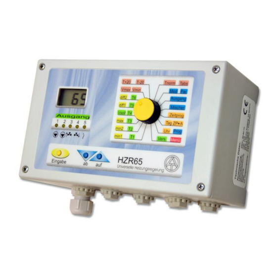
- Page 1 HZR 65 Version P5.6 Universal heating controller Operation Installation instructions...
-
Page 3: Table Of Contents
Contents: Safety requirements ..................4 Maintenance ..................... 4 Generally applicable rules ................5 Diagram 0: Solid fuel boiler, buffer tank, heating circuit, requirement additional heating .. 6 Diagram 16: Automatic boiler, hot water tank, heating circuit, burner requirement ... 8 Diagram 32: Automatic boiler, (combined) buffer, heating circuit, burner requirement ... -
Page 4: Safety Requirements
Safety requirements: All installation and wiring work on the controller must only be carried out in a zero-volts state. The opening, connection and commissioning of the device may only be carried out by competent personnel. In so doing, all local security requirements must be adhered to. -
Page 5: Generally Applicable Rules
Generally applicable rules for the following diagrams: The hydraulic diagrams of this manual are only diagrams in principle. They do not de- scribe or replace a professional system development. There is no guarantee for func- tion if directly copied. When used for floor and/or wall heaters: Here, a safety thermostat must be used just as with conventional heater controllers. -
Page 6: Diagram 0: Solid Fuel Boiler, Buffer Tank, Heating Circuit, Requirement Additional Heating
Diagram 0: Solid fuel boiler, buffer tank, heating circuit, requirement additional heating A5… requirement additional heating Sensors Outputs T1…. Boiler A1…. Heat circuit pump T2…. Tank top A2…. Tank feed pump T3…. Tank bottom A3…. Mixer open T4…. Heating circuit flow A4…. - Page 7 Program 1: Burner requirement A5 refers to sensor T3 A5 = T3 < max Program 2: Separated switch-on and switch-off thresholds for burner requirement. A5 on = T2 < min2 + diff2 A5 off = T2 > max Program 3: as program 2, but switch-off threshold refers to T3 (holding circuit). A5 on = T2 <...
-
Page 8: Diagram 16: Automatic Boiler, Hot Water Tank, Heating Circuit, Burner Requirement
Diagram 16: Automatic boiler, hot water tank, heating circuit, burner requirement A5 = burner requirement Pellets- or fossil fuel boiler Sensors Outputs T1…. Boiler A1…. Heat circuit pump T2…. Tank top A2…. Tank feed pump T3…. Tank bottom A3…. Mixer open T4…. - Page 9 A1 = T1 > min1 & (heating = active) A2 = T1 > min1 & T1 > T2 + diff1 & (T2 < max or (heating = not active)) A5 = (T2 < max & tp(A2)) or ((T1 < min2 or T1 < Vsoll + diff2) & (heating = active)) all programs +1: priority for hot water tank A1 (+1) = A1 only if not ((T2 <...
-
Page 10: Diagram 32: Automatic Boiler, (Combined) Buffer, Heating Circuit, Burner Requirement
Diagram 32: Automatic boiler, (combined) buffer, heating circuit, burner require- ment A5 = burner requirement Pellets- or fossil fuel boiler Sensors Outputs T1…. Boiler A1…. Heating circuit pump T2…. Tank top A2…. Tank feed pump T3…. Tank center A3…. Mixer open T4…. - Page 11 Program 33: Separated switch-on and switch-off thresholds for burner requirement A5 on = T2 < min2 + diff2 A5 off = T2 > max Program 34: as program 33, but switch-off threshold on T3 (holding-circuit). A5 on = T2 < min2 + diff2 A5 off = T3 >...
-
Page 12: Diagram 48: Buffer, Hot Water Tank, Heating Circuit, Burner Requirement
Diagram 48: buffer, hot water tank, heating circuit, burner requirement A5 = burner requirement Sensors Outputs T1…. Buffer top A1…. Heating circuit pump T2…. freely useable A2…. Hot water tank feed pump T3…. Hot water tank bottom A3…. Mixer open T4…. - Page 13 Program 49: as program 48, but switch-off threshold of burner requirement on T2 (holding- circuit) A5 on = T1 < min2 A5 off = T2 > min2 + diff2 Program 50: Burner requirement referring to nominal flow temperature Vsoll and T2 A5 = T2 <...
-
Page 14: Diagram 64: Solid Fuel Boiler, Buffer, Hot Water Tank, Heating Circuit
Diagram 64: Solid fuel boiler, buffer, hot water tank, heating circuit (T5) (T6) (T7) Sensors Outputs T1…. Boiler A1…. Heating circuit pump T2…. Buffer top A2..Hot water tank feed pump A3…. Mixer open T3…. Hot water tank bottom T4…. Heating circuit flow A4…. - Page 15 all programs +1: Feeding the hot water tank refers to the boiler as to the buffer tank temper- ature. A1 off A2 off A2 off A5 off T1 < min1 T2 < min2 or T1 < min1 T1 < min1 and T2 <...
- Page 16 all programs +2: Sensor T6 is not employed as room sensor, but as reference sensor for feeding buffer tank (tank bottom). Note: T6 must be set as standard sensor (Std) (see selector switch position Mod – Par). In position “Par” the use of sensor T6 must be set: rAS ...
-
Page 17: Diagram 80: Solar Power Unit, (Combined) Buffer Tank, Heating Circuit, Burner Requirement
Diagram 80: Solar power unit, (combined) buffer tank, heating circuit, burner requirement A5 = burner requirement Sensors Outputs T1…. Collector A1…. Heating circuit pump T2…. Tank top A2…. Solar pump T3…. Tank bottom A3…. Mixer open T4…. Heating circuit flow A4…. - Page 18 Program 82: Instead of burner requirement (program 80) A5 is a hot water tank feed pump. Sensor T6 is no room sensor, but a tank sensor. Note: T6 must be set as standard sensor (Std) (see selector switch position Mod – Par). In position “Par” the use of sensor T6 must be set: rAS ...
- Page 19 Program 85: A5 is a feed pump between boiler and buffer tank T2; A2 is the feed pump between boiler and hot water tank T3. A1 off A2 off A5 off T2 < min2 T1 < min1 T1 < min1 diff1 diff2 A1 on...
-
Page 20: Diagram 96: Boiler (Or Buffer Tank), Hot Water Tank, 2 Heating Circuits
Diagram 96: Boiler (or buffer tank), hot water tank, 2 heating circuits Sensors Outputs T1…. Boiler A1…. Heating circuit pump 1 T2…. Heating circuit 2 return A2…. Heating circuit pump 2 T3…. Tank bottom A3…. Mixer open T4…. Heating circuit 1 flow A4…. - Page 21 Program 98: Combined buffer tank instead of boiler and hot water tank. Thus output A5 can be used for burner requirement by T1. A5 on = T1 < max A5 off = T1 > max + diff2 Program 100: as program 98, but switch-off threshold of burner requirement at T3 (holding- circuit).
-
Page 22: Diagram 112: Heat Pump Control And Requirement, Heating Circuit Pump, Solar Collector
Diagram 112: Heat pump control and requirement, heating circuit pump, solar collector, hot water tank A5 = Heat pump require- ment Sensors Outputs T1…. Collector A1…. Heating circuit pump T2…. Tank bottom A2…. Solar pump T3…. Tank top A3…. Differential function T4…. -
Page 23: Diagram 128: Buffer Tank, Heating Circuit Via Pre-Mixed District Heating Pipe, Switch-Over Valve Hot Water, Heating Requirement Resp. Feed Pump
Diagram 128: Buffer tank, heating circuit via pre-mixed district heating pipe, switch-over valve hot water, heating requirement resp. feed pump A5 = burner requirement Sensors Outputs T1…. Buffer tank top A1…. Heating circuit pump T2…. Buffer tank bottom A2…. 3-way valve hot water tank T3…. - Page 24 Program 129: As Program 128, but switch-off threshold of burner requirement refers to T2 (holding-circuit). A5 on = T1 < min2 A5 off = T2 < min2 + diff2 Program 130: A5 has feed pump function instead of burner requirement. Sensor T6 is not employed as room sensor, but as tank sensor.
-
Page 25: Burner Requirement
Diagram 144: Automatic boiler, tank, mixer for increasing return, heating circuit pump, burner requirement Burner requirement Sensors Outputs T1…. Automatic boiler A1…. Feed pump T2…. Tank center A2…. Heating circuit pump T3…. Tank bottom A3…. Mixer open T4…. Return line boiler A4…. - Page 26 Program 145: Heating circuit pump is switched mainly by thermostat threshold min2, T5 = outdoor temperature. A2 = T2 > min2 & (heating = active) Program 146: As Program 144, but heating circuit pump is switched by controlled system T2 –...
-
Page 27: Installing Instructions
Installing instructions Installing the sensor(s) Correct arrangement and installation of the sensors is extremely important for correct func- tioning of the system. It should be ascertained that the sensors are completely inserted in the immersion sleeves. The threaded cable connections can serve as strain relief. Fundamentally sensors should not be exposed to moisture (such as condensation) since this can diffuse through the cast resin and damage the sensor. -
Page 28: Installing The Unit
Installing the unit CAUTION! ALWAYS PULL THE MAINS PLUG BEFORE OPENING THE CASE! Unscrew the 4 screws at the edges of the case. The controlling electronic is situated in the cover plate and is connected by a ribbon cable to the mains module, which is set in the basin of the case. -
Page 29: Data Line (Dl)
The data line was specially developed for the UVR series and is only compatible with the products of Technische Alternative. It is only made for generating outputs and is suitable as interface to the PC for transferring the measured temperatures and output states. -
Page 30: Selector Switch
Selector switch The selector switch has 16 different positions. Each position has two functions (e.g. switch position min2 / T2). The value, which is nearer to the selector switch, will be displayed with- out pressing of the yellow key “Eingabe” (e.g. T2). By pressing the yellow key “Eingabe” (= “input”) the second value will be displayed (e.g. - Page 31 Schematic representation of setting values:...
- Page 32 Vsoll Nominal flow temperature, which is calculated based on measured temperatures and heating curve (not changeable check value). In normal cases it must be nearly the same value as temperature T4 (flow senor). Vmin Even if the calculated nominal flow temperature is decreasing this threshold, the controller allows no lower temperature;...
- Page 33 Prog Selection of the program number according to the chosen diagram. The pro- gram number defines the basic function of the controller and is the most important input. Setting by the blue keys ab/auf (down/up); ew = P 0 Vers In this switch position the software version of the computer is displayed (e.g.
-
Page 34: Mod (Operating Mode) - Par (Parameters)
Mod (Operating mode) - Par (Parameters) The different operating modes refer exclusively to mixer control and heating circuit pump. All others outputs are still controlled according to program and setting in all operating modes. That concerns the standby function as well. Automatic mode „Aut”... -
Page 35: Room Sensor Raspt
Room sensor RASPT Operation mode: The room sensor RASPT is a special development of „Technische Alternative” and is provided for installing in living rooms (reference room). It should not be installed near to a heating source or to a window. -
Page 36: Basic Principle Of Heat Curve
Basic principle of heat curve This principle allows automatic temperature control of the heating circuit flow temperature depending on outdoor and room temperature. Description: By setting the values T+20 and T-20 it is possible to set the flow temperature of heating circuit, measured at T4 (flow temperature sensor). -
Page 37: Setting The Time Switch Function
Setting the time switch function As soon a time program is allocated to the heating circuit output A1 this function allows normal heating mode only within the switch- on and switch-off times. I.e. the function switch- es over between normal heating and lowered mode. This function mode acts only on heat circuit with output A1. - Page 38 Time program P1 = time program 1 (setting range: P1 to P5) 1= switching point 1 (1, 3, 5 = on / 2, 4, 6 = off) Short taps on “ab/auf” keys cause switching from P1.1 up to P5.6. Time setting for each switching point 5.0 = switch-on time 05:00 am;...
-
Page 39: Menu
Menu (“Menü”) By means of sub menus („Menü“ in switching position Vers/Menü) the selection of further basic functions for optimizing the heating system is possible. These functions can change the control features radically; therefore the handling with these sub menus should be done only by experts, resp. -
Page 40: Mixer Control Parameter Mr
Mixer control parameter Mr 2 sec Menu – mixer control mode = Outdoor temperature control (factory setting, ex works=ew) 2 sec = Fixed value control Selection of mode = Difference temperature control = Outdoor & room temperature control short = Room temperature control As not all parameters are needed in all modes, only the necessary parameters are displayed. - Page 41 Percentage of room influence r = Percentage of room influence Setting range: 1 to 90 % ex works ew = 50 short Eu = Increase in switch-on power in % Increase of switch-on power based on lowering time of 10 hours Setting range: 0 to 9 % ex works ew: 0 short...
- Page 42 Fir - Fixed value control In normal heating mode the nominal flow temperature is kept at the value set in “T-20” and in lowering mode at the value set in “T+20”. Switch-over occurs is based on time switch function (allocation of time windows to output A1). Atr –...
-
Page 43: Heating Circuit Pump Parameter Hpu
Heating circuit pump parameter HPu These parameters cause switching-off behavior of heating circuit pump, when: nominal room temperature is reached; outdoor temperature increases threshold; calculated nominal flow temperature falls below Vmin; a certain sensor exceeds temperature threshold (excess temperature). Additional mixer behavior while deactivated heating circuit pump can be set. 2 sec 2 sec Switch-off heating circuit pump when nominal room temperature is reached... - Page 44 Switch-off heating pump when nominal flow temperature Vsoll < Vmin Switch-off heating circuit pump when nominal flow temperature Vsoll < Vmin; ew = S - J S - J = Yes (Switch-off active) short S - n = No (pump keeps on running) Allocation of sensor for excess temperature protection function Sensor U, on which excess tempera- ture protection function works.
-
Page 45: Legionella Protection Function Les
Legionella protection function LES For avoiding production of legionellae this protection function can be activated. After lapse of cycle time (tc) tank temperature is heated up to nominal temperature (C) be- ginning from start time (h) (depending to program). 2 sec 2 sec Setting of cycle time tc = cycle time for legionella protection... -
Page 46: Sensor Type Sen
Sensor type Sen Menu Sensor type allows switch-over of sensors between Pt1000 and semi-conductor (KTY) types. Factory setting (ex works) of all sensors is Pt1000 (P). 2 sec 2 sec Selected sensor Setting sensor type (Setting range F1 to F6) P = Pt1000 H = KTY (semi-conductor) ex works = P... -
Page 47: After-Running Time Pnl
After-running time PnL During the start phase, the pumps may repeatedly switch on and off for a long time, espe- cially with solar and heating systems with long hydraulic system lines. This response can be reduced by using a speed control or increasing the pump after-run time. Depending on the selected program each output can be allocated an after-running time, except mixer outputs. -
Page 48: Switching Hystereses Hst
Switching hystereses HSt Switching hysteresis is the difference between switch-on and switch-off temperature. I.e. a thermostat set to 70°C with 10K hysteresis switches off at 70°C and on at 60°C. Hystereses are not constant, but change with measured temperature. Setting range is be- tween1 to 9K per 64°C. -
Page 49: Pump Speed Control Pd1, Pd2
Pump speed control Pd1, Pd2 This menu allows activating and adjustment the outputs A1 and A2 for pump speed con- trol. Decrease of flow, e.g. in a boiler, causes – because of the longer dwell time in it – an in- crease of output temperature. - Page 50 Setting desired temperature C C = constant temperature value Temperature in °C, sensor is kept constant at this temperature ew = 50°C short F = Differential control Differential control “1” = warmer temperature sensor T1 “3” = colder temperature sensor T3 short ew = 0 F13 = Differential control between T1 and T3.
- Page 51 Pr = Proportional part The speed is changed one increment per 0.8K deviation from the nominal value. A high number leads to a more stable system but also to greater devia- tion from the temperature set. Setting range: 0 to 9 = 0 to 0.9K, ew=5 short In = Integral part For 1K of deviation from the nominal...
-
Page 52: Technical Data
Technical Data Power supply: 230V +-10%, 50- 60Hz, Power input: max. 4 VA Fuse: 3.15 a fast acting (device & output) Supply cable: 3x 1mm² H05VV-F conforming to EN 60730-1 Protection class: IP40 Allowed ambient temperature: 0 to 45°C Sensors: Pt1000, accuracy between 0 and 1000°C: +-0.35K Tank sensor BFPT1000: Diameter 6 mm, according to immersion sleeves, incl. -
Page 53: Table Of Settings
Table of settings If the control system fails unexpectedly, all of the settings should be reset for initial configura- tion. In this case, problems are inevitable if all of the setting values are entered in the follow- ing table. If there are questions, this table has to be provided. Only then is a simulation possible to reproduce the error. - Page 54 Legionella protection function LES Sensor type SEn Cycle time tc d Sensor T1 Start time h 17 h h Sensor T2 Nominal temperature C 70 °C °C Sensor T3 Sensor T4 Sensor T5 Sensor T6 Pump after-running time PnL Hystereses HSt Output 1 t1 Hysteresis H1 Output 2 t2...
-
Page 55: Instructions For Troubleshooting
Instructions for troubleshooting In general, all of the settings in the menus and the terminals should be checked if there is an error. The most frequent errors: Check the program number. If an output does not switch – check, if “Aut” is set at position “Ausgang” Check the thresholds for on/off (min/max) and the set differential temperatures (diff). - Page 56 EC- DECLARATION OF CONFORMITY Document- Nr. / Date: TA12009 / 19.11.2012 Company / Manufacturer: Technische Alternative elektronische SteuerungsgerätegesmbH. Address: A- 3872 Amaliendorf, Langestraße 124 This declaration of conformity is issued under the sole responsibility of the manufacturer. Product name: HZR65 Product brand: Technische Alternative GmbH.
- Page 60 Legal notice These assembly and operating instructions are protected by copyright. Use outside the copyright requires the consent of the company Technische Alternative elektronische Steuerungsgerätegesellschaft m. b. H.. This applies in particular to reproductions, translations and electronic media.
Need help?
Do you have a question about the HZR 65 and is the answer not in the manual?
Questions and answers