Technische Alternative UVR610 Installation Instructions Manual
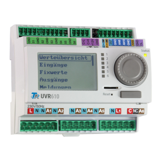
Freely programmable universal controller
Hide thumbs
Also See for UVR610:
- General programming information, user manual (72 pages) ,
- General programming information, user manual (76 pages) ,
- Installation instructions manual (24 pages)

Related Manuals for Technische Alternative UVR610


Summary of Contents for Technische Alternative UVR610
- Page 1 UVR610 FREELY PROGRAMMABLE UNIVERSAL CONTROLLER Installation instructions Manual Version 1.02.1 English...
-
Page 2: Table Of Contents
Technical data UVR610 ........ -
Page 3: Safety Requirements
Safety requirements All installation and wiring work on the controller must only be carried out in a zero volt state. The opening, connection and commissioning of the device may only be carried out by competent personnel. While doing so, they must observe all local safety requirements. This device is state of the art and meets all necessary safety regulations. -
Page 4: Standard Delivery
W x H x D 107 x 95 x 64 mm The lower section can be mounted on a top-hat rail (TS35 support rail to EN 50022 standard). The UVR610 has a width of 6 DU (division units) as per DIN 43880. -
Page 5: Sensor Installation
Sensor installation Correct arrangement and installation of the sensors is extremely important for correct functioning of the system. To this end, also ensure that they are completely inserted in their sensor wells. The cable fittings provided serve as strain relief. When used outdoors, no water must be allowed to penetrate the sensor wells (risk of frost). -
Page 6: Electrical Connection
• Room sensor: This sensor is intended for installation in the living space (reference room). Do not install the room sensor near a heat source or window. By simply replugging a jumper inside the sensor, each room sensor can also be used exclusively as a remote adjuster (no room tempera- ture influence). -
Page 7: Terminal Diagram
Terminal diagram View of the upper enclosure section with terminals Mains: L1... Phase conductor N... Neutral conductor Outputs: C... Root A1 - A6... N/O contact NC... N/C contact A6 N... Neutral conductor Jumper setting J1 and J2 Jumper J2 changes the function of analogue output A7 to a 24 V output for supplying ex- ternal devices. -
Page 8: Sensor Leads
Sensor leads Sensor terminal diagram Sensors are always connected across the relevant sensor terminal (S1 – S6) and sensor earth (GND). In order to prevent measurement fluctuations and ensure perfect signal transmission, sensor leads must not be subject to external negative influences through 230 V cables. Never run sensor leads together with mains voltage cables in the same conduit. -
Page 9: Data Cable For Dl Bus
Take the "Bus load" into consideration as sensors have a relatively high current demand: The UVR610 supplies a total bus load of 100%. The bus loads of the electronic sensors are listed in the technical data of the relevant sensors. -
Page 10: Can Bus Network
CAN Bus network Terminal diagram, CAN bus cable Guidelines for the topology of a CAN network Technical principles The CAN BUS comprises the cables CAN-High, CAN-Low, GND and one +12 V supply cable for BUS components without their own power supply. The combined total load of all devices with 12 V and 24 V supply must not exceed 6 W. -
Page 11: Lightning Protection
In order to protect the individual components of a CAN network against indirect lightning strike, we recommend the use of surge arresters specifically developed for bus systems. Example: CAN bus surge arresters CAN-UES from Technische Alternative Gas discharge arrester for indirect earthing EPCOS N81-A90X... - Page 12 Network (across several buildings) without CAN bus converter CAN-BC2: Max. cable length: 1000 m at 50 kbit/s The screen must be continued at every network node and earthed at a single point, as close to the cable center as possible. We recommend earthing the screen indirectly in the other buildings using a gas discharge arrester.
-
Page 13: Cable Selection And Network Topology
Cable selection and network topology Screened twisted pairs have proven useful in CANopen networks. These are cables with twisted pairs of conductors and a shared external screen. Such cables are relatively resistant to EMC inter- ference and can still carry 50 kbit/s for up to 1000 m. The CANopen recommendations (CiA DR 303- 1) for cable cross-sections are given in the table below. - Page 14 Wiring A CAN BUS network should never have a star topology. Rather, the correct topology is a line from the first device (with terminator) to the second, third and so forth. The last bus device has the termina- tion jumper again. Example: Connection of three network nodes (NWN) with a 2x2-pole cable and termination of the ter- minal network nodes (network inside one building) Each CAN network is to be provided with a 120 ohm BUS terminator at the first and last network sub-...
- Page 15 Changing to cable types with different characteristic impedances is only permitted via signal sepa- ration through a CAN bus converter. However, such networks do not comply with the recommended specification. Technische Alternative RT GmbH therefore cannot guarantee trouble-free operation if one of the three options listed above...
-
Page 16: Outputs
Outputs Terminal diagram, switching outputs For maximum current load of the outputs, see the technical data. Output 6 with voltage applied Output 6 is potential-free at the factory. If it is to be connected to the voltage of the controller, the phase (routed out again next to terminals A6) must be connected to the root. -
Page 17: Terminal Diagram For Analogue Outputs (0-10V / Pwm)
The M-Bus has 2 wires: M-Bus (output 9) and GND (sensor earth). The power supply for reading data from M-Bus devices is provided by the UVR610. Cables can be routed with a star topology or in series (from one device to the next). Ring topology is not permitted. -
Page 18: Connection Auxiliary Relay Hirel-230V
Connection auxiliary relay HIREL-230V Example: Connection to analogue outputs A7 and A8 Program outputs A7 and A8 as switching outputs. The auxiliary relay cannot be integrated in the module; it requires its own enclosure HIREL-230V wiring diagram Both relay outputs are protected by the fuse on the relay module. Terminal "W" therefore corresponds to phase conductor "L". -
Page 19: Technical Data Uvr610
Technical data UVR610 All inputs Temperature sensors type PT1000, KTY (2 kΩ/25 °C), KTY (1 kΩ/ 25 °C), PT100, PT500, Ni1000, Ni1000TK5000 and room sensors RAS or RASPT, radiation sensor GBS01, thermocouple THEL, humidity sensor RFS, rain sensor RES01, pulses max. 10 Hz (e.g. for VSG flow rate transducer), voltage up to 3.3 V DC, resistance (1-100 kΩ),... -
Page 20: Tips On Troubleshooting
Tips on troubleshooting Tech-support We offer our customers free support in the event of questions or issues with our products. Important: in order to answer your questions, we require the device serial number in every case. If you are unable to locate the serial number, help with finding it is available on our homepage: https:/ /www.ta.co.at/en/faq/serial-numbers/ You can submit your request on our homepage using the following link:... - Page 21 If the sensor is faulty, note the sensor type when replacing. While it is possible to use a different type of sensor, the parameters for that input also have to be set to suit the type of sensor used. The current standard type used by Technische Alternative is PT1000. KTY (2 kΩ) was the standard type until 2010/2011.
-
Page 22: Troubleshooting In The Can Network
Power Max. power max. [W] consumption consumption [W] typ. [W] UVR610 max. 8 max. 5 0,80 / 1,55 1,0 / 1,9 Definitions according to Official Journal of the European Union C 207 dated 03/07/2014 The classification applied is based on optimum utilisation and correct application of the products. - Page 23 EU Declaration of conformity Document-No. / Date: TA19003 / 19.06.2019 Company / Manufacturer: Technische Alternative RT GmbH Address: A-3872 Amaliendorf, Langestraße 124 This declaration of conformity is issued under the sole responsibility of the manufacturer. Product name: UVR610 Product brand:...
- Page 24 Note: The following warranty conditions do not in any way limit the legal right to warranty, but rather expand your rights as a consumer. 1. The company Technische Alternative RT GmbH provides a one-year warranty from the date of purchase for all the devices and parts which it sells. Defects must be reported immediately upon detection and within the guarantee period.
Need help?
Do you have a question about the UVR610 and is the answer not in the manual?
Questions and answers