
Subscribe to Our Youtube Channel
Related Manuals for Technische Alternative UVR65


Summary of Contents for Technische Alternative UVR65
- Page 1 UVR65 UNIVERSAL CONTROLLER Version 1.01 Programs Installation Electric Connection User Guide Manual Version 1.01.5 English...
- Page 3 Diese Anleitung ist im Internet auch in anderen Sprachen unter www.ta.co.at verfügbar. This instruction manual is available in English at www.ta.co.at Ce manuel d’instructions est disponible en langue française sur le site Internet www.ta.co.at Questo manuale d’istruzioni è disponibile in italiano sul sito Internet www.ta.co.at Estas instrucciones de funcionamiento están disponibles en español, en Inter- net www.ta.co.at.
-
Page 4: Table Of Contents
Table of contents Safety requirements ............8 Maintenance . - Page 5 Table of contents Building drying – General Information ......... . .60 Basics .
- Page 6 Table of contents Settings ..............102 Technician level .
- Page 7 Table of contents Parameters ............141 Example for threshold values Max/Min/Diff .
-
Page 8: Safety Requirements
Safety requirements All installation and wiring work on the controller must only be carried out in a zero volt state. The opening, connection and commissioning of the device may only be carried out by competent personnel. While doing so, they must observe all local safety requirements. This device is state of the art and meets all necessary safety regulations. -
Page 9: Generally Applicable Rules
Generally applicable rules For the proper use of this device The manufacturer’s warranty does not cover any indirect damage to the unit if the technician install- ing the unit does not equip it with any additional electromagnetic modules (thermostat, possibly in combination with a one-way valve) to protect the device from damage as a result of malfunction un- der the following circumstances: •... -
Page 10: Step By Step" Setup Guide
„Step by Step“ Setup guide The following guide might give you instructions on setting up the device, but it is of utmost importance to read the entirety of the instruction manual – especially the chapters „Pro- grams“ and „Operation“. Level Choose a hydraulic diagram based on the sketches of system dia- grams. -
Page 11: Hydraulic Diagrams
Hydraulic diagrams The hydraulic diagrams displayed in this booklet are practical sketches. They serve to ease the choice of the correct program, but don‘t replace or even describe the planning of your system‘s construction. As such, we can‘t guarantee your system‘s functionality if you imitate this booklet‘s hydraulic diagrams with your construction. -
Page 12: Differential Control - Programs
Differential control – Programs Program 0 – Simple solar system (factory settings) S3 only used in programs +1 necessary settings: max1 ... limit CYL S2 àA1 max2 ... see all programs +1 min1 ... activation temp. coll. S1 àA1 diff1 ... -
Page 13: Program 16 - Cylinder Charge From A Boiler
Program 16 – Cylinder charge from a boiler S3 only for program +1 necessary settings: max1 ... limit CYL S2 àA1 max2 ... see all programs +1 min1 ... activation temp. boiler S1 àA1 diff1 ... boiler S1 - CYL S2 àA1 Program 16: The pump A1 runs, if: •... -
Page 14: Program 48 - Solar Power System With 2 Consumers
Program 48 – Solar power system with 2 consumers necessary settings: max1 ... limit CYL1 S2 à max2 ... limit CYL2 S3 à max3 ... see all programs +2 à min1 ... activation temp. coll. S1 A1, A2 min2 ... see all programs +4 diff1 ... -
Page 15: Program 64 - Solar Power System With 2 Solar Panels
Program 64 – Solar power system with 2 solar panels necessary settings: max1 ... limit CYL S3 àA1, A2 max2 ... see all programs +2 min1 ... activation temp. coll. 1 S1 àA1 min2 ... activation temp. coll. 2 S2 àA2 diff1 ... -
Page 16: Program 80 - Simple Solar System And Cylinder Charge From A Boiler
Program 80 – Simple solar system and cylinder charge from a boiler necessary settings: max1 ... limit CYL S2 à max2 ... limit CYL S4 à max3 ... see all programs +4 à min1 ... activation temp. coll. S1 à min2 ... -
Page 17: Program 96 - Buffer And Hot Water Cylinder Charging Via Solid Fuel Boiler
The charging pump A2 runs, if: • S3 exceeds the threshold min2 • and S3 is greater than S2 by the difference diff2 • and S2 has not exceeded the threshold max2. A1 = S1 > (S2 + diff1) & S1 > min1 & S2 < max1 A2 = S3 >... -
Page 18: Program 112 - 2 Independent Differential Circuits
All programs +1: Additionally, the charging pump A2 is also regulated via the heater boiler temperature S1. Pump A2 runs, if: • S1 exceeds the threshold min1 • and S1 is greater than S4 by the difference diff3 • and S4 has not exceeded max2 •... -
Page 19: Program 128 - Burner Request And Solar System (Or Charging Pump)
Program 128 – Burner request and solar system (or charging pump) necessary settings: max1 ... limit CYL S2 à A1 max3 ... burner req. off CYL S3 à A3 min1 ... activation temp. coll. S1 à A1 min2 ... see all programs +2 min3 ... -
Page 20: Program 144 - Solar System With Layered Cylinder Charging
Program 144 – Solar system with layered cylinder charging Layered systems are only practical if the speed control is activated (Absolute value control system: Mode „Normal“ and sensor input S1) necessary settings max1 ... limit CYL S2 à A1 max2 ... -
Page 21: Program 160 - Insertion Of Two Boilers Into A Heating System
Program 160 – Insertion of two boilers into a heating system necessary settings max1 ... limit CYL S2 à A1 max2 ... limit CYL S3 à A2 max3 ... burner req. off CYL S3 à A3 min1 ... activation temp. boiler S1 à... -
Page 22: Program 176 - Solar System With 2 Consumers And Charging Pump Functionality
Program 176 – Solar system with 2 consumers and charging pump functionality necessary settings: max1 ... limit CYL1 S2 à A1 max2 ... limit CYL2 S3 à A2 max3 ... limit CYL1 S4 à A3 min1 ... activation temp. coll. S1 à... -
Page 23: Program 192 - Solar System With 2 Consumers And Charging Pump (Heating Boiler)
All programs +8: The limitation of cylinder CYL1 is regulated via the independent sensor S6 and the threshold max1 (no maximum threshold S2!). The Priority Ranking between CYL1 and CYL2 is parameterized in the menu Settings/Tech- nician level/Parameters/Priority ranking. Additionally, a solar priority function can be set up in the menu Settings/Expert level/Solar priority (more information in the chapter „Solar Pri- ority“). -
Page 24: Program 208 - Solar System With 2 Consumers And Burner Request
All programs +2: If both cylinders have reached their maximum temperatures due to the so- lar system, pump A3 is activated (re-cooling function). All programs +4: Both solar circuits have separate activation thresholds at S1: Output A1 retains min1 and A2 regulates via min3. The Priority Ranking between CYL1 and CYL2 can be parameterized in the menu Settings/ Technician level/Parameters/Priority ranking. -
Page 25: Program 224 - Solar System With 3 Consumers
All programs +2: The burner request (A3) is only regulated via sensor S5. A3 (on) = S5 < min3 A3 (off) = S5 > max3 (dominant) All programs +4: Both solar circuits have separate activation thresholds at S1: Output A1 retains min1 and A2 is regulated via min2. All programs +8: If at least one of the two solar circuits is active, the burner request is blocked. - Page 26 Program 224: Pump A1 runs, if: • S1 exceeds the threshold min1 • and S1 is greater than S2 by the difference diff1 • and S2 has not exceeded the threshold max1. Pump A2 runs, if: • S1 exceeds the threshold min1 • and S1 is greater than S3 by the difference diff2 •...
-
Page 27: Program 240 - Solar System With 2 Solar Panels And 2 Consumers
Program 240 – Solar system with 2 solar panels and 2 consumers A1, A2 ... pumps ... switch-over valve (A3/S receives voltage when charging CYL2) necessary settings: max1 ... limit CYL1 S3 à A1, A2 max2 ... limit CYL2 S4 à... -
Page 28: Program 256 - Solar Power System With Two Solar Panels (1 Pump, 2 Stop Valves)
All programs +1: If the difference between the solar panel sensors S1 and S2 exceeds the difference diff3, the colder panel‘s circuit will be deactivated. This prevents heat from being lost on the colder panel when temperatures are mixed. WARNING: In this program, the priority settings do not refer to the pumps, but rather their respective cylinders. -
Page 29: Program 272 - Solar System With 2 Collector Panels And Charging Pump Function
Program 272 – Solar system with 2 collector panels and charging pump function necessary settings: max1 ... limit CYL1 S3 à A1, A2 max2 ... limit CYL2 S4 à A3 min1 ... activation temp. coll. 1 S1 à A1 min2 ... -
Page 30: Program 288 - Solar System With 2 Collector Panels And Burner Request
Program 288 – Solar system with 2 collector panels and burner request necessary settings: max1 ... limit CYL S3 à A1, A2 max3 ... burner req. off CYL S4 à A3 min1 ... activation temp. coll.1 S1 à A1 min2 ... -
Page 31: Program 304 - Solar System With 2 Collector Panels + Charging Pump (Boiler)
Program 304 – Solar system with 2 collector panels + charging pump (boiler) necessary settings: max1 ... limit CYL S3 à A1, A2 max2 ... limit CYL S3 à A3 min1 ... activation temp. coll.1 S1 à A1 min2 ... activation temp. coll.2 S2 à... -
Page 32: Program 320 - Layered Cylinder And Charging Pump
Program 320 – Layered cylinder and charging pump Only practical with speed control activated! (Absolute value control: mode „Normal“ and sensor input S1) necessary settings: max1 ... limit CYL S2 à A1 max2 ... limit CYL S4 à A2 max3 ... -
Page 33: Program 336 - Solar System With 2 Consumers And Layered Cylinder Charging
Program 336 – Solar system with 2 consumers and layered cylinder charging Layered system only practical with speed control activated! (Absolute value control: mode „Normal“ and sensor input S1) necessary settings: max1 ... limit CYL1 S2 à A1 max2 ... limit CYL2 S3 à... -
Page 34: Program 352 - Layered Cylinder And Burner Request
Program 352 – Layered cylinder and burner request Layered system only practical with speed control activated! (Absolute value control: mode „Normal“ and sensor input S1) necessary settings: max1 ... limit CYL S2 à A1 max2 ... limit CYL S4 à A2 max3 ... -
Page 35: Program 368 - Layered Cylinder And Charging Pump
Program 368 – Layered cylinder and charging pump Layered system only practical with speed control activated! (Absolute value control: mode „Normal“ and sensor input S1) necessary settings: max1 ... limit CYL1 S2 à A1 max2 ... limit CYL1 S4 à A2 max3 ... -
Page 36: Program 384 - Layered Cylinder With Bypass Functionality
Program 384 – Layered cylinder with bypass functionality Layered system only practical with speed control activated! (Absolute value control: mode „Normal“ and sensor input S1) necessary settings: max1 ... limit CYL S2 à A1 max2 ... limit CYL S4 à A2 min1 ... -
Page 37: Program 400 - Solar System With 1 Consumer And 2 Charging Pump Functions
Program 400 – Solar system with 1 consumer and 2 charging pump functions necessary settings: max1 ... limit CYL1 S2 à A1 max2 ... limit CYL2 S4 à A2 max3 ... limit CYL3 S5 à A3 min1 ... activation temp. coll. S1 à... -
Page 38: Program 416 - 1 Consumer, 2 Charging Pumps And Burner Request
Program 416 – 1 consumer, 2 charging pumps and burner request Priority allocation between SP1 and SP2 possible necessary settings: max1 ... limit CYL1 S1 à A1 max2 ... limit CYL2 S2 à A2 max3 ... burner req. off CYL3 S3 à... -
Page 39: Program 432 - Solar System, Burner Request, And One Charging Pump
Pump A1 runs, if: • S4 exceeds the threshold min1 • and S4 is greater than S1 by the difference diff1 • and S1 has not exceeded the threshold max1. • S5 exceeds the threshold min2 • and S5 is greater than S1 by the difference diff3 •... - Page 40 Program 432: Pump A1 runs, if: • S1 exceeds the threshold min1 • and S1 is greater than S2 by the difference diff1 • and S2 has not exceeded the threshold max1. The charging pump A2 runs, if: • S3 exceeds the threshold min2 • and S3 is greater than S4 by the difference diff2 •...
-
Page 41: Program 448 - Burner Request And 2 Charging Pumps
Program 448 – Burner request and 2 charging pumps necessary settings: max1 ... limit CYL1 S2 à A1 max2 ... limit CYL2 S3 à A2 max3 ... burner req. off CYL1 S4 à A3 min1 ... activation temp. boiler S1 à... - Page 42 All programs +1: necessary settings: max1 ... limit CYL1 S4 à A1 max2 ... limit CYL2 S3 à A2 max3 ... burner req. off CYL1 S4 à A3 min1 ... activation temp. boiler S1 à A1 min2 ... activation temp. CYL1 S5 à...
-
Page 43: Program 464 - Solar System With 2 Consumers And Bypass Function
Program 464 – Solar system with 2 consumers and bypass function necessary settings: max1 ... limit CYL1 S2 à A1, A2 max2 ... limit CYL2 S3 à A1, A3 min1 ... activation temp. coll. S1 à A1 min2 ... activation temp. solar flow S4 à... -
Page 44: Program 480 - 2 Consumers And 3 Charging Pump Functions
All programs +4: The two secondary pumps A2 and A3 are only permitted to run if the pri- mary pump A1 runs in automatic mode. The Priority Ranking between CYL1 and CYL2 can be set in the menu Settings/Technician level/Parameters/Priority ranking. Additionally, a solar priority function can be set up in the menu Settings/Expert level/Solar priority (see „Solar Priority“... - Page 45 All programs +1: necessary settings: max1 ... limit CYL1 S2 à A1 max2 ... limit CYL1 S2 à A2 max3 ... limit CYL2 S4 à A3 min1 ... activation temp. heat source S1 à A1, A3 min2 ... activation temp. boiler S3 à...
-
Page 46: Program 496 - 1 Consumer And 3 Charging Pump Functions
Program 496 – 1 Consumer and 3 charging pump functions necessary settings: max1 ... limit CYL S2 à A1 max2 ... limit CYL S2 à A2 max3 ... limit CYL S2 à A3 min1 ... activation temp. coll. S1 à A1 min2 ... -
Page 47: Program 512 - 3 Independent Differential Circuits
Program 512 – 3 independent differential circuits necessary settings: max1 ... limit CYL1 S2 à A1 max2 ... limit CYL2 S4 à A2 max3 ... limit CYL3 S6 à A3 min1 ... activation temp. coll. 1 S1 à A1 min2 ... -
Page 48: Program 528 - 2 Independent Differential Circuits & Independent Burner Request
Program 528 – 2 independent differential circuits & independent burner request necessary settings: max1 ... limit CYL1 S2 à A1 max2 ... limit CYL2 S4 à A2 max3 ... burner req. off CYL3 S5 à A3 min1 ... activation temp. coll.1 S1 à... -
Page 49: Program 544 - Cascade: S1 -> S2 -> S3 -> S4
Program 544 – Cascade: S1 -> S2 -> S3 -> S4 necessary settings: max1 ... limit CYL1 S2 à A1 max2 ... limit CYL2 S3 à A2 max3 ... limit CYL3 S4 à A3 min1 ... activation temp. coll. S1 à... -
Page 50: Program 560 - Cascade: S1 -> S2 / S3 -> S4 -> S5
Program 560 – Cascade: S1 -> S2 / S3 -> S4 -> S5 necessary settings: max1 ... limit CYL1 S2 à A1 max2 ... limit CYL2 S4 à A2 max3 ... limit CYL3 S5 à A3 min1 ... activation temp. coll. S1 à... -
Page 51: Program 576 - Cascade: S4 -> S1 -> S2 + Burner Request
Program 576 – Cascade: S4 -> S1 -> S2 + burner request necessary settings: max1 ... limit CYL3 S2 à A1 max2 ... limit CYL2 S1 à A2 max3 ... burner req. off CYL1 S3 à A3 min1 ... activation temp. CYL2 S1 à... -
Page 52: Program 592 - 2 Generators For Two Consumers + Independent Differential Circuit
Program 592 – 2 generators for two consumers + independent differential circuit No diagram available necessary settings: max1 ... limit CYL1 S3 à A1 max2 ... limit CYL2 S4 à A2 max3 ... limit CYL3 S6 à A3 min1 ... activation temp. boiler 1 S1 à... - Page 53 Program 593: necessary settings: max1 ... limit CYL1 S3 à A1, A2 max2 ... limit CYL2 S4 à A1, A2 max3 ... limit CYL3 S6 à A3 min1 ... activation temp. boiler 1 S1 à A1 min2 ... activation temp. boiler 2 S2 à...
-
Page 54: Program 608 - 2 Generators For 2 Consumers + Burner Request
Program 608 – 2 generators for 2 consumers + burner request No diagram available necessary settings: max1 ... limit CYL1 S3 à A1 max2 ... limit CYL2 S4 à A2 max3 ... burner req. off S5 à A3 min1 ... activ. temp. boiler 1 S1 à... - Page 55 All programs +8: necessary settings: max1 ... limit CYL1 S3 à A1, A2 max2 ... limit CYL2 S4 à A1, A2 max3 ... burner req. off S5 à A3 min1 ... activ. temp. boiler 1 S1 à A1 min2 ... activ. temp. boiler 2 S2 à...
-
Page 56: Program 624 - Solar System With One Consumer And Swimming Pool
Program 624 – Solar system with one consumer and swimming pool necessary settings: max1 ... limit CYL1 S2 à A1 max2 ... limit CYL2 S3 à A2 max3 ... see all programs +2 min1 ... activation temp. coll. S1 à A1, A2 min2 ... -
Page 57: Program 640 - Dhw Preparation Incl. Circulation
Program 640 – DHW preparation incl. circulation Only practical with speed control activated! Absolute value control: mode „Inverted“ input S5, Differential v.c. mode „Normal“ sensors S3 and S5) WARNING: The excess collector temperature limiter is activated for A1 by default. This must be changed to A3 or deactivated entirely. -
Page 58: Program 656 - Dhw Preparation Incl. Circulation + Burner Request
Program 656 – DHW preparation incl. circulation + burner request Only practical with speed control activated! Absolute value control: mode „Inverted“ input S1, Differential v.c. mode „Normal“ sensors S3 and S1 necessary settings: max1 ... limit circulation return S4 à A2 max2 ... -
Page 59: Program 672 - 3 Generators For 1 Consumer + Differential Circuit + Burner Request
Program 672 – 3 generators for 1 consumer + differential circuit + burner request No diagram available necessary settings: max1 ... limit CYL1 S2 à A1 max2 ... limit CYL2 S5 à A2 max3 ... burner req. off CYL2 S5 à... -
Page 60: Building Drying - General Information
Building drying – General Information A special application of the universal controller UVR65 is the energy-saving and cost-effective drying of basements and other building parts via regulation of ventilation. The special functionality of the sensor RFS-DL (measurement of absolute humidity) enables the comparison of the values for abso- lute humidity indoors and outdoors to turn a fan on or off. -
Page 61: Programs - Building Drying
Choosing a building drying program automatically binds inputs and external sensors according to the table below to reduce the amount of necessary manual setup. These settings can of course be changed, if so desired. Input Ext. Sensor Value Absolute humidity indoors Absolute humidity outdoors Temp. -
Page 62: Program 690 - Room Drying, Minimum Temperature Monitoring, Comfort Ventilation
Program 690 – Room drying, minimum temperature monitoring, comfort ventilation A room‘s humidity is to be reduced. If it becomes too cold in the ventilated room, the fan is deacti- vated. In order to guarantee a certain degree of air quality, the fan is activated despite exterior humidity or if the room temperature falls below a set minimum. -
Page 63: Program 692 - Room Drying, Room Temp. Monitoring, Comfort Ventilation, For Wine Cellars
Program 692 – Room drying, room temp. monitoring, comfort ventilation, for wine cellars A wine cellar‘s humidity is to be lowered. To ensure a certain level of air quality, the fan is activated despite exterior humidity. The fan is activated via one or more time windows, preferably in the cool morning hours. -
Page 64: Heating Circuit Control - Programs
Heating circuit control - Programs All heating circuit programs (except program groups 816 and 976 as well as other stated exceptions) require the following settings: Overview Technician level: Time/Date Menu Parameters Mode (preferably Auto) Basic parameters Time programs Heat curve Expert level: Set flow temp. - Page 65 Program 800: Activation of heating circuit pump A1, if sensor S4 has exceeded the thresh- old min1. If sensor S4 is not in use, then the corresponding program setting must be adjust- ed accordingly. All programs +1: Like program 800, but the heating circuit pump A1 is also enabled via sen- sor S5 and the minimum threshold min2 (2 generators for the heating circuit).
-
Page 66: Program 816 - Boiler Circuit Pump, Mixer For Return Flow Boosting
Program 816 – Boiler circuit pump, mixer for return flow boosting Program 816: Boiler circuit pump A1 is enabled, if S1 exceeds the threshold min1 and S4 is greater than S2 by the difference diff1 and S2 has not exceeded the threshold max1. A1 = S1 >... -
Page 67: Program 832 - Solid Fuel Burner, Buffer Cylinder, Heating Circuit, Additional Heating Req
Program 832 – Solid fuel burner, buffer cylinder, heating circuit, additional heating req. S1 ... Room sensor A1 ... Heating circuit pump S2 ... Temperature outdoors A2 ... Buffer charging pump S3 ... Heating circuit flow A3 ... Heating request S4 ... - Page 68 Program 833: The burner is regulated only via S5. A3 on = S5 < min3 A3 off = S5 > max3 Program 834: Separate activation and deactivation thresholds via sensors S5 and S6. A3 on = S6 < min3 A3 off = S5 > max3 Program 835: Activation and deactivation thresholds are related to the set flow tempera- ture.
-
Page 69: Program 896 - Automatic Burner, Cylinder, Heating Circuit, Boiler Request
Program 896 – Automatic burner, cylinder, heating circuit, boiler request Sensors Outputs S1 ... Room sensor A1 ... Heating circuit pump S2 ... Temperature outdoors A2 ... Cylinder charging pump S3 ... Heating circuit flow A3 ... Boiler request S4 ... Boiler A4 ... - Page 70 Program 896: A1 = S4 > min1 & Heating = active A2 = S4 > min1 & S4 > S6 + diff1 & S6 < max1 A3 = (S6àmin3/max3 & TP ) or ((S4 < min2 or S4 < Set flow temp + diff2) & Req.
-
Page 71: Program 912 - Automatic Boiler, (Combined) Buffer, Heating Circuit, Burner Request
Program 912 – Automatic boiler, (combined) buffer, heating circuit, burner request Sensors Outputs S1 ... Room sensor A1 ... Heating circuit pump S2 ... Temperature outside A2 ... Buffer charging pump S3 ... Heating circuit flow A3 ... Burner request S4 ... - Page 72 Program 913: Separate deactivation threshold for the burner request at S5 and S6 (hold cir- cuit). A3 on = S6 < min3 & S4 < max2 & TP & TP Req. DHW Req. burner A3 off = S5 > max3 or S4 > max2 Program 914: Hold circuit with difference to the set flow temperature.
-
Page 73: Program 928 - Buffer, Cylinder, Heating Circuit, Boiler Request
Program 928 – Buffer, Cylinder, Heating circuit, boiler request Sensors Outputs S1 ... Room sensor A1 ... Heating circuit pump S2 ... Temperature outdoors A2 ... Cylinder charging pump S3 ... Heating circuit flow A3 ... Heating request S4 ... Cylinder bottom A4 ... - Page 74 Program 929: Like program 928, deactivation threshold of the burner request at S5 (holding circuit). A2 = S6 > min1 & S6 > S4 + diff1 & S4 < max1 & ZP Req. DHW A3 on = S6 < min3 A3 off, = S5 >...
- Page 75 All programs +8: Second energy source next to the buffer with sensor S5. All conditions at S6 also count for S5. The higher temperature comes into effect. However all conditions only at S5 remain unchanged. Example: program 936 (= 928 + 8) A1 = (S6 >...
-
Page 76: Program 944 - Solid Fuel Boiler, Buffer, Cylinder, Heating Circuit
Program 944 – Solid fuel boiler, buffer, cylinder, heating circuit Sensors Outputs S1 ... Cylinder bottom A1 ... Heating circuit pump S2 ... Temperature outdoors A2 ... Cylinder charging pump S3 ... Heating circuit flow A3 ... Buffer charging pump S4 ... - Page 77 All programs +1: The cylinder is charged in regard to both the boiler‘s and the buffer‘s tem- perature. A2 = (S4 > min1 & S4 > S1 + diff2) or (S6 > min2 & S6 > S1 + diff2) & S1 < max2 &...
-
Page 78: Program 960 - Boiler (Or Buffer), Cylinder, 1 Regulated & 1 Unregulated Heating Circuit
Program 960 – Boiler (or buffer), cylinder, 1 regulated & 1 unregulated heating circuit Sensors Outputs S1 ... Room sensor A1 ... Heating circuit pump 1 S2 ... Temperature outdoors A2 ... Heating circuit pump 2 S3 ... Flow heating circuit 1 A3 ... -
Page 79: Programs 976/977/978 - Screed Drying
Program 962: Combined buffer instead of the boiler and the cylinder. As such, output A3 is used for the heating demand via S4. A3 on = S4 < min3 A3 off = S4 > max3 Program 964: Like program 962, but with the deactivation threshold of the heating request at S6 in the buffer (hold circuit) A3 on = S4 <... -
Page 80: Installation Instructions
Installation instructions Sensor installation Correct arrangement and installation of the sensors is extremely important for correct func- tioning of the system. To this end, also ensure that they are completely inserted in their sen- sor wells. The cable fittings provided serve as strain relief. When used outdoors, no water must be allowed to penetrate the sensor wells (risk of frost). - Page 81 • DHW sensor: A rapid reaction to changes in the water volume is extremely important when using the controller in systems that generate domestic hot water by means of an external heat exchanger and variable speed pump (freshwater module). Therefore fit the DHW sensor directly on the heat exchanger outlet.
-
Page 82: Device Installation
Device installation CAUTION! Always disconnect the mains plug before opening the casing! Only work inside the controller with the power cable disconnected. Unscrew the screws on the front and lift the cover. The electronics are located in the cover. The connection to the terminals in the lower section of the enclosure is made by contact pins when the cover is put in place. -
Page 83: Electrical Connection
Measurement drawing of casing (in mm) Electrical connection Caution: This must only be carried out by a qualified electrician in accordance with the rele- vant local regulations. The sensor lines may not be fed through the same cable channel as the supply voltage. - Page 84 CAN-Bus The CAN-Bus serves the purpose of accessing the UVR65 controller from other devices (and vice-versa) and for C.M.I. data logging. The basics of CAN-Bus connections are...
- Page 85 Terminal diagram View of the lower casing section with terminals: Mains: L... Phase conductor N... Neutral conductor PE... Earth conductor Outputs: C... Root (A3) A1 & A2... NO contact NC... N/C contact N... Neutral conductor Mains connection Power is supplied through a power supply unit integrated into the device. The mains connection must therefore be 230 V 50 Hz.
- Page 86 Sensor leads Sensor terminal diagram Sensors are always connected across the relevant sensor terminal (S1 – S6) and sensor earth (GND). There is an earth strip in the base. A connection to the GND terminal must be laid using this strip be- fore the sensors are connected.
-
Page 87: Outputs
Outputs Terminal diagram, switching outputs The maximum current load of the outputs is noted in the chapter Technical data. Terminal diagram for analogue outputs (0-10V / PWM) The connections A4 & A5 are the positive pole, the GND connection is the negative pole. -
Page 88: Mixer Connection
Mixer connection When using a three-point mixer, a connection between the root C and the phase conductor L must be established. This connection plan only applies to program groups 800 and 816. Output A3 serves to close, Output A2 serves to open the mixer. Mains: L... - Page 89 Connection auxiliary relay HIREL-22 Connection of a three-way mixer to the analogue outputs A4 and A5 The auxiliary relay is not to be mounted in the device itself, as it has its own casing. This connection plan only applies to program groups 832 and above.
-
Page 90: Data Line For Dl-Bus
Take the „BUS load“ into consideration as sensors have a relatively high current demand: The controller UVR65 supplies a maximum bus load of 100%. The bus loads of the electronic sensors are listed in the technical data of the relevant sensors. -
Page 91: Can-Bus Network
CAN-Bus network Terminal CAN-Bus line Guidelines for the topology of a CAN network Technical principles The CAN BUS comprises the cables CAN-High, CAN-Low, GND and one +12 V supply cable for bus components without their own power sup- ply. The combined total load of all devices with 12 V and 24 V supply must not exceed 6 W. - Page 92 Gas discharge arrester for indirect earthing EPCOS N81-A90X Examples of different network variants Key to symbols: ... device with its own power supply (RSM610, UVR16x2, UVR1611, UVR65) ... device is supplied by the CAN-Bus (CAN-I/O 45, CAN-MTx2, ...) ... terminated (end devices) ...
- Page 93 Bus rate In the CAN BUS / CAN settings menu of the UVR65, the BUS rate can be set to between 5 and 500 kbit/s, whereby lower BUS rates enable longer cable networks.. However in this case, the cable cross- section must be increased accordingly.
- Page 94 Wiring A CAN BUS network should never have a star topology. Rather, the correct topology is a line from the first device (with terminator) to the second, third and so forth. The last bus device has the termina- tion jumper again. Example: Connection of three network nodes (NWN) with a 2x2-pole cable and termination of the ter- minal network nodes (network inside one building) Each CAN network is to be provided with a 120 ohm BUS terminator at the first and last network sub-...
-
Page 95: Can-Bus - Output Values
CAN-Bus – Output values The controller sends the same set of data to the CAN-Bus, in the form of analogue and digital values. If a value can‘t be sent (for example: value of an external sensor that isn‘t connected) the output will read zero. -
Page 96: Operation - Basics
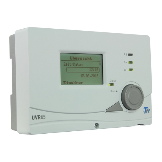
Operation – Basics Device overview The display on the front shows information about sensor measurements, menu position, parameters and such. The bar on the right side of the display moves along with the vertical position in the cur- rently opened menu (= scroll bar). The wheel to the right of the menu serves to navigate through menus. -
Page 97: Example Of Menu View
Example of menu view 1 Title of the current menu 2 Sub-title (not selectable) 3 Scroll bar (indicates vertical menu position) 4 Selected menu point (framed) Pushing down the wheel („Enter“) opens the following window to input/adjust values: 1 Chosen parameter 2 Range of adjustment 3 Chosen value (framed) 4 Confirm/cancel changes... -
Page 98: Operation - General
Operation – General Note: The abbreviation „FS“ as in „Factory settings“ is used frequently. Display (under Settings) Display Timeout Time after which the display‘s background lighting turns off if the device is idle. (FS = 30 seconds) Contrast Screen contrast in percent. (FS = 50.0%) Data admin (under Settings) Function data Load function data from the SD card... -
Page 99: User
User The 3 different user levels have different kinds of rights to access and modify data. User level Rights User Overview: Change time and date No password View: Inputs, control outputs, system status, chosen pro- gram, Adjust: Time programs Settings: Data admin: Load and save function data, view current func- tion data, load Firmware, view system status Display: All settings... -
Page 100: Operation - Differential Control
Operation – Differential control Main Menu This instruction manual shows menus with expert level access. Overview • Time/Date • Inputs • Status control output • System status • Chosen program Settings • Technician level (e.g. parameter menu) • Expert level (basic system settings) •... -
Page 101: Overview
Overview Time/Date Change time and date Inputs* Measurements of the sensors Unused inputs can be set to „unused“ under the menu Settings/ Expert level/Sensor menu which will hide them from this over- view. If no sensor is connected but the input is not set to unused, an error value of 9999,9°C will be displayed (= interruption). -
Page 102: System Status
System status Select the menu point for further information. The example shows no messages or errors being present. Possible displays: „Ok“ (Fct. control), Error. Possible errors: Excess temp. shutdown, Drainback error, Pas- teurization. With function control activated: Lead break, short cir- cuit, circulation error. -
Page 103: Technician Level
Technician level Parameters Adjusting activation, deactivation and difference thresholds (min/max/diff), Priority ranking (only programs with priorities) Time program Setting up 5 time programs with 3 time windows each Timer Setting up a timer function Time/date Time, date, summer time, automatic time change Manual mode Set outputs to Automatic/Manual ON/Manual OFF Datalogging Settings... -
Page 104: Example For Thresholds
Example for thresholds Program 0 is used for this example. MAX1 S2 YES/NO Activate/deactivate the influence of this threshold MAX1 S2 OFF Sensor S2 exceeding this temperature deactivates the output. MAX1 S2 ON The output deactivated by exceeding MAX1 OFF is reactivated below this temperature. -
Page 105: Schematic Representation Of Thresholds
Schematic representation of thresholds... -
Page 106: Time Program
Time program Up to 5 time programs with 3 time windows each can be set up. Choice of time program 1-5 Days of the week for which the time window should activate. Time of day of the window And/Or: Linking between time window and program 1-5: Assigned outputs Two identical time windows follow. -
Page 107: Time/Date
Time/date Time of day Date Automatic time change of Summertime Summertime Yes/No (Only changeable, if automatic time change = No– else this point only indicates the status of the summertime) Manual mode Changing of the individual outputs‘ mode of operation. Choice between Manual/ON (Output constantly on), Manual/OFF (Output constantly off) and Auto (Output regulated according to usual automatic operation and time windows). -
Page 108: Expert Level
Expert level Programming settings to change basic operation Sensor menu: type, designation, correctional values etc. Ext. sensors to read sensors and values via CAN-Bus/DL-Bus Outputs: Designation, status, meter values, run-on time, blocking time and blocking protection Control outputs: Function, mode etc. System protection e.g. -
Page 109: Sensor Menu
Sensor input not in use. KTY (2kΩ) Usage as KTY type sensor. PT1000 ( = FS) Usage as PT1000 type sensor (standard type of the Technische Alternative company). Usage as room sensor RASKTY RASPT Usage as room sensor RASPT Usage as insolation sensor GBS Fixed value Assign a fixed temperature value to the input. -
Page 110: Simulation
Due to the relatively high power drain of external sensors, pay attention to the bus load: The controller UVR65 supplies a maximum bus load of 100%. The electronic sensor FTS-50DL, for example, has a bus load of 25% – a maximum of 4 such sensors can be con- nected to the DL-Bus. -
Page 111: Setting Up External Sensors
Setting up external sensors DL-Bus sensor Designation Each sensor can be given its own designation here. This designa- tion only serves the purpose of identification and has no influence on operation. Source The source from which the signal is being read out. In this case, „DL input“... -
Page 112: Outputs
Outputs In this menu, each used output has its own sub menu, in which each can be given a designation that has no influence on opera- tion. Below that, settings for run-on time and blocking time can be found (further details below). Additionally, several infos and sta- tistics are displayed, such as Mode (Auto/Manual), and meter readings for running hours and impulses („total“, „today“... -
Page 113: Run-On Time
Run-on time Especially solar and heating pumps with long hydraulic pipelines may have issues with con- stant turning on and off again over longer times when attempting to start up. This is espe- cially disadvantageous for modern high-efficiency pumps. Such behavior can be avoided by specific usage of the speed control or by setting up a run-on time. -
Page 114: Control Output
Control output The two control outputs (A4 and A5) are identical in terms of parameterization. The parameters concerning the control outputs are found in this menu. As analogue output, 0-10 V can be generated in 0.1 V steps. In the mode PWM, a digital signal with a frequency of 1 kHz (level approx. 10V) and a variable duty cycle of 0 to 100% is generated. -
Page 115: Absolute Value Control
This example will be used to describe the different possibilities for speed control. Absolute value control = maintaining a sensor‘s value S1 can be kept at a certain temperature (such as 50°C) very well by using the speed control. If the insolation sinks, S1 becomes colder. The control unit then lowers the speed and hence the flow rate. -
Page 116: Differential Control
Differential control = to keep the temperature between two sensors constant Keeping the temperature difference between two sensors, e.g. S1 and S2, allow for a „mod- ulating“ operation of the collector. If S1 drops due to sinking insolation, the difference be- tween S1 and S2 sinks as well. -
Page 117: Event Control
Event control If a set temperature threshold (set value event) is exceeded at the activation sensor, the event control starts, keeping the temperature at the control sensor constant (controller set value). If S3, as exemplified, reaches 60°C (activation threshold), the collector is to be held at a con- stant temperature. -
Page 118: Stability Problems
Stability problems The speed control contains a „PID controller“. It ensures an exact and fast adjustment of the actual value to the set value. In applications such as solar systems and charging pumps, the factory settings likely regulate in a stable manner. Especially the DHW preparation via external heat exchangers (fresh water station) adjusting these values to the specific circum- stances is absolutely necessary. -
Page 119: Output Mode, Correcting Variables
Output mode, Correcting variables Depending on the make of the pump, the control mode of the pump can be set to normal (0-100 „solar mode“, PWM 2) or inverse (100- 0 „heating mode“, PWM 1). There may also be specific require- ments for the limits of the control range. -
Page 120: System Protection
System protection There are two functions for excess collector temperature limitation, two for frost protection, and a cooling function. Except for the first excess temperature limitation, all of these func- tions are deactivated in the factory settings. Excess temp. limiter Steam might build up in an idle system, making a reactivation difficult, as the pump can‘t lift the fluid above the highest point in the system (the collector feed line). -
Page 121: Frost Protection
Frost protection This function is deactivated in the factory settings and only necessary for solar systems that have no frost protection of their own. Souther latitudes offer the possibility of bridging the gap of the few hours below a collector minimum temperature with power from the solar sys- tem‘s cylinder. -
Page 122: Collector Cooling Function
Collector cooling function Using this function, a solar system‘s cylinder can be cooled overnight to allow it to take in warmth again the next day. If the chosen sensor (cylinder temperature) exceeds the specified temperature, the speci- fied outputs will be activated within the specified time window until the temperature is un- derrun again. -
Page 123: Start Function
Start function (ideal for tube collectors) Some solar systems might not be sufficiently bathe the collec- tor sensor in the warmed heat transfer medium in the morning, resulting in an unfavorably late start of circulation. Flat collec- tor panels generally tend to lack sufficient gravitational force. The starting function attempts find a good point to activate the solar pump by constantly monitoring the collector‘s temperature. -
Page 124: Solar Priority
monitored outputs Outputs which are to be monitored. If one of these outputs is active, no starting function attempt will be made. Range: Combi- nation of all outputs (FS = A1, FS = A2) Flushing outputs Outputs used for flushing. If a control output is assigned to the output, the analogue level for full speed will be output. - Page 125 Pump run Pump run time in lower priority. If the time increase in temperature during flushing does not suffice to switch into higher pri- ority, lower priority will be permitted for this time. If the pump run time is set to 0, lower priority will only permitted once the higher priority consumer reaches its maximum threshold (= absolute priority)
-
Page 126: Funct. Check (Function Check)
Funct. check (Function check) The function check serves to monitor a system for sensor defects or missing circulation in a solar system. The function check is deactivated in the factory settings. Function control Activate/deactivate (FS = No) Yes/No Sensors will be monitored to detect inter- ruption and short circuits. -
Page 127: Heat Meter
Heat meter (3 identical entries) The device offers the possibility to log heat quantities in 3 different sections of a system. The 3 heat meters are deactivated in the factory settings. A heat meter requires 3 basic in- puts: flow temperature, return temperature, flow rate (volume flow) In solar systems, adequate mounting and placement of sensors (see installation instruc- tions –... - Page 128 Volume flow sensor Sensor input of the volume flow sensor (FS = - - - - -) A pulse generator of the make VIG..can only be connected to input S6. The following settings in the sensor menu are neces- sary: S6 Sensor: VIG Quotient: Liters per impulse...
- Page 129 If the heat meter has been activated, the following points will displayed in the overview: current yield in kW volume flow in liters/hour heat quantity in kWh WARNING: If one of the two sensors (flow, return) of the heat meter has an error (interruption, short circuit), the current yield is set to 0, so no false measurements will be added to the heat quantity.
-
Page 130: Step-By-Step Setup Guide For Heat Metering
Step-by-step setup guide for heat metering Two volume flow sensors are available to choose from: • pulse encoder VIG • volume flow sensor FTS..DL, connected via DL-Bus If no volume flow sensor/encoder is used, a fixed volume flow can be specified. The necessary settings are illustrated step by step below. - Page 131 FTS...DL (Example: Installation in the return flow, only 1 FTS4-50DL is use, use of an external sensor for the flow, connected to the FTS4-50DL) The FTS4-50DL is connected to the DL-Bus, hence: Expert level Ext. sensors and assign the volume flow sensor to an EXT- à...
-
Page 132: Pasteurisation
No volume flow sensor/encoder: Activate the heat meter profile as in the previous guides. Specify the flow and return sensors in their respective menu points. Choose „-----“ as flow sensor, since none is in use. Specify the fixed flow rate. Enter the assigned outputs, frost protection share and calibrate the sensors, as described in the previous guides. - Page 133 Temp. threshold This temperature must be exceeded at the specified sensor for the duration of the hold time. The affected output is switched on (if the function becomes active) for the duration of the hold time and held above the temp. threshold. Affected output These outputs are switched on, if the function becomes active.
-
Page 134: Drain-Back
Drain-Back This additional function can only be activated with programs for one collector field and one consumer (e.g. programs 0, 80, 112, 432 etc.) or program 4. With drain-back solar thermal systems the collector area is emptied outside the circulation time. - Page 135 Enable Drainback function Yes/No (FS = No) Radiation sensor Specification of a sensor input, if a radiation sensor is in use. Without a radiation sensor, only the temperature of the collector sensor will be regarded when starting the drainback function. (FS = - - - - - Options: S1 to S6...
-
Page 136: Can-/Dl-Bus
CAN-/DL-Bus Node number in the CAN network Designation of the device within the CAN network Bus rate in the CAN-Bus (must be the same for all devices in the network!) This point allows the activation/deactivation of data output via the DL-Bus for Datalogging or the remote display of the RAS+DL. -
Page 137: Operation - Heating Circuit Control
Operation – Heating circuit control Main menu This instruction manual shows menus with expert level access. Overview • Time/Date • Heating parameters • Input values • Status control output • Chosen program (can‘t be changed here) Time prog. htg circ./DHW/Generator •... -
Page 138: Overview
Overview Change time and date Mode of heating circuit control (choices: Room sensor, Normal, Set- back, Standby, Party, Holiday, Bank holiday) Status of the heating circuit control (Hit „Enter“ for more details, further info on the following pages) Room temperature in normal mode Range: 0 to 45°C in 0.1°C steps Room temperature in setback mode Range: 0 bis 45°C in 0.1°C steps... -
Page 139: Hc Controller Mode
HC controller mode Time/Auto or Room sensor Heating circuit control according to usual automatic operation. When using a room sensor, „Room sensor“ will be displayed in- stead of Time/Auto. The following settings overwrite the settings of the room sensor and time program settings: Normal Perpetual heating according to the temperature of Normal opera- tion. -
Page 140: Time/Date
Time/Date See Operation - General. HC controller status Status of the many shutdown conditions that affect the heating circuit control. Min. temp. HC pump enable Enabling of the pump according to usual automatic operation. (e.g. exceeding of a minimum temperature of the boiler) T.room <... -
Page 141: Settings
Settings Choice of user level The points Display and Data admin are described in the chapter Operation – General. Technician level Parameters Specification of thresholds for activation, deactivation and differ- ential values, settings regarding the heating circuit Timer Setting up a timer function for outputs Time/Date Time, date, summertime, automatic time change Manual mode... -
Page 142: Example For Threshold Values Max/Min/Diff
Example for threshold values Max/Min/Diff For this example, program 928 is used. MIN1 S6 Yes/No Activation/deactivation of this threshold MIN1 S6 On Above this temperature at sensor S6, output A1 is enabled. (FS = 45°C) MIN1 S6 Off The output that has been enabled by Min1 On is blocked again below this temperature. -
Page 143: Further Heating Circuit Parameters
Further heating circuit parameters Type of heat curve (Temperature/Slope) Set flow temp. at +10°C temperature outdoors (heat curve Tem- perature) Set flow temp. at -20°C temperature outdoors (heat curve Tem- perature) Maximum flow temperature Minimum flow temperature Temperature outside for frost protection Room temperature threshold for frost protection Flow temperature threshold for frost protection Frost protection function for the boiler... -
Page 144: Heating Characteristics
Heating characteristics The flow temperature is usually calculated from the temperature outdoors and the heat curve (settings: menu Technician level/Parameters, Control type: Temperature or Slope). The heat curves are calculated for a set room temperature of +20°C and are shifted in a par- allel direction in correspondence to other set room temperatures using the set room tem- perature influence. -
Page 145: Heat Curve
Heat curve With both methods, the influence of the outside temperature on the flow temperature is not linear. For the mode Slope, the curvature is designed according to the norm. For the mode Temperature, the specification of the desired flow temperature at 10°C (outdoors) causes a „curvature of the heat curve“. -
Page 146: Frost Protection
Frost protection This functionality becomes active in standby operation in any operation status, even if the heating circuit would block the pump due to a shutdown condition. The frost protection function becomes active, if the median outdoors temperature (see menu Expert level/Mixer) goes below T.outside frost, if the flow temperature goes below Act. -
Page 147: Timer
Timer This functionality equals an astable timer. Changing the linking (And/Or)*. Assign outputs Runtime Pause time The timer function offers the possibility to assign a runtime (output is activated during this time) and a pause time (output is deactivate during this time) to an output. Runtime and pause time are activated alternately. -
Page 148: Manual Mode
Manual mode Changing of the individual outputs‘ mode of operation. Choice between Manual/ON (Output constantly on), Manual/OFF (Outputs constantly off) and Auto (Output regulated according to usual automatic operation and time windows). Only outputs used in the chosen program or ones that have been assigned a functionality (Expert level/Programming settings/As- signmt of free outputs) are displayed here. -
Page 149: Expert Level
Expert level Program settings: basic settings, in addition to choice of program Sensor menu: type, designation, correctional values etc. Ext. sensors to read values from the CAN/DL-Bus Outputs: Designation, status, meter readings, run-on time, blocking time and blocking protection Control outputs: function, mode, enable/disable etc. Shutdown conditions of the heating circuit Mixer settings (control speed., room influence etc.) Funct. -
Page 150: Sensor Menu
Sensor input not in use. KTY (2kΩ) Usage as KTY type sensor. PT1000 ( = FS) Usage as PT1000 type sensor (standard type of the Technische Alternative company). Usage as room sensor RASKTY RASPT Usage as room sensor RASPT Usage as insolation sensor GBS Fixed value Assign a fixed temperature value to the input. -
Page 151: Simulation
Due to the relatively high power drain of external sensors, pay attention to the bus load: The controller UVR65 supplies a maximum bus load of 100%. The electronic sensor FTS-50DL, for example, has a bus load of 25% – a maximum of 4 such sensors can be con- nected to the DL-Bus. -
Page 152: Setting Up External Sensors
Setting up external sensors DL-Bus sensor Designation Each sensor can be given its own designation here. This designa- tion only serves the purpose of identification and has no influence on operation. Source The source from which the signal is being read out. In this case, „DL input“... -
Page 153: Outputs
Outputs In this menu, each used output has its own sub menu, in which each can be given a designation that has no influence on opera- tion. Below that, settings for run-on time and blocking time can be found (further details below). Additionally, several infos and sta- tistics are displayed, such as mode (Auto/Manual), and meter readings for running hours and impulses („total“, „today“... -
Page 154: Run-On Time
Run-on time Especially solar and heating pumps with long hydraulic pipelines may have issues with con- stant turning on and off again over longer times when attempting to start up. This is espe- cially disadvantageous for modern high-efficiency pumps. Such behavior can be avoided by specific usage of the speed control or by setting up a run-on time. -
Page 155: Control Output
Control output The two control outputs (A4 and A5) are identical in terms of parameterization. In most heating circuit programs, the two control outputs are already used to control the mix- er and can therefore not be used for other applications. In this menu, the parameters for the functionality of the selected control output are adjusted. -
Page 156: Absolute Value Control
Absolute value control = keeping a sensor‘s value constant The absolute value control is set via two parameter windows. The example shows typical settings: Mode: Off/Normal/Inverse Normal operation means that the speed increases along with temperatures and is valid for all applications to keep a „feed sensor“... -
Page 157: Event Control
Event control If a set temperature threshold (set value event) is exceeded at the activation sensor, the event control starts, keeping the temperature at the control sensor constant (controller set value). Example: Mode: Off/Normal/Inverse Activation sensor: The sensor which activates the event control. Control sensor: Sensor that is to be held constant, if the event control activates. -
Page 158: Stability Problems
Stability problems The speed control contains a „PID controller“. It ensures an exact and fast adjustment of the actual value to the set value. In applications such as solar systems and charging pumps, the factory settings likely regulate in a stable manner. The proportional component represents the reinforcement of the deviation between the de- sired and the actual value. -
Page 159: Output Mode, Correcting Variables
Output mode, Correcting variables Depending on the make of the pump, the control mode of the pump can be set to normal (0-100 „solar mode“, PWM 2) or inverse (100- 0 „heating mode“, PWM 1). There may also be specific require- ments for the limits of the control range. -
Page 160: Shutdown Conditions
Shutdown conditions Room temp. shutdown Deactivation of the heating pump if the current room set tem- perature is exceeded. Enable „ON“ shows further settings: Diff. off: Difference to the room set temp. (can‘t be lower than Diff. on) Diff. on: (Re-)Activation difference Set flow temp. -
Page 161: Mixer
Mixer Room influence Influence of the room temperature on the mixer‘s behavior Start excess in percent, assuming a setback time of 10 hours. The previous setback time leads to an increase (which recedes over time) of the flow temperature to shorten the heat-up time. FS = 0% Mixer run time Total mixer run time (FS = 3min) -
Page 162: Funct. Check (Function Check)
Funct. check (Function check) The function check serves to monitor for defective sensors. The function is deactivated in the factory settings. Function con- Activate/deactivate function check (FS = No) trol Yes/No Sensors are monitored for interruptions and short circuits. Sensors of the type Digital (ON/ OFF) or VIG, and sensor inputs set to Fixed value or to unused are not monitored. -
Page 163: Heat Meter
Heat meter (3 identical entries) The device offers the possibility to log heat quantities in 3 different sections of a system. The 3 heat meters are deactivated in the factory settings. A heat meter requires 3 basic in- puts: flow temperature, return temperature, flow rate (volume flow) To increase precision, the share of anti-freeze in the heat transfer medium must be speci- fied, since anti-freeze lowers the heat capacity of the medium. - Page 164 Fixed flow rate Volume flow in liters per hour. If no volume flow sensor was specified, a fixed flow rate can be set up instead. If the assigned output is inactive, the flow volume is assumed to be liters/hour. Since speed control makes for a constantly shifting volume flow, this setting is not suitable in combination with speed control.
- Page 165 Notes concerning precision: The precision of all measured energies and energy flows depends on many factors, which will be looked into deeper here. • PT1000 temperature sensor of class B have a precision of ± 0.55 K at 50°C • The error of the device‘s own measurement stands at typically ± 0.4 K per channel For an assumed spread of 10 K, these two measuring errors result in a maximum measuring error between the flow and return of +/- 1.90 K = +/- 19.0 % for class B and +/- 13.0 % for class A.
-
Page 166: Step-By-Step Setup Guide For Heat Metering
Step-by-step setup guide for heat metering Two volume flow sensors are available to choose from: • pulse encoder VIG • volume flow sensor FTS..DL, connected via DL-Bus If no volume flow sensor/encoder is used, a fixed volume flow can be specified. The necessary settings are illustrated step by step below. - Page 167 FTS...DL (Example: Installation in the return flow, only 1 FTS4-50DL is use, use of an external sensor for the flow, connected to the FTS4-50DL) The FTS4-50DL is connected to the DL-Bus, hence: Expert level Ext. sensors and assign the volume flow sensor to an EXT- à...
-
Page 168: Pasteurisation
Pasteurisation Enable Enable/disable pasteurisation to prevent the cultivation of legionella (FS = No) Interval time Interval in days. If the temperature measured at the moni- tored sensor does not exceed the specified temp. threshold within this time interval for the hold time, the affected out- puts will be activated. -
Page 169: Can-/Dl-Bus
CAN-/DL-Bus Node number in the CAN network Designation of the device within the CAN network Bus rate in the CAN-Bus (must be the same for all devices in the network!) This point allows the activation/deactivation of data output via the DL-Bus for Datalogging or the remote display of the RAS+DL. -
Page 170: Datalogging
On the device itself, the only necessary settings are that which allow it to be accessed via CAN-Bus. As for the C.M.I., the CAN node number of the UVR65 (= source) and the data record x2 must be spec- ified under Settings > Data logging. -
Page 171: Tips On Troubleshooting
Tips on troubleshooting Technical support We offer free support to our customers in the event of issues with or questions about our products. Important: In order to answer your question, we require the serial number of your device in any case. If you are unable to locate the serial number, assistance in finding it is available on our home- page: https://www.ta.co.at/haeufige-fragen/seriennummern/... - Page 172 The factory settings of parameters and menu functions can be restored at any time with a Total reset. Carrying out a total reset is described in the respective chapter. If the device does not work in spite of connection to supply voltage, the 3.15A fast-acting fuse which protects the device and it‘s outputs should be checked or replaced.
-
Page 173: Technical Data
Technical Data Power supply: 100-230V, 50-60 Hz Power consumption: 1,5 - 2,0 W, depending on activity of switching outputs Fuse: 3.15 A fast-acting (device + outputs) Supply cable: 3 x 1mm2 H05VV-F conforming to EN 60730-1 (cable with standard plug included in the standard sensor pack) Case (plastic): ABS, Flame resistance: class V0 conforming to UL94 Norm Protection rating:... -
Page 174: Information On The Eco-Design Directive 2009/125/Eg
Typ. power con- Max. power consump- Class Energy efficiency sumption [W] tion [W] UVR65 max. 6 max. 4 % 1.4 / 1.9 1.9 / 2.5 Definitions according to Official Journal of the European Union C 207 dated 03/07/2014 The classification applied is based on optimum utilisation and correct application of the products. - Page 175 EU - Declaration of conformity Document No. / Datum: TA18001 / 12/04/2018 Manufacturer: Technische Alternative RT GmbH Address: A-3872 Amaliendorf, Langestraße 124 This declaration of conformity is issued under the sole responsibility of the manufacturer. Product name: UVR65 Product brand:...
- Page 176 1. The company Technische Alternative RT GmbH provides a two-year warranty from the date of purchase by the end consumer for all the devices and parts which it sells. Defects must be reported immediately upon detection and within the guarantee period.
Need help?
Do you have a question about the UVR65 and is the answer not in the manual?
Questions and answers