
Subscribe to Our Youtube Channel
Related Manuals for Technische Alternative UVR61-3


Summary of Contents for Technische Alternative UVR61-3
- Page 1 UVR61-3 Version 9.2 EN Triple-loop universal controller Operation Installation instructions...
- Page 3 This instruction manual is available in English at www.ta.co.at. Diese Anleitung ist im Internet auch in anderen Sprachen unter www.ta.co.at verfügbar. Ce manuel d’instructions est disponible en langue française sur le site Internet www.ta.co.at. Questo manuale d’istruzioni è disponibile in italiano sul sito Internet www.ta.co.at.
-
Page 4: Table Of Contents
Table of contents Safety requirements....................... 6 Maintenance ............................ 6 Generally applicable rules for the proper use of this unit ............7 Setting for "Step by step" control ..................8 Hydraulic diagrams ........................ 9 Program 0 - Single solar power system = factory settings ............10 Program 4 –... - Page 5 The main level ..........................63 Changing a value (parameter) ....................65 The parameter menu Par ......................66 Brief description .......................... 67 Code number CODE........................68 Software version VER ......................... 68 Program number PR ........................68 Linking of outputs LO ........................68 Priority assignment PA .......................
-
Page 6: Safety Requirements
Safety requirements These instructions are intended exclusively for authorised professionals. All installation and wiring work on the controller must only be carried out in a zero-volts state. The opening, connection and commissioning of the device may only be carried out by competent personnel. In so doing, all local security requirements must be adhered to. -
Page 7: Generally Applicable Rules For The Proper Use Of This Unit
Generally applicable rules for the proper use of this unit The manufacturer’s warranty does not cover any indirect damage to the unit if the mechanic installing the unit does not equip it with any additional electromagnetic devices (thermostat, possibly in combination with a one-way valve) to protect the unit from damage from malfunction under the following conditions: ... -
Page 8: Setting For "Step By Step" Control
Setting for "Step by step" control Even if you receive an instruction to set the control here, you must read the operating manual - in particular the chapters „Program selection" and "Set values". Menu ENTER Selection of the hydraulic diagram based on the system diagram. Observe the arrow diagrams and "formulae", as well as the program expansions "+1", "+2", "+4"... -
Page 9: Hydraulic Diagrams
Hydraulic diagrams The hydraulic schemas in this booklet are representative diagrams that illustrate the principles involved. They are for the purpose of correct choice of program but do not in any way replace the specialized planning of a system, which is why copying them does not guarantee that they will function. -
Page 10: Program 0 - Single Solar Power System = Factory Settings
Program 0 - Single solar power system = factory settings S3 for program +1 Required settings: min1 max1 … limit CYL S2 A1 max2 … see all programs +1 diff1 min1 … switch-on temp. coll . S1 A1 diff1 …... -
Page 11: Program 16 - Loading The Cylinder From The Boiler
Program 16 - Loading the cylinder from the boiler S3 for program +1 Required settings: min1 max1 … limit CYL S2 A1 max2 … see all programs +1 diff1 min1 … switch-on temp. boiler S1 A1 diff1 … burner S1 – CYL S2 ... -
Page 12: Program 48 - Solar Power System With 2 Consumers
Program 48 - Solar power system with 2 consumers S4 for program +2 Required settings: min1 max1 … limit CYL 1 S2 A1 max2 … limit CYL 2 S3 A2 diff1 diff2 max3 … see all programs +2 min1 …... -
Page 13: Program 64 - Solar Power System With 2 Collector Panels
Program 64 - Solar power system with 2 collector panels S4 for program +2 Required settings: min1 min2 max1 … limit CYL S3 A1, A2 max2 … see all programs +2 min1 … switch-on temp. coll.1 S1 A1 diff1 diff1 min2 …... -
Page 14: Program 80 - Single Solar Power System And Cylinder Load From Boiler
Program 80 - Single solar power system and cylinder load from boiler Required settings: min1 min2 max1 … limit CYL S2 A1 max2 … limit CYL S4 A2 max3 … see all programs +4 diff1 diff2 min1 … switch-on temp. coll. S1 ... -
Page 15: Program 96 - Buffer And Hot Water Cylinder Load Via Boiler Fired With Solid Fuel
The feed pump A2 runs when: S3 is greater than the threshold min2 and S3 is greater than S2 by the difference diff2 and S2 has not exceeded the threshold max2. A1 = S1 > (S2 + diff1) & S1 > min1 & S2 < max1 A2 = S3 >... -
Page 16: Program 112 - 2 Independent Differential Loops
All programs +1: In additional, hot water cylinder load pump A2 also switches on via the heater boiler temperature S1. Pump A2 runs when: S1 is greater than the threshold min1 and S1 is greater than S4 by the difference diff3 ... -
Page 17: Program 128- Burner Requirement And Solar Power System (Or Feed Pump)
Program 128- Burner requirement and solar power system (or feed pump) Burner Required settings: min1 max1 … limit CYL S2 A1 max3 … burner req. off CYL S3 A3 S4 min3 diff1 min1 … switch-on temp. coll. S1 ... -
Page 18: Program 144 - Solar Power System With Layered Storage Cylinder Loading
Program 144 - Solar power system with layered storage cylinder loading A layered system only makes sense if the speed control is activated! (Absolute value control system: AC N1) Required settings: min1 <min2 >min2 max1 … limit CYL S2 A1 max2 …... -
Page 19: Program 160 - Inserting Two Boilers Into The Heating System
Program 160 - Inserting two boilers into the heating system Burner Required settings: min1 min2 max1 … limit CYL S2 A1 max2 … limit CYL S3 A2 S4 min3 max3 … burner req. off CYL S3 A3 diff1 diff2 S3 max3... -
Page 20: Program 176 - Solar Power System With 2 Consumers And Feed Pump Function
Program 176 - Solar power system with 2 consumers and feed pump function Required settings: min1 min2 max1 … limit CYL 1 S2 A1 max2 … limit CYL 2 S3 A2 max3 … limit CYL 1 S4 A3 diff2 diff3 diff1... -
Page 21: Program 192 - Solar Power System With 2 Consumers And Feed Pump (Heating Boiler)
All programs +8: The limiting of cylinder CYL 1 is made via the independent sensor S6 and the maximum threshold max1 (no maximum threshold on S2! ) The priorities for CYL 1 and CYL 2 can be set in the parameter menu under PA . In addition, a solar priority function can be set for this diagram in the menu PRIOR (see solar priorities more details). -
Page 22: Program 208 - Solar Power System With 2 Consumers And Burner Requirement
All programs +2: If both cylinders have reached their maximum temperature due to the solar power system, pumps A2 and A3 are switched on (reverse cooling function) All programs +4: Both solar loops have separate switch-on thresholds at S1: Output A1 retains min1 , and A2 switches at min3 . The priorities for CYL 1 and CYL 2 can be set in the parameter menu under PA . -
Page 23: Program 224 - Solar Power System With 3 Consumers
All programs +1: Instead of both pumps A1 and A2 one pump A1 and a three-way valve A2 are deployed. Speed control: Observe the comments on page 9! Without a priority allocation, cylinder 2 is filled by priority. A1 ... common pump A2 ... - Page 24 Program 224: Pump A1 runs when: S1 is greater than the threshold min1 and S1 is greater than S2 by the difference diff1 and S2 has not exceeded the threshold max1 . Pump A2 runs when: S1 is greater than the threshold min1 and S1 is greater than S3 by the difference diff2 ...
-
Page 25: Program 240 - Solar Power System With 2 Collector Panels And 2 Consumers
Program 240 - Solar power system with 2 collector panels and 2 consumers CYL 1 CYL 2 A1 , A2 ... pumps A3 ……. switch-over valve (A3/S has power when loading CYL 2) Required settings: min1 min2 max1 … limit CYL 1 S3 ... -
Page 26: Program 256 - Solar Power System With 2 Collector Panels (1 Pump, 2 Stop Valves)
All programs +1: If the difference between collector sensors S1 and S2 exceeds the difference diff3 , the colder collector is switched off. This prevents heat from being lost in the colder collector when temperatures are mixed. Warning: In this diagram, priority does not refer to the pumps, but rather to the cylinders. The priorities for CYL 1, CYL 2 can be set in the parameter menu under PA. -
Page 27: Program 272 - Solar Power System With 2 Collector Panels And Feed Pump Function
Program 272 - Solar power system with 2 collector panels and feed pump function CYL 1 CYL 2 Required settings: min1 min2 min3 max1 … limit CYL 1 S3 A1, A2 max2 … limit CYL 2 S4 A3 min1 …... -
Page 28: Program 288 - Solar Power System With 2 Collector Panels And Burner Requirement
Program 288 - Solar power system with 2 collector panels and burner requirement Burner Required settings: min1 min2 max1 … limit CYL S3 A1, A2 max3 … burner req. off CYL S4 A3 S5 min3 min1 … switch-on temp. coll.1 S1 ... -
Page 29: Program 304 - Solar Power System With 2 Collector Panels + Feed Pump (Boiler)
Program 304 - Solar power system with 2 collector panels + feed pump (boiler) Required settings: min1 min2 min3 max1 … limit CYL S3 A1, A2 max2 … limit CYL S3 A3 diff1 min1 … switch-on temp. coll.1 S1 ... -
Page 30: Program 320 - Layered Cylinder And Load Pump
Program 320 - layered cylinder and load pump Layered system only effective with speed control activated. (Absolute value control system: AC N1) Required settings: min1 min3 <min2 >min2 max1 … limit CYL S2 A1 max2 … limit CYL S4 ... -
Page 31: Program 336 - Solar System With 2 Consumers And Layered Cylinder Charging
Program 336 - Solar system with 2 consumers and layered cylinder charging Layered system only effective with speed control activated. (Absolute value control system: AC N1) Required settings: min1 <min3 >min3 max1 … limit CYL 1 S2 A1 max2 … limit CYL 2 S3 ... -
Page 32: Program 352 - Layered Cylinder And Burner Requirement
Program 352 - Layered cylinder and burner requirement Layered system only effective with speed control activated. (Absolute value control system: AC N1) Burner Required settings: min1 <min2 >min2 max1 … limit CYL S2 A1 max2 … limit CYL S4 ... -
Page 33: Program 368 - Layered Cylinder And Feed Pump Function
Program 368 - Layered cylinder and feed pump function Layered system only effective with speed control activated. (Absolute value control system: AC N1) CYL 1 CYL 2 Required settings: min1 <min2 >min2 max1 … limit CYL 1 S2 A1 max2 …... -
Page 34: Program 384 - Layered Storage With Bypass Function
Program 384 - Layered storage with bypass function Layered system only effective with speed control activated. (Absolute value control system: AC N1) Required settings: min1 <min2 >min2 max1 … limit CYL S2 A1 max2 … limit CYL S4 A2 min1 …... -
Page 35: Program 400 - Solar Power System With 1 Consumer And 2 Feed Pump Functions
Program 400 - Solar power system with 1 consumer and 2 feed pump functions CYL 2 CYL 1 CYL 3 Required settings: min1 min2 max1 … limit CYL 1 S2 A1 max2 … limit CYL 2 S4 A2 max3 …... -
Page 36: Program 416 - 1 Consumer, 2 Feed Pump Functions, And Burner Requirement
Program 416 - 1 consumer, 2 feed pump functions, and burner requirement Priority assignment between CYL 1 and CYL 2 possible CYL 1 CYL 3 CYL 2 S5 for program +2 Burner Required settings: min1 max1 … limit CYL 1 S1 ... -
Page 37: Program 432 - Solar Power System, Burner Requirement, And One Feed Pump
Pump A1 runs when: S4 is greater than the threshold min1 and S4 is greater than S1 by the difference diff1 and S1 has not exceeded the threshold max1 . S5 is greater than the threshold min2 and S5 is greater than S1 by the difference diff3 ... - Page 38 Program 432: Pump A1 runs when: S1 is greater than the threshold min1 and S1 is greater than S2 by the difference diff1 and S2 has not exceeded the threshold max1 . The feed pump A2 runs when: ...
-
Page 39: Program 448 - Burner Requirement And 2 Feed Pump Functions
Program 448 - Burner requirement and 2 feed pump functions CYL 1 CYL 2 Burner Required settings: min1 min2 max1 … limit CYL 1 S2 A1 max2 … limit CYL 2 S3 A2 S5 min3 max3 … burner req. off CYL 1 S4 ... - Page 40 Program 449: Burner Required settings: min1 min2 max1 … limit CYL 1 S4 A1 max2 … limit CYL 2 S3 A2 S5 min3 max3 … burner req. off CYL 1 S4 A3 diff1 diff2 S4 max3 min1 … switch-on temp. boiler S1 ...
-
Page 41: Program 464 - Solar Power System With 2 Consumers And Bypass Function
Program 464 - Solar power system with 2 consumers and bypass function CYL 1 CYL 2 Required settings: min1 min2 max1 … limit CYL 1 S2 A1, A2 max2 … limit CYL 2 S3 A1, A3 min1 … switch-on temp. coll. S1 ... -
Page 42: Program 480 - 2 Consumers And 3 Feed Pump Functions
All programs +4 : The two secondary pumps A2 and A3 are only released when primary pump A1 is running in automatic mode. The priorities for CYL 1 and CYL 2 can be set in the parameter menu under PA . In addition, a solar priority function can be set for this diagram in the menu PRIOR (see solar priorities for more details). - Page 43 Program 481: Required settings: min1 min2 max1 … limit CYL 1 S2 A1 max2 … limit CYL 1 S2 A2 max3 … limit CYL 2 S4 A3 diff1 diff2 min1 … switch-on. t. heat source S1 A1, A3 min2 …...
-
Page 44: Program 496 - 1 Consumer And 3 Feed Pump Functions
Program 496 - 1 consumer and 3 feed pump functions Required settings: min1 min2 min3 max1 … limit CYL S2 A1 max2 … limit CYL S2 A2 diff2 max3 … limit CYL S2 A3 diff1 diff3 min1 … switch-on temp. coll. S1 ... -
Page 45: Program 512 - 3 Independent Differential Loops
Program 512 - 3 independent differential loops CYL 1 CYL 2 CYL 3 Required settings: min1 min2 min3 max1 … limit CYL 1 S2 A1 max2 … limit CYL 2 S4 A2 max3 … limit CYL 3 S6 ... -
Page 46: Program 528 - 2 Independent Differential Loops And Independent Burner Requirement
Program 528 - 2 independent differential loops and independent burner requirement CYL 1 CYL 2 CYL 3 Burner Required settings: min1 min2 max1 … limit CYL 1 S2 A1 max2 … limit CYL 2 S4 A2 S6 min3 max3 …... -
Page 47: Program 544 - Cascade: S1 S2 S3 S4
Program 544 - Cascade: S1 S2 S3 S4 CYL 1 CYL 2 CYL 3 Required settings: min1 max1 … limit CYL 1 S2 A1 max2 … limit CYL 2 S3 A2 diff1 max3 … limit CYL 3 S4 ... -
Page 48: Program 560 - Cascade: S1 S2 / S3 S4 S5
Program 560 - Cascade: S1 S2 / S3 S4 S5 CYL 1 CYL 2 CYL 3 Required settings: min1 min2 max1 … limit CYL 1 S2 A1 max2 … limit CYL 2 S4 A2 diff2 diff1 max3 …... -
Page 49: Program 576 - Cascade: S4 S1 S2 + Burner Requirement
Program 576 - Cascade: S4 S1 S2 + burner requirement CYL 1 CYL 2 CYL 3 Burner Required settings: min2 max1 … limit CYL 3 S2 A1 max2 … limit CYL 2 S1 A2 S4 min3 diff2 max3 …... -
Page 50: Program 592 - 2 Generators On 2 Consumers + Independent Differential Loop
Program 592 - 2 generators on 2 consumers + independent differential loop No diagram available! Required settings: min1 min2 max1 … limit CYL 1 S3 A1 max2 … limit CYL 2 S4 A2 max3 … limit CYL 3 S6 ... - Page 51 Program 593: Required settings: min1 min2 max1 … limit CYL 1 S3 A1, A2 max2 … limit CYL 2 S4 A1, A2 max3 … limit CYL 3 S6 A3 diff1 diff2 min1 … switch-on t. boiler1 S1 ...
-
Page 52: Program 608 - 2 Generators On 2 Consumers + Burner Requirement
Program 608 - 2 generators on 2 consumers + burner requirement No diagram available! Burner Required settings: max1 … limit CYL 1 S3 A1 max2 … limit CYL 2 S4 A2 S6 min3 min1 min2 max3 … burner req. off S5 ... - Page 53 Program 611: As with program 608, but the burner requirement ( A3 ) comes from sensor S2 . A3 (off) = S2 > max3 (dominant) A3 (on) = S2 < min3 Program 612: As with program 608, but the burner requirement ( A3 ) comes from S4 and S5 . A3 (off) = S5 >...
-
Page 54: Program 624 - Solar Power System With One Consumer And Swimming Pool
Program 624 - Solar power system with one consumer and swimming pool S4 for program +2 CYL 1 CYL 2 Required settings: min1 max1 … limit CYL 1 S2 A1 max2 … limit CYL 2 S3 A2 diff1 diff2 max3 …... -
Page 55: Program 640 - Preparation Of Hot Water Including Circulation And Solar Power System
Program 640 - Preparation of hot water including circulation and solar power system Only makes sense if the speed control is activated! (Absolute value control system: AC I5, Differential control DC N35) WARNING: Collector excess temperature limitation on output A1 is activated ex works. This must be changed to A3 or deactivated. -
Page 56: Program 656 - Preparation Of Hot Water Including Circulation And Burner Requirement
Program 656 - Preparation of hot water including circulation and burner requirement Only makes sense if the speed control is activated! (Absolute value control system: AC I1, Differential control DC N31) Burner Required settings: min1 max1 … limit circulation return S2 ... -
Page 57: Program 672 - 3 Generators To 1 Consumer + Difference Circuit + Burner Requirement
Program 672 - 3 generators to 1 consumer + difference circuit + burner requirement No diagram available Required settings: min2 min1 max1 … limit CYL 1 S2 A1 max2 … limit CYL 2 S5 A2 diff2 diff2 max3 … burner req. off CYL 2 S5 ... -
Page 58: Installation Instructions
Installation instructions Installing the sensors The sensors must be arranged and installed properly for the system to function correctly. To this end, make sure that they are completely inserted in the immersion sleeves. The threaded cable connections provided can be used to provide strain relief. The clip-on sensors must be insulated to protect them from being influenced by the ambient temperature. -
Page 59: Sensor Lines
Hot water sensor: When the control system is used in hot water systems with an external heat exchanger and variable-speed pump, changes in the amount of temperature have to be reacted to quickly . Hence, the hot water sensor has to be put directly on the heat exchanger’s outlet. -
Page 60: Installing The Unit
Installing the unit CAUTION! Always pull the mains plug before opening the case! Only work on the control system when it is dead. Unscrew the screw on the top of the case and take off the lid. The control electronics is in the lid. -
Page 61: Special Connections
The bi-directional data link (DL-Bus) was developed for the ESR/UVR series and is only compatible with products of the Technische Alternative company. Any cable with a cross section of 0.75 mm² can be used for the data link (e.g. twin-strand) having a max. length of 30 m. -
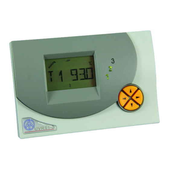
Page 62: Operation
Operation The large majority contains all of the icons needed for all of the important information as well as a plain text field. Navigation with the co-ordination keys has been adapted to the display arrangement. ... -
Page 63: The Main Level
The main level Temperature Temperature Temperature Sensor 1 Sensor 2 Sensor 6 Volume flow Wind velocity External value 1 Only displayed Only displayed Only displayed if if S6 = VSG if S6 = WS external DL is activated External value 9 Legionella function Speed stage Only displayed if... - Page 64 T1 to T6 Displays the value measured at the sensor (S1 - T1, S2 - T2, etc.). The display (unit) depends on the settings of the sensor type. Display types: Temperature in °C Radiation in W/m Digital status 1 = (radiation sensor) ON (digital input) If in the SENSOR menu (main menu ENTER/Men ) one sensor is set to OFF , then...
-
Page 65: Changing A Value (Parameter)
Display of the system’s status. Depending on the program selected, various Stat: system statuses are monitored. If any problems have occurred, this menu contains all of the information. The navigation keys on the parameter level ( , ) allow you to select the icons Par: under the temperature display and the text line. -
Page 66: The Parameter Menu Par
The parameter menu Par Code to enter Version number Program number menu Linking of output Priority assignment Max limit switch-off (only for programs threshold (3 times) with priority Max limit switch-on Min limit switch-on Min limit switch-off only displayed threshold (3 times) only displayed (3 times) (3 times) -
Page 67: Brief Description
Assign free outputs Automatic / manual Automatic / manual (according to mode (3 times) for mode (2 times) for diagram) outputs 1 – 3 the control outputs Brief description Code to enter the menu. The other menu items are only displayed once the CODE correct code has been entered Ver sion number... -
Page 68: Code Number Code
Code to enter Version number Program number menu Code number CODE The other menu items of the parameter menu are only displayed after input of the correct code number ( code number 32 ). Software version VER Display of the software ver sion. It cannot be changed as it indicates the intelligence of the device and must be provided if there are any queries. -
Page 69: Priority Assignment Pa
Priority assignment PA Priorities can be set for program diagrams with multiple consumers on one heat generator. This menu item is only displayed for program diagrams with priority. The priority assignment (output assignment) is adapted to the specific program diagram. The priority assignment always refers to the pumps. - Page 70 Example: Program number 0 Max limit switch-off Max limit switch-on Min limit switch-on value value value Min limit switch-off Difference switch- Difference switch- value on threshold off threshold max When a sensor reaches this temperature, the output is blocked. (ex works = 75°C) max ...
- Page 71 Schematic representation of setting values...
-
Page 72: Time
Time Example: 16:34 = Display of time. The time is set by pressing enter and the navigation keys . Press the key again to switch between minutes and hours. Time The correct setting of date and time can be useful even if the time windows are NOTICE: not used. -
Page 73: Time Window Time W (3 Times)
Time window TIME W (3 times) Setting of 3 time windows A total of 3 time windows are available. For each time window, the outputs that affect the window can be freely set. Each output can have up to 3 time windows assigned to it. If an output is released in a time window (between the switch-on / off times), the remaining time windows do not affect this output any longer. -
Page 74: Timer Function Timer
Timer function TIMER Setting the Timer function The timer function can be assigned to any output. It is possible to specify a release time (during this time the output is released) and a block time (during this time the output is blocked). Release time and block time are active alternatively. -
Page 75: Assignment Of Free Outputs A2/A3 <= Off
Assignment of free outputs A2/A3 <= OFF Outputs which do not have a fixed assignment in the diagram (diagram 0 to 159) can be linked to other outputs. A3 deactivated A3 activated (as A3 switches with time switch output) A3 switches with A3 switches when A3 switches when A1 and A2 are ON... -
Page 76: Automatic / Manual Mode
Automatic / manual mode The three outputs are set to automatic mode and can be set to manual mode for O AUTO test purposes ( O ON , O OFF ). To indicate manual mode a flashing hand symbol appears. An active output (pump is running) is indicated when a number (LED) appears next to the display. -
Page 77: The Menu Men
The menu Men Language Code to enter the Sensor menu menu System protection Start function Solar priority function only displayed for progr. with priority After-running time Pump speed Control outputs of outputs control Function check Heat quantity Legionella- counter function External sensors Drain-back via data link... -
Page 78: Brief Description
Brief description The menu contains basic settings to determine additional functions such as the sensor type, the system protection functions, etc. Navigation and changes are done as usual with the keys , while the dialogue is only set up in the text line. As the settings in the menu can change the basic features of the control unit, only a technician who has the code can open this level. -
Page 79: Language Deut, Engl, Inter
Language DEUT, ENGL, INTER Language selection: The entire menu can be switched to the desired user language even before the code is provided. The following languages are available: German ( DEUT ), English ( ENGL ) and international ( INT ) for French, Italian and Spanish. Factory settings are made in German ( DEUT ). -
Page 80: Sensor Settings
Sensor settings Sensor S6 has been taken in this example as it has the most setting possibilities. PT1000 Radiation sensor Fixed value Transfer of values Digital input Fixed value entry Transfer of values setting Sensor OFF Volume flow Litres per pulse encoder (encoder) Only displayed (only S6) -
Page 81: Sensor Type
S6 = VSG). (ex works = 0.5) Setting range: 0.0 to 10.0 litres/pulse in increments of 0.1 litre/pulse Wind sensor: Only connected to input S6 , to read in the pulses of the wind sensor WIS01 from Technische Alternative (1Hz per 20km/h). -
Page 82: Creating A Mean (Average) Av
Creating a mean (average) AV Setting of the time in seconds over which an averaging of the measured value should be carried out (ex works = 1.0s). Example: AV1 1.0 Create an av erage of sensor S1 for 1.0 seconds For simple measurements, 1.0-2.0 should be selected. -
Page 83: System Protection Function Sys Pf
System protection function SYS PF Collector excess Collector excess temperature limit 1 temperature limit 2 Frost protection Frost protection function 1 function 2 Collector cooling Anti-blocking protection function Two collector excess temperature limiter functions and two frost protection functions are available. -
Page 84: Collector Excess Temperature Limit Cet
Collector excess temperature limit CET Steam builds up when the system is not circulating. When it automatically switches on again, the pump does not have the pressure to lift the fluid level above the highest point in the system (collector feed line). If there is no circulation, the load on the pump is enormous. This function allows the pump to be blocked above a set collector temperature threshold ( max ... -
Page 85: Collector Frost Protection Frost
Collector frost protection FROST This function is disabled ex works and is only necessary for solar power systems that run without antifreeze: In the south, the energy from the solar cylinder suffices to keep the collector at a minimum temperature for the few hours below freezing. At min of 2°C on the collector sensor, the settings in the chart release the solar pump and block it again at min ... -
Page 86: Collector Cooling Function Coolf
Collector cooling function COOLF With the aid of this function the cylinder is allowed to cool overnight so that the following day heat can be taken in again. If the selected sensor (cylinder temperature) has exceeded the set threshold temperature the selected output remains switched on during the specified period for so long until it is under-run again. -
Page 87: Anti-Blocking Protection Asc
This output switches itself on as soon as the selected sensor exceeds the temperature threshold in the set time period. If a control output is allocated to the output, then the analog stage 100 is additionally output at this control output. Setting range: Combinations of all outputs (ex works = OP1) Speed stage with which the pump is to run (only output O1, ex works = 30) Anti-blocking protection ASC... -
Page 88: Start Function Startf (Ideal For Tube Collectors)
Start function STARTF (ideal for tube collectors) In the morning, solar power systems sometimes do not “start” quickly enough because the warm heat transfer medium does not reach the collector sensor. Flat collector panels and forced-circulation vacuum tubes generally lack sufficient gravitational force. The start function tries to release a rising interval while the collector temperature is constantly monitored. -
Page 89: Priority Prior
Start function ON/OFF (ex works = ex works = OFF) ON / OFF Setting of coll ector sensor (ex works = S1, ex works = S2). COLL Setting range: S1 to S6 Radiation sensor GBS 01 - non-standard accessory: Indicates a sensor input if a radiation sensor is used. - Page 90 After the rinsing time (1, 3), the computer calculates the increase in collector temperature. It detects whether the set waiting time WTL has been reached to heat the collector to the priority temperature. In the second case, the unit waits until the priority has been reached to switch.
-
Page 91: After-Running Time Art
Radiation value ( r adiation th reshold) in W/m above which rinsing is allowed. Without a radiation sensor, the computer calculates the necessary temperature increase for the long-term mean that launches rinsing from this value. (ex works = 150W/m Setting range: 0 to 990W/m in increments of 10W/m O ut p uts used for r insing. -
Page 92: Pump Speed Control Psc
Pump speed control PSC Pump speed control PSC is not suitable for electronic or high efficiency pumps. Warning! The values in the following description are by way of example only; they must, in all cases, be matched to the system! Absolute value Desired value for Differential control... - Page 93 Waveform Two waveforms are available for motor control. (ex works = WAVEP) Wave packets - only for circulating pumps with standard motor dimensions. Here, WAVEP individual half cycles are bled in to the pump motor. The pump runs on pulses and only produces a smooth flow of the heat transfer medium when the rotor’s moment of inertia has been overcome.
-
Page 94: Control Output Cop 0-10 V / Pwm (Twice)
Control output COP 0-10 V / PWM (twice) Control output 1 Control output 2 Control output number Different functions of the control output Control output 5V power supply 0 - 10V output deactivated PWM output Error message Error message (upon error 0 to (upon error 10V switchover) inverse switchover... - Page 95 The following settings are only possible in 0-10V and PWM modes. Warning! The values in the following description are by way of example only; they must, in all cases, be matched to the system! Control output Output for release Absolute value control Desired value for Differential control...
- Page 96 The control outputs are deactivated at the factory. In the active state, they can be enabled by an assigned output, i.e. by an output specified by the schematic and the program number. If a control output (0 to 10V or PWM) is activated, then the analogue stage is displayed in the basic menu after the measured values below “ANL 1“...
-
Page 97: Absolute Value Control
maintaining a sensor Absolute value control S1 can be kept at one temperature (such as 50°C) very well by using the speed control. If the solar radiation is reduced, S1 becomes colder. The control unit then lowers the speed and hence the flow rate. However, that causes the warm-up time of the heat transfer medium in the collector to increase, thus increasing S1 again. -
Page 98: Event Control
D ifferential c ontrol in n ormal operation between sensors S 1 and S 2 . DC N12 (ex works = --) Setting range: DC N12 to DC N65, DC I12 to DC I65) DC -- = differential control is disabled. The d esired v alue for d ifferential control is 10K . - Page 99 Stability problems The speed control has a PID controller. It ensures an exact and fast adjustment of the actual value to the set point. In applications such as solar power systems or feed pumps, the following parameters should be left in factory settings. With a few exceptions, the system will run stably.
- Page 100 Output mode, output limits Depending on the pump version, the control mode of the pump can be normal (0 – 100 “solar mode“) or inverse (100 – 0, “heating mode“). There can also be specific requirements for the limits of the control range. These can be found in the information of the pump manufacturer.
-
Page 101: Function Check F Chck
Function check F CHCK Some countries only grant support for the installation of solar power systems if the control unit monitors the system, especially to detect a lack of circulation. The function check is disabled ex works. ON/OFF Circulation OFF/ Circulation check AUTO/MANUAL for output 1... -
Page 102: Heat Quantity Counter Hqc (3 Times)
Setting possibilities : CIRC -- = circulation check is disabled CIRC A = circulation checks are performed according to the diagram (only the solar circuits in the diagrams shown) CIRC M = circulation checks can be set manually for each output. The following menu items are only displayed if the circulation checks have been set to “manual”. - Page 103 Heat quantity counter number ON/OFF Sensor supply line Sensor return line No volume flow Fixed volume flow encoder Volume flow encoder Assigned output Share of antifreeze Temperature difference adjustment Delete counter...
- Page 104 select / disable heat counter (ex works = OFF) ON/OFF S ensor input for s upply l ine temperature (ex works = S4) Setting range: S1 to S6 Input of the flow sensor E1 to E9 Value from external sensor via DL S ensor input for r eturn l ine temperature (ex works = S5) Setting range: S1 to S6 Input of the return sensor...
- Page 105 Temporary temperature dif ference between the flow and return sensor (Maximum display ±8.5 K, above an arrow is displayed). If both sensors are immersed in one bath for test reasons (with both thus measuring the same temperatures), the device should display “ DIF 0 ”. Sensor and measurement equipment tolerance may, however, lead to a displayed difference under DIF .
- Page 106 "Step by step" setting of the heat quantity counter You have the option of using 2 different volume flow encoders: the pulse encoder VSG, the FTS….DL, which is connected to the data link. If you do not use a volume flow encoder, then you can only set a fixed volume flow. In the following, the necessary settings are displayed "step by step".
- Page 107 FTS….DL (Example: Fitting in the return, only 1 FTS4-50DL in use, use of an external sensor for the flow which is connected to the FTS4-50DL) The FTS4-50DL is connected to the data link (external sensor), hence: menu "EXT DL", setting of the volume flow encoder in the display of the external sensor "E1": 11 (address 1, index 1) Setting the sensor temperature of the FTS4-50DL: Menu "EXT DL", in the display "E2": 12 (address 1, index 2)
-
Page 108: Legionella Function Legion
Legionella function LEGION Protective function against the formation of legionella. If the specified cylinder temperature DV is not reached at the monitored sensor within the time interval for the duration of the runtime RT , then an output ( e.g. electric heating element ) is switched on for the duration of the runtime RT and maintained via the temperature threshold DV . -
Page 109: External Sensors Ext Dl
Minimum runtime. If the specified cylinder temperature DV is not reached at the monitored sensor within the time interval for the duration of the runtime RT , then an output is switched on for the duration of the runtime RT and maintained via the temperature threshold DV . -
Page 110: Drain-Back Function Drainb
Drain-Back Function DRAINB This additional function may only be activated with programs for a collector field with a consumer (e.g. program 0, 80 112, 432, etc.) or program 4. With drain-back solar thermal systems the collector area is emptied outside the circulation time. - Page 111 ON/OFF Radiation sensor Radiation value Radiation threshold Outputs filling Filling time Stabilisation time Blocking time Volume flow sensor Minimum flow low Low water water Start attempts counter ON / OFF Drain-back function ON /OFF (ex works = OFF) Specification of a sensor input if a Global radiation sensor is used. If no temperature sensor is available, then only the collector sensor temperature is referenced for starting of the drain-back function.
- Page 112 Radiation value (radiation threshold) in W/m , above which filling is permitted when using a radiation sensor. (ex works = 150W/m Adjustment range: 0 to 990W/m in 10W/m steps Outputs, that are responsible for filling. It is also possible to use a "booster pump". The output for the 2nd pump must be a free output, that is not already being used for other purposes.
-
Page 113: Status Display Stat
Status display Stat The stats display offers information in special system situations and when problems occur. It is primarily intended for us with solar power systems but can also be useful with other diagrams. The status display can, however, then only be set off due to an active function check or defective sensors S1 to S6. - Page 114 Function check disabled or : or : or : Function check Collector - excess Legionella Drain-back low water disabled temperature - switch- protection function off is active is active Function check activated or : or : or : or : Function check Collector –...
-
Page 115: Troubleshooting
Troubleshooting In general, all of the settings in the menus Par and Men and the terminals should be checked if there is an error. Malfunction, but “realistic” temperatures: Check the program number. Check the thresholds for on/off and the set differential temperatures. Have the thermostat and differential thresholds been reached? ... -
Page 116: Table Of Settings
Table of settings If the control system fails unexpectedly, all of the settings should be reset for initial configuration. In this case, problems are inevitable if all of the setting values are entered in the following table. If there are questions, this table has to be provided. Only then is a simulation possible to reproduce the error. - Page 117 Sensor type SENSOR Sensor S1 PT1000 Average determ. AV1 1,0 s Sensor S2 PT1000 Average determ. AV2 1,0 s Sensor S3 PT1000 Average determ. AV3 1,0 s Sensor S4 PT1000 Average determ. AV4 1,0 s Sensor S5 PT1000 Average determ. AV5 1,0 s Sensor S6 PT1000...
- Page 118 Solar priority PRIOR Radiation sensor GBS Radiation value RTH 150 W Rinse outputs OPS Waiting time WTL 5 min Pump run time PRT 20 min After-running time ART AT 1 s AT 2 AT 3 Pump speed control PSC Abs.value control. AC Desired value DVA 50°C °C...
- Page 119 Heat counter HQC Heat counter HQC 1 ON/OFF Feed SSL Return SRL Volume flow encoder or Volume flow V 50 l/h Outputs OP Share of antifreeze SA Heat counter HQC 2 ON/OFF Feed SSL Return SRL Volume flow encoder or Volume flow V 50 l/h Outputs OP Share of antifreeze SA...
-
Page 120: Technical Data
Technical data 210 ... 250V~ 50-60 Hz Power supply: max. 2.8 W Power input: 3.15 A fast-acting (device + output) Fuse: 3x 1mm² H05VV-F conforming to EN 60730-1 Supply cable: plastic: ABS, flame resistance: Class V0 to UL94 Norm Case: II –... -
Page 121: Information On The Eco-Design Directive 2009/125/Ec
[W] consumption [W] consumption UVR61-3 1.49 / 2.37 1.8 / 2.8 Definitions according to Official Journal of the European Union C 207 dated 03/07/2014 The classification applied is based on optimum utilisation and correct application of the products. - Page 122 EC- DECLARATION OF CONFORMITY Document- Nr. / Date: TA12004 / 19.11.2012 Company / Manufacturer: Technische Alternative elektronische SteuerungsgerätegesmbH. Address: A- 3872 Amaliendorf, Langestraße 124 This declaration of conformity is issued under the sole responsibility of the manufacturer. Product name: UVR61-3, UVR61-PV Product brand: Technische Alternative GmbH.
- Page 124 Legal notice These assembly and operating instructions are protected by copyright. Use outside the copyright requires the consent of the company Technische Alternative elektronische Steuerungsgerätegesellschaft m. b. H.. This applies in particular to reproductions, translations and electronic media.
Need help?
Do you have a question about the UVR61-3 and is the answer not in the manual?
Questions and answers