Technische Alternative UVR610S General Programming Information, User Manual
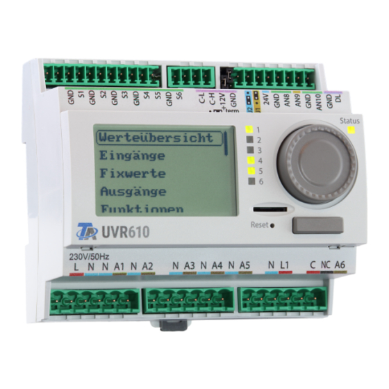
Freely programmable universal controller
Hide thumbs
Also See for UVR610S:
- Installation instructions manual (24 pages) ,
- Installation instructions manual (24 pages)

Subscribe to Our Youtube Channel
Related Manuals for Technische Alternative UVR610S


Summary of Contents for Technische Alternative UVR610S
- Page 1 www.ta.co.at UVR610 FREELY PROGRAMMABLE UNIVERSAL CONTROLLER General programming information User manual Manual Version 1.17 English...
-
Page 3: Table Of Contents
Table of contents Principles ..............6 Device overview . - Page 4 Table of contents Designation and transmission condition ..........41 Transmission condition .
- Page 5 Table of contents Deleting, renaming and sending saved files ..........66 Save...
-
Page 6: Principles
Principles Principles This manual is designed as a guide to programming directly on the device, but also provides impor- tant information about the elements required for programming with the TAPPS2 programming soft- ware (functions, inputs and outputs, etc.). Programming with TAPPS2 is always recommended. It enables the programmer to draw (= program) all program operations in the form of a graphical flow chart and to define parameters for them ac- cordingly. -
Page 7: Planning Basics
Principles Planning basics To ensure efficient programming, the following order must be adhered to: A prerequisite for programming and defining parameters is an accurate hydraulic scheme. Using that scheme, you must define what should be controlled and how. Based on the required control functions, you must define the sensor positions and draw them on the scheme. - Page 8 Principles View with previously defined designations Entries are made up of letters, numbers and symbols entered consecutively. Up to 100 different designations can be defined by the user. The maximum number of characters per designation is 24. Designations defined previously are available for all elements (inputs, outputs, functions, fixed val- ues, bus inputs and outputs).
-
Page 9: General Information On Programming Parameters
Principles General information on programming parameters for inputs, outputs, fixed values, functions, default settings, and CAN and DL inputs and outputs. If displayed, entries must be confirmed with If you want to discard your entries, select Example: Entering numeric values The following window is displayed for entering numerical values: Name of the numeric value, setting range Current numeric value... -
Page 10: Date / Time / Location
Date / time / location Date / time / location The entry Date / Time / Location can be found under the general set- tings. The system value parameters are displayed first •Time zone – 01:00 means the time zone "UTC + 1 hour". UTC stands for "Universal Time Coordinated", also known as GMT (= Greenwich Mean Time). -
Page 11: Power Reserve
The values for geographical latitude and longitude are used to determine the location-specific solar data. That data can be used in functions (e.g. shading function). The factory default settings for the GPS data are for the location of Technische Alternative Amalien- dorf, Austria. -
Page 12: Value Summary
Value summary Value summary This menu item shows the current values for inputs 1 – 16, the DL inputs and the analogue and digital CAN inputs. If an entry is selected, the corresponding values are listed below. -
Page 13: Inputs
Inputs Inputs The controller has 6 inputs for analogue signals (measurements), digital signals (ON/OFF) or pulses. This menu displays the inputs with their designation and the current measurements or status. Example of a programmed system; input 1 is still unused: Programming the parameters Sensor type and measured variable Once the required input is selected, the sensor type can be defined. - Page 14 Select the measured variable: • Temperature • Select the sensor type: KTY (2 kΩ/25°C = formerly Technische Alternative's standard type), PT 1000 (= current standard type), room sensors: RAS, RASPT, THEL thermocouple, KTY (1 kΩ/25°C), PT 100, PT 500, Ni1000, Ni1000 TK5000 •...
- Page 15 Inputs Pulse input Inputs 1 - 6 can capture pulses with max. 10 Hz and a pulse duration of at least 50 ms. Select the measured variable Wind speed A quotient must be entered for "Wind speed". This is the signal frequency at 1 km/h. Example: The WIS01 wind sensor issues one pulse (=1Hz) per second at a wind speed of 20 km/h.
-
Page 16: Designation
Inputs Designation Enter the input designation by selecting a predefined designation from various designation groups or from the user defined designations. Sensor type Analogue / Temperature: • General • Generator • Consumer • Line • Climate • User (user defined designations) You can also assign a number from 1 to 16 to every designation. -
Page 17: Sensor Check For Analogue Sensors
Inputs Sensor check for analogue sensors When "Sensor check" is active (setting: "Yes"), a short circuit or a lead break will automatically gen- erate an error message. Example: Sensor error When "Sensor check" is active, Sensor error is available as an input variable for functions: status "No" for a sensor that is working correctly and "Yes"... -
Page 18: Resistance Table For Various Sensor Types
1000 1045 1091 1114 1138 1186 1235 1285 1337 1390 1444 1500 TK5000 The standard type used by Technische Alternative is PT1000. KTY (2 kΩ) was the factory-fitted standard type until 2010/2011. PT100, PT500: As these sensors are more susceptible to external interference, their sensor leads must be screened and the Average time should be increased. -
Page 19: Outputs
Outputs Outputs The controller has 10 outputs. The entry Outputs in the main menu takes you to an overview. Outputs are shown with their name and current status. Example: Programming the parameters Once the required output is selected, the output type can be defined. First, you must specify the basic output type. - Page 20 Outputs Outputs 1+2, 3+4, 5+6, 7+8 and 9+10 as an output pair These outputs can be used as single switching outputs or as an output pair together with the follow- ing switching output (e.g. to control a mixer drive). The output pairs 1+2, 3+4 and 5+6 are available as standard. The output pairs 7+8 and 9+10 require the use of auxiliary relays (relay modules).
- Page 21 Outputs All switching outputs A start delay and a run-on time can be defined for all switching outputs All outputs Manual mode can be restricted to certain user groups (User, Technician, Expert) for all outputs Outputs 7 to 10 as analogue outputs These outputs provide a voltage between 0 and 10 V, e.g.
- Page 22 Outputs Outputs status of the analogue outputs For the output status you can define whether the ON status should be is- sued above or below an adjustable threshold. Example: If the analogue output is over 3.00 V, the output status switches from OFF to ON. Depending on the technical attributes of the pump being controlled, it may thus be possible to set the output status to be ON only when the pump is actually running.
- Page 23 Outputs Display in the Outputs menu The display in the menu shows the operating state of the analogue output. The output status can be changed by selecting it. •Auto: Output issued according to the source and scaling •Manual: Adjustable value •Manual/OFF: Output issued according to "Dominant off"...
-
Page 24: Designation
Outputs Designation Enter the output designation by selecting a predefined designation from various designation groups or from the user defined designations. • General • Climate • User (user defined designations) You can also assign a number from 1 to 16 to every designation. Overview of outputs Outputs Switching outputs and output pairs 7 –... -
Page 25: Output Meter
Outputs Output meter Selecting this icon allows you to see the hours run and pulses (times switched on) for every output. Example: For output 1, the meter readings since 28-06-2019 can be viewed. If you tap the button, you will be asked whether you want to delete the total meter readings and the "Previous day"... - Page 26 Outputs Below the hours run, the pulses (how many times switched on) can be viewed. The meter shows the total number of pulses (times switched on), the number of pulses on the previous day and the number today. If you tap the button, you will be asked whether you want to delete the pulses counted today.
-
Page 27: Display Of Links
Outputs Display of links When you select this icon, the output's links to the functions will be displayed. Example: In this example, output 1 is controlled by two functions, and it has just been switched on by function 1 (DHW demand 1). Tapping a function takes you directly to the menu for that function. -
Page 28: Functions
Functions Functions Functions are created, programmed and linked in this menu. This section only describes how func- tions and links are created. For more detailed information on the various function modules, see the Programming: functions instructions. Creating a new function Under Type you select which function is to be created. -
Page 29: Fixed Values
Fixed values Fixed values In this menu you can define up to 64 fixed values, which can be used as input variables for functions, for example. When this item is selected in the main menu, the fixed values already defined are displayed together with their designation and their current value or status. -
Page 30: Programming The Parameters
Fixed values Programming the parameters Example: Fixed value 1 Fixed value type Once the required fixed value is selected, the fixed value type can be defined • Digital • Analogue • Pulse Digital Select the measured variable: • On / Off •... -
Page 31: Analogue
Fixed values Analogue Select from a wide range of function quantities For fixed values, the function quantity "Time" (shown as: 00:00) is also available. After assigning the designation, you must define the permitted limits and the current fixed value. The value can be adjusted in the menu within those limits. -
Page 32: Pulse
Fixed values Pulse A fixed value of this type allows short pulses to be generated by tapping it in the menu “Fixed values”. A pulse can also be triggered in the menu of the fixed value by tap- ping. Function quantity Select the function quantity: When activated, either an ON pulse (from OFF to ON) or an OFF pulse (from ON to OFF) will be generated, depending on the settings made here. -
Page 33: Messages
Messages Messages This menu item displays activated messages. Example: Message 1 is active. Pop-up window If a message is triggered, a pop-up window is displayed. Message/warning/fault/error: Type of message displayed Overtemperature (ex.): Name of message (designation of the initiating message function) Warning tone off: Deactivation of beeping sound Delete message: The message cannot be deleted until the cause of the... -
Page 34: Can Bus
CAN bus CAN bus The CAN network allows communication between CAN bus devices. When analogue or digital val- ues are sent via CAN outputs, other CAN bus devices can utilise those values as CAN inputs. This menu contains all of the information and settings needed to set up a CANopen network. Up to 62 CAN bus devices can be operated in one network. -
Page 35: Datalogging
CAN bus Datalogging This menu is not visible in the User mode. In this menu, the settings for datalogging are defined via CAN bus or on the SD card of the controller for analogue and digital values. Datalogging Settings Here, you can define whether the logging values are stored on the SD card for the controller and if so, at what intervals. -
Page 36: Can Settings
CAN bus CAN settings Node Define a unique CAN node number for the device (setting range: 1 – 62). The device with node num- ber 1 provides the time stamp for all other CAN bus devices. Designation Every controller can be given its own designation. Bus rate The standard bus rate of the CAN network is 50 kbit/s (50 kBd), which is specified for most CAN bus devices. -
Page 37: Can Analogue Inputs
CAN bus CAN analogue inputs Up to 64 CAN analogue inputs can be programmed. They are defined by specifying the transmission node number and the number of the transmission node's CAN output. Node number After the node number of the transmission node is entered, the other settings can be specified. The number of a CAN analogue output is taken from the device with that node number and applied here. -
Page 38: Can Bus Timeout
CAN bus Example: CAN bus timeout Define the timeout time for the CAN input (minimum value: 5 minutes). As long as the information continues to be read from the CAN bus, the network error for the CAN input will be "No". If the value has not been updated for longer than the set timeout, the network error changes from "No"... -
Page 39: Value At Timeout
CAN bus Value at timeout This setting is only displayed if "Measured variable" is set to "User". If the timeout time is exceeded, you can define here whether the controller should issue the last value transmitted ("Unchanged") or a definable substitute value. Sensor correction This setting is only displayed if "Measured variable"... -
Page 40: Can Digital Inputs
CAN bus CAN digital inputs Up to 64 CAN digital inputs can be programmed. They are defined by specifying the transmission node number and the number of the transmission node's CAN output. Their parameters are programmed in almost exactly the same way as for the CAN analogue inputs. Under Measured variable / User the Display for the CAN digital input can be changed from Off / On to No / Yes and you can define whether the controller should issue the last status transmitted ("Un- changed") or a definable substitute status when the timeout time is exceeded. -
Page 41: Designation And Transmission Condition
CAN bus Designation and transmission condition Every CAN analogue output can be given its own designation. The designation can be selected from various designation groups or can be user defined, as for the inputs. Example: Transmission condition Example: If the current value has changed by more than 1.0 K compared to the last If change >... -
Page 42: Can Digital Outputs
CAN bus CAN digital outputs Up to 32 CAN digital outputs can be programmed. They are defined by specifying the source in the controller. Their parameters are programmed in exactly the same way as for the CAN analogue outputs except for the transmission conditions. -
Page 43: Dl Bus
DL bus DL bus The DL bus acts as a bus cable for various sensors and/or for datalogging by C.M.I. or D-LOGG. The DL bus is a bidirectional data link and is only compatible with products from Technische Al- ternative. The DL bus network operates independently of the CAN bus network This menu contains all of the information and settings needed to set up a DL bus network. -
Page 44: Dl Input
DL bus DL input Sensor values from DL bus sensors are transferred via a DL input. Up to 32 DL inputs can be programmed. Example: Programming the parameters of DL input 1 Select: Analogue or digital DL bus address and DL bus index Every DL sensor must have its own DL bus address. -
Page 45: Designation
DL bus Designation Every DL input can be given its own designation. The designation can be selected from various desig- nation groups or can be user defined, as for the other controller inputs. Example: DL bus timeout As long as the information continues to be read from the DL bus, the network error for the DL input will be "No". -
Page 46: Sensor Correction
DL bus Sensor correction This setting is only displayed if "Measured variable" is set to "User". The value of the DL input can be corrected by applying a fixed differential value. Sensor error This setting is only displayed if sensor check is active and "Measured variable" is set to "User". When "Sensor check"... -
Page 47: Dl Output
DL bus DL output Analogue and digital values can be transmitted to the DL bus network via a DL output. For example, a digital command to activate an O2-DL O2 sensor can be output. Example: Programming the parameters of DL output 1 ... -
Page 48: M-Bus
M-Bus M-Bus The M-Bus is a master/slave system for reading data from energy and volume meters (electricity, heat, water, gas). The M-Bus input is designed for up to 4 M-Bus "unit loads". Up to 4 M-Bus meters, each with 1 unit load, can therefore be connected. - Page 49 M-Bus For a connected M-Bus device, device information and data received can be read by pressing the "List" button. After 255 access attempts, the access number is reset to 0.
-
Page 50: M-Bus Input
M-Bus Device information Information about the device and manufacturer is shown at the top. Received data Up to 128 values per meter can be shown here. The order is defined according to the telegram ad- dress and the start byte. In addition, the value read is shown with the unit. The manuals issued by the M-Bus device manufacturers contain more details about the values. -
Page 51: Sensor Check
M-Bus If you select "User def.", you can select a unit of your own, a sensor correction and, if the sensor check is set to active, a monitoring function. Every M-Bus input is assigned a unit, which can differ from the unit used by the M-Bus device. A wide range of units is available to choose from. - Page 52 M-Bus Example: Temperature If the measurement is below 10 °C, 50 °C will be issued; if it exceeds 100 °C, 70 °C will be issued.
-
Page 53: Cora Devices
CORA devices CORA devices CORA devices can be connected via CORA-DL. They are connected at the controller's DL bus. Devices connected via CORA-DL do not affect the DL bus load. This menu allows CORA devices to be set and programmed wirelessly, and transmitted values to be imported. -
Page 54: Parameters
CORA devices Parameters Pairing status indicates whether the wireless connection with the device is established. Device information opens a menu similar to the Version menu of the paired device, in addition to displaying the date and time of the last packet received wirelessly. -
Page 55: Modbus
Modbus Modbus (Only for UVR610-MODB controllers) The UVR610-MODB controller can be used as master or slave for Mod- bus RTU485. In this menu, the Modbus settings are made and the in- puts/outputs are programmed. Only the Modbus RTU485 protocol is supported. ... -
Page 56: Modbus Input
Modbus Modbus input Inputs can be programmed as analogue (numerical value) or digital (On/Off or Yes/No). Unit Every Modbus input Type must be assigned a unit, Select Analogue/Digital as the transmitted data Device/function/address is dimensionless. A wide Master mode: Details range of units is availa- about the Modbus device... -
Page 57: Modbus Output
Modbus Modbus output Outputs can be programmed as analogue (numerical value) or digital (On/Off or Yes/No). First, select the value to Transmission condition be transmitted (function, Analogue: fixed value, system If change > 1.0 K: value, DL bus, CAN bus). If the current value has The two following entries changed by more than... -
Page 58: General Settings
General settings General settings Some menu items are only displayed in expert and/or technician mode. This menu allows settings to be made which then take effect for all other menus and displays. Language Select the display language. Contrast Screen contrast in percent. Brightness Select the brightness of the display to match the surroundings (setting range: 5.0 –... -
Page 59: Simulation
General settings Simulation Option of activating the simulation mode (only possible in Expert mode): • No averaging of the outside temperature in heating circuit control. • All temperature inputs are measured as PT1000 sensors, even if a different sensor type is defined. -
Page 60: User Defined Designations
General settings User defined designations In this menu, you can enter, change or delete user defined designations for all elements of the con- troller. This menu can only be selected from within the Technician or Expert level. View with designations defined previously Entries are made up of letters, numbers and symbols entered consecutively. -
Page 61: User
User User Current user Select whether the user is an Expert, Technician or User. To enter the Technician or Expert level a password must be entered, which can be set by the program- mer. When function data is loaded from the Expert or Technician level, the controller returns to the User level and applies the programmed passwords. - Page 62 User List of permitted actions User Displays and permitted actions • Function overview with options for control • Access to main menu only if enabled for "User" in the "General settings" • Summary of values • Inputs: display only, no access to the parameters •...
-
Page 63: Version And Serial Number
Version and serial number Version and serial number This menu displays the serial number, internal production data and the name of the current function data. The serial number is also visible on the controller's rating plate (upper side panel). -
Page 64: Data Administration
Data administration Data administration Can only be operated in technician or expert mode. You can perform the following actions in this menu: • Save, load or delete function data • Load firmware • Load or delete a function overview • Display the status of the data transfer •... -
Page 65: Load
Data administration Load... Function data can be loaded from the SD card onto the controller or other x2 devices. Multiple func- tion data can be saved to the SD card. The data transfer is only possible after a technician or expert password has been entered for the tar- get device. -
Page 66: Deleting, Renaming And Sending Saved Files
Data administration Deleting, renaming and sending saved files In order to rename or delete saved files, tap the plus symbol. The following options then appear for selection: Return from this selection by tapping the icon again. Delete file A confirmation prompt appears, which you can confirm by tapping Tapping cancels the action. -
Page 67: Save
Data administration Save... The current function data can be saved to the SD card. You can give the function data a name of your own. More than one set of function data can be saved. Example: In this example there are already several sets of function data saved on the SD card. If you want to save the function data under a new name, tap on the button. -
Page 68: Firmware Load
Data administration Firmware Load... Firmware (= operating system, file *.bin) can be loaded from the SD card onto the controller or other x2 devices (Except: other UVR16x2) on the CAN bus. More than one operating system version may be saved on the SD card. The data transfer is only possible after a technician or expert password has been entered for the tar- get device. -
Page 69: Total Reset
Data administration Total reset A total reset can only be carried out from the Technician or Expert level and requires confirmation when prompted. A total reset deletes the function modules, the parameter settings of all in- puts and outputs, bus inputs and outputs, fixed values and system values. The settings for the CAN node number and the CAN bus rate are retained. -
Page 70: System Values
System values System values This menu displays the status of system values that are available for selection as the source for func- tion input variables and CAN and DL outputs. The system values are divided into 4 groups: General system values When programmed accordingly, these system values allow monitoring of the controller system. - Page 71 System values Time system values Date system values • Second (seconds of the current time) • Day • Minute (minutes of the current time) • Month • Hour (hour of the current time) • Year (without the century) • Second pulse •...
-
Page 72: Led Indicator Light
LED indicator light LED indicator light The indicator light can indicate a variety of statuses by means of three colours. Indications at controller start Indicator light Explanation The controller is booting up (= start routine after switching on, resetting or Steady red light updating) Steady orange light... - Page 76 Legal notice These operating instructions are protected by copyright. Use outside the copyright requires the consent of the company Technische Alternative RT GmbH. This applies in particular to reproductions, translations and electronic media. Technische Alternative RT GmbH A-3872 Amaliendorf, Langestraße 124 Tel.: +43 (0)2862 53635...
Need help?
Do you have a question about the UVR610S and is the answer not in the manual?
Questions and answers