Table of Contents

Subscribe to Our Youtube Channel
Related Manuals for Salicru DC POWER-S DC-36-S


Summary of Contents for Salicru DC POWER-S DC-36-S
- Page 1 UNINTERRUPTIBLE POWER SUPPLY (UPS) + LIGHTING FLOW DIMMER STABILIZERS (ILUEST) + SWITCH MODE POWER SUPPLY + STATIC INVERTERS + PHOTOVOLTAIC INVERTERS + VOLTAGE STABILIZERS AND POWER LINE CONDITIONERS DC POWER SYSTEMS DC POWER-S Series USER'S MANUAL...
- Page 3 Terminals (X11) - (X12) and (X47) - (X48). 7.6. Connection to AC mains. Terminals (X1), (X2), (X3) and (X4). 7.7. Connection of the loads. 7.7.1. No DC outgoing distribution. Terminals (X6) and (X9). 7.7.1.1. Floating output. 7.7.1.2. Output with the positive earthed. SALICRU...
-
Page 4: Acknowledgement Letter
We remain at you entire disposal for any further information or any query you should wish to make. Yours sincerely. SALICRU ˆ The equipment here described can cause important physical damages due to wrong handling. This is why, the installation, maintenance and/or fixing of the here de- scribed equipment must be done by our staff or specifi- cally authorised. -
Page 5: Information For Safety
As usual They will be supplied in hardcopy. • The following terms are used in the document to be referred ˆ «DC Power-S, equipment, rectifier-charger, system, DC energy system or unit».- DC Switch Mode Power Supply. SALICRU... -
Page 6: Quality And Standard Guarantee
Quality and standard guarantee. 3.1. Declaration of the management. 3.3. Environment. Our target is the client’s satisfaction, therefore this Management This product has been designed to respect the environment has decided to establish a Quality and Environmental policy, by and has been manufactured in accordance with the standard means of installation a Quality and Environmental Management ISO 14001. - Page 7 When its appropriate, an additional explanatory annex documents will be edited for those The DC Power-S system can be supplied in the following ver- equipments manufactured with special requirements. sions: SALICRU...
-
Page 8: Equipment Views
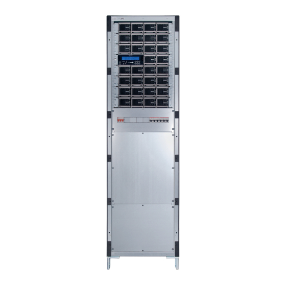
Any DC Power-S has protections, nevertheless depending on the power and voltage they can vary: (RV) • Input. Circuit breaker protection for currents up to 160 A or fuses for higher currents. • Batteries. (F/Q1A) (F/Q3) (F/Q2A) Circuit breaker protection, fuse switch or fuses plus switch, cont rect depending on the battery current and voltage. - Page 9 • • • • • • (F/Q1A) (F/Q1B.. 1*) (F/Q2B.. 2*) (F/Q2A) • • • (F/Q3) • • • (F/Q2) (F/Q6A.. 6*) (TC) (TB) ••• For three-phase mains R-S-T-N Fig. 5. Front view of a system in a 605x605x1315 mm cabinet. SALICRU...
- Page 10 ) (AS cont rect • • • • • • • • • • • • (F/Q1A) • • • • • • (F/Q1B.. 1*) (F/Q2B.. 2*) (F/Q2A) • • • (F/Q3) • • • (F/Q2) (F/Q6A.. 6*) (TC) (TB) •••...
- Page 11 • • • • • • (F/Q1B.. 1*) (F/Q2B.. 2*) (F/Q2A) (F/Q3) • • • • • • (F/Q2) (F/Q6A.. 6*) (TC) (TC) (TB) ••• For three-phase mains R-S-T-N Fig. 7. Front view of a system in a 605x605x2115 mm cabinet. SALICRU...
- Page 12 ) (AS cont rect • • • • • • • • • • • • (F/Q1A) • • • • • • (F/Q1B.. 1*) (F/Q2B.. 2*) (F/Q2A) (F/Q3) • • • • • • (F/Q2) (F/Q6A.. 6*) (TC) (TC) (TB) •••...
- Page 13 (TC) (TC) (TC) (TB) ••• Fig. 9. Front view of 605x605x1315 mm battery cabinet. SALICRU...
- Page 14 (TC) (TC) (TC) (TB) ••• Fig. 10. Front view of 605x805x1315 mm battery cabinet. USER MANUAL...
- Page 15 (TC) (TC) (TC) (TB) ••• Fig. 11. Front view of 605x605x2115 mm battery cabinet. SALICRU...
- Page 16 (TC) (TC) (TC) (TB) ••• Fig. 12. Front view of 605x805x2115 mm battery cabinet. USER MANUAL...
-
Page 17: Dimensional Drawings
4.1.1. Dimensional drawings. Table top case dimensions. Rectifier module dimensions. 19'' subrack dimensions. SALICRU... - Page 18 Case with casters dimensions. Cabinet dimensions: 605x605x1315 mm. 605x805x1315 mm. USER MANUAL...
- Page 19 Dimensions for equipment cabinets or batteries, regardless illustration: 605x605x2115 mm. 605x805x2115 mm. 805x805x2115 mm. Fig. 13. Dimensional drawings. SALICRU...
-
Page 20: Connection Parts
4.1.2. Legends corresponding to the Connection parts and instructions of the communication module (M equipment views. See EN030* user's manual. Connection parts. Protection and manoeuvring parts. (X1) AC input terminal, phase R. (F/Q1A) Input or general input circuit breaker or fuses, two (X2) AC input terminal, phase S. - Page 21 Fixing points of the telescopic guide (GS) of the sub- rack. (PI) Elevator parts -feet-. (PR) Cable gland for cable entry. (R103) Probe of temperature/battery floating voltage. (RN) Cable gland slot for entering the connection cables. (RU) Casters. (RV) Cooling grid. SALICRU...
-
Page 22: Rectifier Module
4.1.3. Nomenclature. Rectifier module. DC-50-S 48-230 WCO EE553000-3 Rectifier with particular specifications of the client. “Made in Spain” marking (customs only). Neutral equipment brand. Nominal input voltage. Nominal output voltage. Series of the equipment. Total output current of the module at floating voltage Rectifier. -
Page 23: Battery Cabinet
It means that the equipment is supplied neither the corresponding batteries nor accessories (bolts and electrical cables). Under request is possible to supply the needed accessories to install and connect the batteries. SALICRU... -
Page 24: Single Line Diagram
Single line diagram, All rectifiers are autoadressing, Plug-in and Hot swap type through the front of the cabinet, and it is not needed any special description and structural tool, just a screwdriver. This feature allows removing the faulty modules and/or insert new modules into the system, without the diagram of the system. -
Page 25: Com Ports
To solve this phenomena, the Control Module includes the Smart mode. This operating mode entail in shutdown the redundant SALICRU... - Page 26 5.3. Structural diagram as an example. Control Module Communication Module Outgoing distribution (F/Q1B) (F/Q2B) (F/Q1C) (F/Q2C) (F/Q1A) (F/Q2A) (F/Q6A) (F/Q1*) (F/Q2*) (F/Q2) (F/Q6B) Batteries (F/Q6*) F/Q3 Low voltage Device Contactor Batteries can be fitted in the same cabinet of the rectifier, in one or more separate cabinets or due to the configura- tion in both cabinets.
-
Page 27: Equipment Reception
Cardboard packaging, polyethylene foam PE and anti- static plastic bag. Fig. 17. Unpacking process of system in a cabinet. SALICRU... - Page 28 ˆ The equipment will be nude over the pallet with its plastic ˆ Systems with flooded batteries or NiCd batteries and re- bag «». Remove it by pulling from the top. movable shelves, fix the cabinet to the floor through the holes in its plinth-base (BZ) before fitting the batteries.
-
Page 29: Installation
(PF) and remove the screws tion: ) and (t ), as well as the covers (TB) and (TC). The Depending on the case, remove the rear and side – connection parts will be at sight. SALICRU... - Page 30 7.1. Operative for inserting and In cabinets of systems and/or batteries, where the battery shelves are removable, there will removing modules from the not be blind covers and they will have front door. system. • Finally, after doing the connection and/or erection tasks, it is mandatory to leave the cabinet/switch the cover/s put it or them back and the front door closed.
- Page 31 Procedure to remove a module. strictly, the polarity of the battery connection and the sup- ˆ Loosen both screws with safety washer (t ) to release the plied circuit diagram together with the documentation and the module handle (AS DC Power-S. SALICRU...
-
Page 32: To Keep In Mind
7.4. Main protective earth terminal or • Battery handling and connection, will be done or su- pervised by personnel with specific knowledge only. rod (X5) and/or (X5A). Before doing any action, disconnect the batteries. Check that current is not present and there is not dangerous voltage be- tween both terminal ends of the battery set. - Page 33 (fuse switches or circuit breakers), to be installed being connected to the equipment have the same by the client. type of connection of itself, otherwise it will mean a risk for the personnel and the destruction of the installation and annexes equipments. SALICRU...
-
Page 34: Communication Module
7.7.2. With DC outgoing distribution. ˆ Terminal strip as an option. Terminals (X6A.. 6*) and (X9A.. 9*). An outgoing terminal strip can be supplied with the corre- sponding positive terminals to each protection (X6A.. 6*). Connect the negative of the loads to these terminals. 7.7.2.1. - Page 35 (X42), corresponding to the the auxiliary contact ignore that reference. alive pole (the one not connected to earth). Table 2. Correlation between auxiliary terminals and the function of the protection or switch, of the cabinet of the system. SALICRU...
- Page 36 ˆ In battery cabinets separate from DC Power-S: Auxiliary terminal Protection or switch function of the In case of systems with more than one cabinet, the reference battery cabinet – electrolyte level probe can be found in the cabinet Batteries (X43) that has the terminal (X25A).
-
Page 37: Shutdown Of The System
See section 9. • The system has a control module described in the user's manual EN021*. By means of itself, the DC Power-S can be managed and monitored and control the operating mode. • Start up the loads. SALICRU... -
Page 38: Control Module
Optical indications of the rectifiers. 9.1. Optical indications. a) Correct output indication. Green colour led. (b) Standby module indication, it doesn't supply output voltage. Yellow colour led. With leds (a) + (b) turned on, in green and yellow colour respectively, the indication as warning mode means that the rectifier is working at maximum current conditions. -
Page 39: Maintenance
Once the new module is fitted in the operative system, it will be auto-addressed and it will be started up automatically. SALICRU... -
Page 40: General Technical Specifications
11. Annexes. 11.1. General technical specifications. DB9 connector (COM3) RS485. Exclusive from COM2 INPUT 3 dry contacts, extendable to 9. See Single phase 220 / 230 / 240. Dry contacts (RELAYS) user'rs manual EN030*, communication AC voltage (V) Three phase 3x380 / 3x400 / 3x415 module (5 wires: 3 phases + N +PE) Battery voltage compensation... - Page 41 (for example the one supplied by the battery), it is continuous any current that always maintain the polarity. • GND.- The term ground, as its name states, refers to the po- tential of the earth surface. SALICRU...
- Page 42 : ............................................................................................................................................................................................................................................................................................................................................................................................................................................................................................................................................................................................................................................................................................................................................................................................................................................................................................................................................................................................................................................................................................................................................................................................................ USER MANUAL...
- Page 43 : ............................................................................................................................................................................................................................................................................................................................................................................................................................................................................................................................................................................................................................................................................................................................................................................................................................................................................................................................................................................................................................................................................................................................................................................................................ SALICRU...
- Page 44 BARCELONA Tel. +34 93 848 24 00 902 48 24 00 (Only Spain) Fax. +34 94 848 11 51 salicru@salicru.com Tel. (S.T.S.) +34 93 848 24 00 902 48 24 01 (Only Spain) Fax. (S.T.S.) +34 93 848 22 05 sst@salicru.com...
Need help?
Do you have a question about the DC POWER-S DC-36-S and is the answer not in the manual?
Questions and answers