Sign In
Upload
Manuals
Brands
ATI Technologies Manuals
Measuring Instruments
SmartTachSmartTach
ATI Technologies SmartTachSmartTach Manuals
Manuals and User Guides for ATI Technologies SmartTachSmartTach. We have
1
ATI Technologies SmartTachSmartTach manual available for free PDF download: User Manual
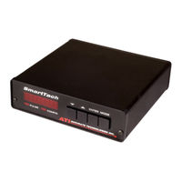
ATI Technologies SmartTachSmartTach User Manual (110 pages)
Universal Speed Measurement Tool
Brand:
ATI Technologies
| Category:
Measuring Instruments
| Size: 0 MB
Table of Contents
Table of Contents
3
Introduction
7
About this Manual
10
Technical Support
10
Get to Know Smarttach
11
Smarttach Connections
11
Important Safety Warnings
12
INSTALLATION General Information
16
Placement of the Smarttach Unit
16
Selecting the DC Power Source
16
Figure 2 - 1: Spark Input Examples
17
Figure 2 - 2: Trigger Input Examples
17
List of Figures
17
Pulse Input Connection
17
Installation of Wiring Cables
18
Other Connections
18
Analog Output Connection
19
COM Port Connection
19
I/O Port Connection
20
Power Supply Connection
18
Tachsensor Connection
18
CONFIGURATION General Information
22
Operating Modes
22
Measure
22
Configure
23
Default Configuration Values
23
Configuration Controls
23
Figure 3 - 1: Parameter Group Display
23
Figure 3 - 2: Parameter List Display
23
Using the Pushbutton Switches
24
Pushbutton Switch Functions
24
Changing Parameters
25
Figure 3 - 3: Pushbutton Functions
25
Figure 3 - 4: Parameter Edit Navigation
26
Configuration Examples
27
Configuration Example 1
27
Configuration Example 2
27
Configuration Example 3, 4
28
Parameters
31
Measurement Parameter
32
Displayed Engineering Units
33
Patterns/Pulses Per Cam/Dyno Revolution
34
Figure 4 - 1: Parameter 2 Pulse Examples
34
Pulses Per Pattern
35
Figure 4 - 2: Parameter 3 Pulse Examples
35
Engineering Unit Conversion Factor
36
Engineering Conversion Units
37
Input Signal Conditioning Select
38
Multi-Strike Filter
40
Pulses Per Measurement
41
Spark Input Threshold Level
42
Trigger Input Level
44
Trigger Input Polarity
45
Trigger Input Attenuator
46
Trigger Input 5V Pull-Up
47
Trigger Input Threshold Level
48
Trigger Input Hysterisis Level
49
Analog Output Mode
50
Analog Output Scaling
51
Analog Output Offset
52
Analog Output Maximum Voltage Limit
53
Analog Output Minimum Voltage Limit
54
Analog Output Test Voltage
55
Analog Output Update Period
56
Range Output Function
57
Range Output Measurement Condition
59
Range Output Voltage Condition
60
Range Output "A" Value
61
Range Output "B" Value
62
Range Output "C" Value
63
Range Output "D" Value
64
Range Output Test State
65
Analog Input Update Period
66
Analog Input Filter
67
Display Brightness
68
Display Update Period
69
RS-232 Baud Rate
70
RS-232 DTR/DSR Handshake
71
A0 - Trigger Input High Peak Voltage
72
A1 - Trigger Input Low Peak Voltage
73
A2 - Power Supply Input Voltage
74
A3 - Auxiliary Input Voltage
75
F0 - Load Parameters from Memory
76
F1 - Save Current Parameters to Memory
77
F2 - Reset Current Parameters
78
Operation
81
General Information
82
Measure Mode
82
Display Maximum/Minimum Attained Values
82
Pushbutton Switch Functions
83
Measure Mode
83
Figure 5 - 1: Normal Measurement Display
83
Figure 5 - 2: Maximum Value Display
83
Figure 5 - 3: Minimum Value Display
83
Using Other Instruments with the Analog Output Signal
84
Using Range Outputs
84
Range Output Example 1
85
Figure 5 - 4: Range Output Overspeed
85
Range Output Example 2
86
Figure 5 - 5: Range Output Overspeed/Low Oil Pressure
86
Troubleshooting
87
General Information
88
Common Problems
88
Display Does Not Light
88
Display Is Always 0 or Erratic
90
Incorrect Value Displayed
90
Incorrect Analog Output Voltage
90
Erratic Analog Output Voltage
91
Figure 6 - 1: Erratic Analog Output
91
Figure 6 - 2: Normal Analog Output
91
Common Faults and Configuration Errors
92
Improper Setting of Input Conditioning Select (06)
92
Improper Setting of Spark Input Threshold Level (10)
92
Improper Input Polarity Setting (21)
92
Incorrect Setting of Patterns/Pulses Per Cam Rev (02)
92
Cables Routed Near Spark Plug Wires or Coils
92
Bad Connections in Wiring Cables
92
Warranty
95
Limitation of Remedy
96
Product Changes
96
Appendices
97
Parameter Groups and Default Values
98
Connectors and Pin-Outs
101
Rear Panel
101
Analog Output
101
Pulse Input
101
COM Port
101
Figure a - 1: Connector Placement
101
Tachsensor - I/O Connector
102
Power Supply Input
102
Smarttach Accessories
103
TS1 Tachsensor
103
IP1 Inductive Pickup
103
Figure a - 2: Smarttach Accessories
103
Advertisement
Advertisement
Related Products
ATI Technologies SR-176
ATI Technologies SR-221
ATI Technologies SR-61
ATI Technologies SX400
ATI Technologies SolarJet SOL-P2
ATI Technologies SOL-GP
ATI Technologies SC29T
ATI Technologies SOL-D
ATI Technologies SIGNATURE AT6002
ATI Technologies SIGNATURE AT6005
ATI Technologies Categories
Video Card
Amplifier
Measuring Instruments
Industrial Equipment
Water Heater
More ATI Technologies Manuals
Login
Sign In
OR
Sign in with Facebook
Sign in with Google
Upload manual
Upload from disk
Upload from URL