
Related Manuals for Grundfos Fire DNF


Summary of Contents for Grundfos Fire DNF
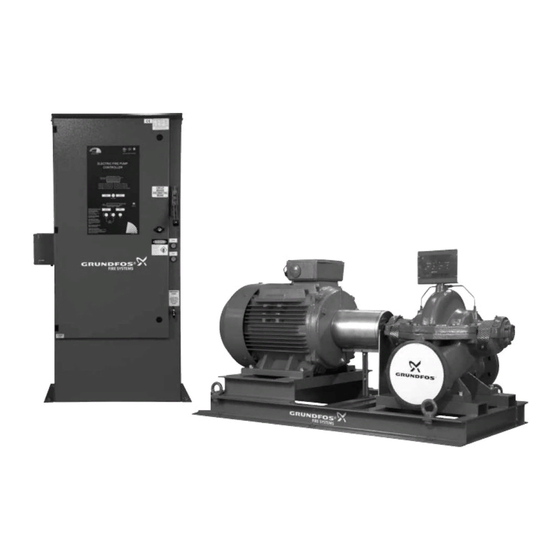
- Page 1 GRUNDFOS INSTRUCTIONS Fire DNF, Fire HSEF - electric Installation and operating instructions...
- Page 2 Declaration of conformity GB: EC declaration of conformity We, Grundfos, declare under our sole responsibility that the products Fire DNS and Fire HSEF, to which this declaration relates, are in conformity with these Council Directives on the approximation of the laws of the EC Member States: —...
-
Page 3: Table Of Contents
English (GB) Installation and operating instructions 14.3 Pump Original installation and operating instructions. 14.4 Motor 14.5 Coupling CONTENTS 14.6 Controller Page Fault finding Symbols used in this document Service, spare parts and accessories Applications Warranty Delivery, transport, storage Further documentation Delivery Dimensions, weights and motor data Transport... -
Page 4: Symbols Used In This Document
1. Symbols used in this document 2. Applications The Grundfos Fire HSEF and DNF pump sets are designed for Warning fire systems for supplying water to hose reels, fire hydrants and sprinkler systems. If these safety instructions are not observed, it may result in personal injury. -
Page 5: Storage
4.3 Motor 7. Cover the pump with a weather-resistant cover of waterproof The pumps are driven by a 2- or 4-pole Grundfos MMG-E motor paper or plastic material to protect it against dirt and dust. (15-315 kW) or a Siemens motor (355 kW). All motors are 8. - Page 6 4.4.2 Controller design The controller is placed in a control cabinet mounted on the base frame (compact unit) or delivered separately for wall- or floor- mounting (flex unit). The controller is operated by means of the control panel in the cabinet door. See fig. 3. The control cabinet supplies the motor with the electricity required for starting and operating the motor.
- Page 7 [Cut-out] B2 (fig. 4) This button is used to set the pressure limit for stopping the pump. It is enabled with a DIP switch. See section 5.1 Settings via DIP switches. It is also used when setting the controller. See 5.2 Settings via display.
- Page 8 Additionally, indicator I8 shows that the pump is running. 4.4.5 Display D2 (pressure status) The display shows the pressure status of the system. Pos. Indication Description Reset I > 130 % of I Overcurrent more than 20 We 23:23:32 seconds. I <...
-
Page 9: Functions
4.5 Functions Start delay In systems with several pumps, it may be necessary to set a start Control and monitoring take place via the functions described in delay to prevent all motors from starting at the same time. the following subsections. The start delay is selectable. -
Page 10: Settings
Monitoring of ambient temperature (option C7) Unlocking or locking of buttons for setting of cut-in and cut- out pressures (switch No 1) If a thermostat for measuring the room temperature is installed, the optional control relay CR20 will be activated when the When DIP switch "Lock-Unlock"... - Page 11 Menu 3 (timers) Menu 11 (pressure log) In this menu, two different timers can be set. In this menu, the user can view the pressure log. OFF Tim: 600 Auto Pressure Log Tim: 10 SAVE The first line shows date/month and time, the second line shows a) Run time before automatic stop the pressure.
-
Page 12: Identification
6. Identification The fire pump set can be identified by the type designation on the nameplate. See fig. 8. 6.1 Type keys An explanation of the type designation is given in the following subsections. 6.1.1 Type key for fire pump set Example DNF: Fire /260... -
Page 13: Nameplates
6.1.2 Type key for controller Pos. Description Example GPA - 380-416 / 50 / 3 / 50 Type designation Product number Type GPA: Fire pump controller for Serial number direct-on-line starting Type designation of driver Actual impeller diameter GPY: Fire pump controller for star- delta starting Rated flow rate Power output... - Page 14 Nameplate for DNF pump Pos. Description cos phi at 60 Hz Bearing, non-drive end Serial number AV. H. A. CASTELO BRANCO. 630 SAO BERNARDO DO CAMPO - SP - BRASIL Connection D/Y CENTRIFUGAL FIRE PUMPS - END SUCTION 20SV APPROVED Nameplate type MODEL DNF 80-25...
-
Page 15: Technical Data
The motor type is consent of Grundfos or its authorised stated on the motor nameplate. See fig. 14, pos. 4. representatives. Disregard of this warning can... -
Page 16: Effect Of Ambient Temperature And Altitude On Motor Output
8.10 Effect of ambient temperature and altitude on 9.2 Foundation motor output It is advisable to install the fire pump set on a concrete foundation which is heavy enough to provide permanent and rigid support for If the ambient temperature exceeds +40 °C (fig. 16), or the motor the entire fire pump set. -
Page 17: Vibration Dampening
9.3 Vibration dampening 9.4 Levelling To prevent vibrations from being transmitted to the building and Warning pipework, it is advisable to fit expansion joints and vibration The fire pump set should only be lifted by dampers. See fig. 18. qualified personnel. When lifting the entire fire pump set, never use the lifting eyes of the individual components. -
Page 18: Pipework
9.5 Pipework 9.6 Bypass A bypass to the suction source, if required, should be made as Warning shown in fig. 23. The distance between bypass pipe and pump Do not put fingers, hands, arms, etc. into the discharge flange must be at least ten pipe diameters. suction or discharge openings or into any other opening, such as that of the air relief valve. -
Page 19: Alignment
9.9 Alignment Step Action Warning Before removing the coupling guard, make sure that the fire pump set has been switched off and The distance between cannot be accidentally switched on. the shaft ends must correspond to the value Pump and motor are connected by a standard or spacer coupling for s stated in the from FLENDER. -
Page 20: Separate Control Cabinet
9.10 Separate control cabinet Step Action The controller must be located as close as practical to the motor and within sight of the motor. Warning Installation in hazardous locations and potentially explosive environments is not Place the foil where allowed. The controller must be located or needed. -
Page 21: Electrical Connection
10. Electrical connection Connection of external equipment • If the controller is to lock other equipment (option A7), see the Warning label in the control cabinet. Check that the supply voltage specified on the • If a motor heater is to be connected, see the label in the nameplate of the control cabinet corresponds to control cabinet. -
Page 22: Connection To Optional Control Relays
10.4 Connection to optional control relays 11.2 Start-up If more detailed information about operating and alarm conditions 1. Close the isolating valve on the discharge side of the pump. is required, conductors can be connected to the optional control Open the isolating valve on the suction side of the pump. relays for transferring operating and alarm messages to for Open the isolating valve to the test pipe. -
Page 23: Operation
The pump must start before this point. If the pump does not start before the resistance Note point, contact Grundfos. 3. Lock the emergency start handle in closed position. 4. Switch on the power supply with the circuit breaker. -
Page 24: Taking The Pump Out Of Operation
If the configuration has been made correctly, this window will be 12.4.2 Printing of data shown when starting HyperTerminal: If the controller is equipped with a printer, it is located behind a plastic cover. The cover protects the printer from humidity and dust. -
Page 25: Maintenance
It is recommended to place a this will create excessive friction and cause damage to the maintenance contract with Grundfos. packing or shaft sleeve. Maximum packing life can be expected with a leakage of minimum of 40 to 60 drops per minute. -
Page 26: Fault Finding
15. Fault finding Warning Before carrying out any service of the pump, make sure that the fire pump set cannot accidentally start. Fault Cause Remedy 1. Pump delivers no or too a) Wrong direction of rotation. Interchange two phases of the power supply. little water. -
Page 27: Service, Spare Parts And Accessories
The usage of non-original spare parts and accessories renders any liability on behalf of Grundfos for resulting damages null and void. Any malfunctions which cannot be repaired should only be corrected by Grundfos or authorised specialist companies. -
Page 28: Dimensions, Weights And Motor Data
19. Dimensions, weights and motor data 19.1 Dimensions and weights Data apply to standard versions. Fire HSEF, compact unit with controller on base frame, 2-pole Fire pump set Pump Motor Height, Height, Dimensions Suction Discharge Pump type Motor type Weight suction discharge Weight... - Page 29 1050 MMG 315M-E 1682 1150 HSEF 6-12 MMG 315LA-E On request 1785 1250 MMG 315LB-E 1867 1330 Fire DNF, flex unit with separate controller, 2-pole Fire pump set Pump Motor Height, Height, Dimensions Suction Discharge Pump type Motor type Weight...
- Page 30 Fire HSEF, flex unit with separate controller, 4-pole Fire pump set Pump Motor Height, Height, Dimensions Suction Discharge Pump type Motor type Weight suction discharge Weight Weight [kW] L x W x H port port [kg] port port [kg] [kg] [mm] [inch] [inch]...
- Page 31 Fire HSEF, flex unit with separate controller, 4-pole Fire pump set Pump Motor Height, Height, Dimensions Suction Discharge Pump type Motor type Weight suction discharge Weight Weight [kW] L x W x H port port [kg] port port [kg] [kg] [mm] [inch] [inch]...
-
Page 32: Motor Data
2980 188/108 MMG 315M-E 2980 222/128 HSEF 6-12 3 x 380-41 ∆/660-690 Y MMG 315LA-E 2980 270/156 MMG 315LB-E 2980 330/190 Fire DNF, 2-pole Voltage Speed Start Pump type Motor type -------------- - [kW] [min ⁄ MMG 160L-E 18.5 2940 32.5/18.8... -
Page 33: Disposal
This product or parts of it must be disposed of in an environmentally sound way: 1. Use the public or private waste collection service. 2. If this is not possible, contact the nearest Grundfos company or service workshop. Subject to alterations. - Page 35 Turkey 20th km. Athinon-Markopoulou Av. Тел.: +7 (375 17) 286 39 72, 286 39 73 New Zealand GRUNDFOS POMPA San. ve Tic. Ltd. Sti. P.O. Box 71 Факс: +7 (375 17) 286 39 71 GRUNDFOS Pumps NZ Ltd. Gebze Organize Sanayi Bölgesi GR-19002 Peania E-mail: minsk@grundfos.com...
- Page 36 97502645 0913 ECM: 1121739 www.grundfos.com...
Need help?
Do you have a question about the Fire DNF and is the answer not in the manual?
Questions and answers