
Related Manuals for Grundfos Fire DNF


Summary of Contents for Grundfos Fire DNF
- Page 1 GRUNDFOS INSTRUCTIONS Fire DNF, Fire HSEF - diesel Installation and operating instructions...
- Page 2 Declaration of Conformity We, Grundfos, declare under our sole responsibility that the products Fire DNS and Fire HSEF - diesel, to which this declaration relates, are in conformity with these Council Directives on the approximation of the laws of the EC Member States: —...
-
Page 3: Table Of Contents
14.4 Diesel engine CONTENTS 14.5 Coupling Page 14.6 Controller Symbols used in this document Fault finding Applications Service, spare parts and accessories Delivery, transport, storage Warranty Delivery Further documentation Transport Storage Dimensions, weights and engine data 19.1 Dimensions and weights Product description 19.2 Engine data... -
Page 4: Applications
2. Applications the hands if dropped. The Grundfos Fire HSEF and DNF pump sets are designed for fire systems for supplying water to hose reels, fire hydrants and sprinkler systems. -
Page 5: Storage
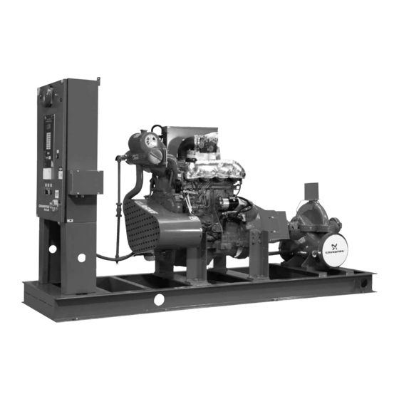
2 and 3. They show an HSEF pump set 3. If the pump has not been connected to the pipework, cover the with a Grundfos horizontal split case pump and a 4-cylinder pump suction and discharge flanges with full natural rubber... -
Page 6: Controller
Fire pump set with JU4H and JU6H diesel engine, front view Fig. 2 Fire pump set with JU4H and JU6H diesel engine, back view Fig. 3 Pos. Component Pos. Component Diesel injection pump Base frame Fuel suction pump Controller Fuel filter Pump Cooling water circuit Automatic air release valve (not shown) - Page 7 4.2 Pump 4.3 Engine The fire pump set comes with a Grundfos HSEF horizontal split 4.3.1 General description case pump or a Grundfos DNF end-suction pump. The pumps are The pump is driven by a stationary 4-stroke diesel engine from FM-approved and UL-listed.
-
Page 8: This Equipment Starts Automatically
CAUTION DO NOT RUN ENGINE WITHOUT AIR FILTER INSTALLED. PERSONAL INJURY OR ENGINE DAMAGE MAY RESULT. C13191 WARNING THIS EQUIPMENT STARTS AUTOMATICALLY USE EAR PROTECTION C13187 Control panel of JU/JW diesel engine Fig. 5 Pos. Operating element Description Pos. Indicator Description Instructions for Instructions as how to start the... - Page 9 Control panel of JX diesel engine Fig. 6 Pos. Operating element Description Shows relevant engine Power view gauge parameters and alarm messages. Shows the voltage supplied by Voltmeter, battery 1 or 2 battery 1 or 2. Shows the number of Operating hour counter operating hours.
- Page 10 The control panel of the JX6 diesel engine is equipped with a If an alarm occurs, the alarm message will be shown instead of diagnostic gauge. See fig. 7. the engine parameters. Example of alarm message, JX6 Fig. 9 SPN (Suspect Parameter Number) and FMI (Failure Mode Identifier) codes will be shown along with a description of the problem and the corrective action needed.
- Page 11 The design of the control panel in the cabinet door is shown in 4.4 Controller fig. 11. It consists of a display, 16 indicator lights and six buttons. 4.4.1 General description The display shows the status of the fire pump set and gives The fire pump set is controlled via a Tornatech controller access to seven menus for setting.
- Page 12 The internal components of the controller are shown in fig.12. [BATTERY No. 1 MANUAL CRANK] A3 and [BATTERY No. 2 MANUAL CRANK] A4 (fig. 10, pos. 6 and 8) These buttons can be used only when the main switch is set to manual mode.
- Page 13 The following operating and alarm messages are shown in fig. 13, 4.4.4 Display indications pos. 7: The display shows the status of the fire pump set and alarm messages. It also gives access to the setting menus of the Status Description controller.
- Page 14 4.4.5 Indicator lights on control panel and alarm bell Sixteen indicator lights show the status of the controller and the engine. See the table below. The table also shows when the alarm bell will ring, and whether the fault indication is reset automatically (A) or manually (M) by turning main switch A2 (fig.
-
Page 15: Functions
If the engine is running, indicator light "Engine Run" (fig. 11, pos. 4.5 Functions 10) will be on, and the display will show "Automatic Start". Control and monitoring take place via the functions described in The alarms "Engine Fail to Start" (fig. 11, pos. 11) and "Fail when the following subsections. - Page 16 The pump-on-demand relay AR28 (option B8) will be activated if Start delay a start condition is present (remote start contact open, deluge In systems with several pumps, it may be necessary to set a start valve open, pressure under cut-out pressure with engine running) delay to prevent all engines from starting at the same time.
- Page 17 Monitoring of system pressure on discharge side If the system pressure measured by the built-in pressure sensor of the controller is above the set limit, indicator light "Controller Trouble" (fig. 11, pos. 16) will be on, and the alarm bell will ring. The display will show the alarm message "System Overpressure", and standard relay AR4 will be activated.
-
Page 18: Operating And Alarm Messages
4.6 Operating and alarm messages The operating status is shown on the control panel by means of the display and the indicator lights. Some alarms will cause the alarm bell to ring. See section 4.4.4 Display indications and 4.4.5 Indicator lights on control panel and alarm bell. In the following two subsections, operating and alarm messages are shown together with the contact status of the standard and optional alarm relays. - Page 19 4.6.2 Alarm messages Status of Status of optional Operating status Indicator light Display text Alarm bell Reset standard relay alarm relay The engine did not start Engine Fail to Start AR1: activated AR9: activated after six attempts. There is a pump demand, but the engine Fail when Running AR1: activated...
- Page 20 Status of Status of optional Operating status Indicator light Display text Alarm bell Reset standard relay alarm relay The system pressure measured by the built-in pressure sensor of the controller is above the System Controller Trouble AR4: deactivated AR27: activated set value.
-
Page 21: Settings
5. Settings Automatic or manual stop (S10-2) When DIP switch S10-2 is in position "ON", the controller is set to Settings are made by means of the two DIP switches and the automatic stop. The engine will stop after the minimum run time display menu. -
Page 22: Settings Via Display
5.2 Settings via display Menu 4 (timers) In this menu, three different timers can be set: Seven menus enable setting of several parameters: a) Start delay • date and time (menu 1) The delay time can be set from 0 to 60 seconds. The factory •... -
Page 23: Identification
6. Identification The fire pump set can be identified by the type designation on the nameplate. See fig. 15. 6.1 Type keys An explanation of the type designation is given in the following subsections. 6.1.1 Type key for fire pump set Example DNF: Fire /260... - Page 24 6.1.2 Type key for engine Example H UL 2 Engine type J: John Deere basic engine adapted by CLARKE UK LTD Engine series U: standard range 4-cylinder engine = 4.5 litres 6-cylinder engine = 6.8 litres W: special range 6-cylinder engine = 8.1 litres X: standard range 6-cylinder engine = 12.5 litres Number of cylinders...
- Page 25 6.1.3 Type key for controller Example BCE10-12 B1, C3, C5,C7 Range GPD: Controller for diesel-powered fire pump set Type of earth Negative earth Positive earth Battery voltage [V] Mounting Mounted on base frame For floor mounting For wall mounting Language English French Spanish...
-
Page 26: Nameplates
6.2 Nameplates Nameplate for HSEF pump All important data of the fire pump set are stated on the fire pump set nameplate (fig. 15), pump nameplate (fig. 16 and fig. 17), engine nameplate (fig. 18) and controller nameplate (fig. 19). CENTRIFUGAL FIRE PUMP Nameplate for fire pump set HORIZONTAL SPLIT - CASE... -
Page 27: Technical Data
Nameplate for diesel engine 7. Technical data 7.1 Complete fire pump set Dimensions and weights, see section 19.1. Sound pressure level The sound pressure level depends on the diesel engine. It was measured without a silencer, one metre away from the fire pump set. -
Page 28: Battery
Diameter of exhaust gas pipe: See section 19.2. pump was originally purchased without the Discharge heat exchanger: 3/8". consent of Grundfos or its authorised Amount of oil: See section 19.2. representatives. Disregard of this warning can API-classification CF4. result in pump failure and serious personal injury Type of oil: Viscosity 15W-40. -
Page 29: Ambient Temperature
8.8 Ambient temperature 9. Installation Minimum ambient temperature The installation must be carried out in • +4 °C if the engine includes preheating. accordance with the following instructions. Non- Caution • +10 °C if the engine does not include preheating. compliance may result in functional faults which will damage the pump components. -
Page 30: Vibration Dampening
Expansion joints Expansion joints provide the following functions: • Absorption of thermal expansion and contraction of pipework caused by variations in liquid temperature. • Reduction of mechanical influences in connection with pressure surges in the pipework. • Isolation of structure-borne noise in the pipework (only rubber bellows expansion joints). -
Page 31: Pipework
9.5 Pipework 9.6 Bypass A bypass to the suction source, if required, should be made as Warning shown in fig. 28. The distance between bypass pipe and pump Do not put fingers, hands, arms, etc. into the discharge flange must be at least ten pipe diameters. suction or discharge openings or into any other opening, such as that of the air relief valve. -
Page 32: Exhaust Gas System
9.11 Exhaust gas system Checking the horizontal parallel offset 1. Rotate the shaft so that the reference "AB" on the flywheel Warning disc or the circumference of the drive shaft flange (against the flywheel) is in 12 o’clock position. See fig. 30. The exhaust gas system must be installed correctly according to local regulations and must 2. -
Page 33: Separate Fuel Tank
Checking the alignment Warning Before removing the coupling guard, disconnect the battery cable. 1. Disconnect the battery (negative pole). 2. Remove the coupling guard. Flanged 3. Measure the distance "Z" at the rubber element of all axially pump bolted points. See fig. 33. The distance must be 50 mm. If the alignment is correct, proceed with step 4. -
Page 34: Separate Control Cabinet
9.14 Separate control cabinet Connection of external sensor signals • If the fuel tank is installed separately, connect the float switch The controller must be installed as close as practical to the (NO) for low level to terminals 23-24 and the one for high level engine and within sight of the engine. -
Page 35: Connection To Standard Alarm Relays
10.3 Connection to standard alarm relays 10.4 Connection to optional alarm relays If operating and alarm messages are to be transferred for If more detailed information about operating and alarm conditions instance to a building management system, conductors can be is required, conductors can be connected to the optional alarm connected to the standard alarm relays (fig. -
Page 36: Start-Up
11. Start-up 11.3 Setting of cut-in and cut-out pressures To enable setting, DIP switch S10-1 must be set to "ON". Warning See section 5.1 Settings via DIP switches. Start-up may only be carried out by authorised It is important to set the cut-out pressure first. It must be lower personnel. -
Page 37: Manual Operation
12.2 Manual operation 12.4 Retrieving and printing data The fire pump set can be started manually for a test run, servicing 12.4.1 Retrieving data via the RS 232 port or temporary switching on or off during start-up, the fire pump set As standard, the controller has an RS 232 port (fig. - Page 38 Paper replacement Weekly test The paper must be thermal paper and be correctly oriented. Click [Weekly Test] to access the settings of the weekly test. The following operations must be followed to replace the paper: The following window appears: 1. Unscrew the axle and remove the empty roll. 2.
-
Page 39: Taking The Pump Out Of Operation
It is recommended to place a The fire pump set must not be running. Note maintenance contract with Grundfos. 1. Close the isolating valve on the discharge side. Warning 2. Close the isolating valve on the suction side. - Page 40 To read the oil level, pull out the oil dipstick (JU4H, JU6H and 14.3 Pump JX6H), or unscrew it (JW6H) (fig. 43, pos. 29). Oil level measurements are to be taken when the engine is cold. The oil Warning level must be between the minimum and maximum marks on the Before carrying out maintenance work on the oil dipstick.
- Page 41 Draining the condensate The condensate collector of the fuel filter is under the fuel filter (fig. 52, pos. A). Loosen the knurled nuts of the condensate collector. Collect the fuel containing water in a suitable container and dispose of it in an environmentally sound way. Tighten them when the diesel fuel runs clean, i.e.
- Page 42 14.4.7 Venting of fuel system JW6H Warning Fuel expelled under pressure can penetrate the skin and cause serious injuries. The pressure must therefore always be released before the fuel pipes are disconnected. Before repressurising, tighten all pipes securely. JU4H and JU6H Fig.
-
Page 43: Coupling
[Lamp Test/Silence] button B3. If an Worn V-belts must be replaced. See service instructions. indicator light fails, please contact Grundfos. All screw connections on the brackets and all frame connections must be checked once a year to ensure a secure fit. Any loose connections must be tightened. -
Page 44: Fault Finding
15. Fault finding Warning Before carrying out any service of the pump, make sure that the fire pump set cannot accidentally start. Fault Cause Remedy 1. Pump delivers no or too a) Air in suction pipe. Fill storage container with water. Vent pump. little water. -
Page 45: Service, Spare Parts And Accessories
The usage of non-original spare parts and accessories renders any liability on behalf of Grundfos for resulting damages null and void. Any malfunctions which cannot be repaired should only be corrected by Grundfos or authorised specialist companies. - Page 46 19. Dimensions, weights and engine data 19.1 Dimensions and weights Data apply to standard versions. Fire HSEF Fire pump set Pump Engine Height, Height, Dimensions Suction Discharge Exhaust Pump type Engine type Weight suction discharge Weight Weight L x W x H port port gas port...
- Page 47 JX6H-UF60 2745 x 1150 x 2190 *) 2588 *) 1474 JX6H-UF70 2745 x 1150 x 2190 *) 2588 *) 1474 *) Tank and controller are placed separately. Fire DNF Fire pump set Pump Engine Height, Height, Dimensions Suction Discharge Exhaust...
- Page 48 19.2 Engine data Fire HSEF Cooling Engine Engine Exhaust Fuel tank Oil pressure liquid output speed requirement volume quantity volume Pump type Engine type quantity [kW] [rpm] /min] /min] [litre] [litre] [litre] [litre] HESF 4-10 JU4H-UF14 2960 2.5 - 3.4 14.2 JU4H-UF14 2960...
- Page 49 This product or parts of it must be disposed of in an environmentally sound way: 1. Use the public or private waste collection service. 2. If this is not possible, contact the nearest Grundfos company or service workshop. Subject to alterations.
- Page 51 Telefax: +60-3-5569 2866 Telefax: +46(0)31-331 94 60 Télécopie: +32-3-870 7301 Germany México Switzerland Belorussia GRUNDFOS GMBH Bombas GRUNDFOS de México S.A. de GRUNDFOS Pumpen AG Представительство ГРУНДФОС в Schlüterstr. 33 C.V. Bruggacherstrasse 10 Минске 40699 Erkrath Boulevard TLC No. 15 CH-8117 Fällanden/ZH...
- Page 52 Being responsible is our foundation Thinking ahead makes it possible Innovation is the essence 97502646 0110 Repl. 97502646 0210 www.grundfos.com...
Need help?
Do you have a question about the Fire DNF and is the answer not in the manual?
Questions and answers