Table of Contents
Advertisement
Quick Links
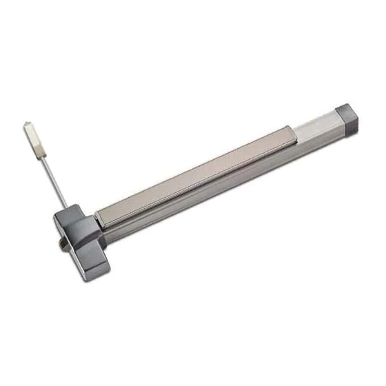
INSTALLING 6EWS TRIM
WITH 6200 SERIES
EXIT DEVICE
1. INSTALL 6EWS
EXIT DEVICE TRIM
Insert trim on outside of door. Feed
wire through door and keep taught as
trim is put in place against the door.
3. FASTEN TO DOOR
Install and secure exit device to trim through
bolts with (4) included pan head screws using
#2 Phillips screwdriver.
2754 Creek Hill Road | Leola, PA 17540 | 800.441.9692 | www.pdqlocks.com
2. INSTALL EXIT DEVICE
Remove chassis cover from exit device by
removing (4) flat head screws. Install device
without chassis cover on to face of door while
feeding wire harness through hole in exit device
chassis.
INSTRUCTION #629905 | REV 0 | 1/30/2017
Advertisement
Table of Contents

Related Manuals for PDQ 6200 Series


Summary of Contents for PDQ 6200 Series
- Page 1 INSTALLING 6EWS TRIM WITH 6200 SERIES EXIT DEVICE 1. INSTALL 6EWS EXIT DEVICE TRIM Insert trim on outside of door. Feed wire through door and keep taught as trim is put in place against the door. 2. INSTALL EXIT DEVICE Remove chassis cover from exit device by removing (4) flat head screws.
- Page 2 INSTALLING 6EWS TRIM WITH 6200 SERIES EXIT DEVICE 4. CONNECT WIRE Attach wire harness connectors as shown. Push excess wire into door cavity. 5. INSTALL CHASSIS COVER Re-install chassis cover using (4) flat head screws. 2754 Creek Hill Road | Leola, PA 17540 | 800.441.9692 | www.pdqlocks.com...
- Page 3 INSTALLING / REPLACING 6EWS BATTERIES Batteries are located in exit device rail. For new installations, connect wiring harness plug to exit device trim before installing batteries. 1. REMOVE END CAP Remove exit device end cap and set aside 2. LOCATING BATTERIES Remove exit device rail insert by sliding toward hinge side of door.
- Page 4 INSTALLING / REPLACING CYLINDER It is necessary to partially disassemble the trim to replace the cylinder. Take care to not damage the wire harness. Begin with trim laying face down on table or other flat surface. 1. REMOVE PIN Remove cotter pin from drive spindle. Factory position is in bottom hole and is set of 1-3/4”...
- Page 5 HANDING TRIM 6EWS trim is easily field handed. It is simply necessary to point the lever in the correct direction and insert the 8mm drive spindle. 1. SET HANDING Rotate lever to correct location for handing of door. 2. INSERT SPINDLE Insert square 8mm spindle until c-clip is against face of hub.
- Page 6 2754 Creek Hill Road | Leola, PA 17540 | 800.441.9692 | www.pdqlocks.com...
Need help?
Do you have a question about the 6200 Series and is the answer not in the manual?
Questions and answers