Table of Contents
Advertisement
Quick Links
Advertisement
Table of Contents

Related Manuals for IEI Technology PUZZLE-IN004 Series


Summary of Contents for IEI Technology PUZZLE-IN004 Series
- Page 1 PUZZLE-IN004 MODEL: PUZZLE-IN004 1U Network Appliance with Intel® Xeon® D-2100 Series Processor, Eight DDR4, Eight GbE Ports, Four 10GbE SFP+, One PCIe x8 Slot, Two M.2, PCIe Mini, Redundant PSU, Rack Mount, and RoHS Compliant User Manual Page i Rev. 1.00 – June 9, 2020...
- Page 2 PUZZLE-IN004 Revision Date Version Changes June 9, 2020 1.00 Initial release Page ii...
- Page 3 PUZZLE-IN004 Copyright COPYRIGHT NOTICE The information in this document is subject to change without prior notice in order to improve reliability, design and function and does not represent a commitment on the part of the manufacturer. In no event will the manufacturer be liable for direct, indirect, special, incidental, or consequential damages arising out of the use or inability to use the product or documentation, even if advised of the possibility of such damages.
- Page 4 PUZZLE-IN004 Manual Conventions WARNING Warnings appear where overlooked details may cause damage to the equipment or result in personal injury. Warnings should be taken seriously. CAUTION Cautionary messages should be heeded to help reduce the chance of losing data or damaging the product. NOTE These messages inform the reader of essential but non-critical information.
-
Page 5: Table Of Contents
PUZZLE-IN004 Table of Contents 1 INTRODUCTION ......................1 1.1 O ........................2 VERVIEW 1.2 F ........................2 EATURES 1.3 M ....................3 ODEL ARIATIONS 1.4 F ......................4 RONT ANEL 1.5 R ....................... 4 ANEL 1.6 T ..................5 ECHNICAL PECIFICATIONS 1.7 D ....................... - Page 6 PUZZLE-IN004 3.10 P ..................32 OWER ROCEDURE 3.11 R ..................33 ESOURCE OWNLOAD 3.12 M ....................... 34 AINTENANCE 3.12.1 Power Supply Unit Replacement ..............35 3.12.2 SSD Replacement ................... 36 3.12.3 Jumper Settings ....................38 3.12.3.1 AT/ATX Power Mode Setting ..............38 3.12.3.2 Clear CMOS ....................
- Page 7 PUZZLE-IN004 4.8 S & E ......................65 5 INTERFACE CONNECTORS ................... 66 5.1 P ..............67 ERIPHERAL NTERFACE ONNECTORS 5.2 I ..............68 NTERNAL ERIPHERAL ONNECTORS 5.2.1 ATX 12V Power Connector (CPU12V1) ............69 5.2.2 ATX Power Connector (ATX1) ................. 69 5.2.3 ATX Power SMBus Connector (J_ATX1) ............
- Page 8 PUZZLE-IN004 C.1 PEI B ..................... 89 ODES C.2 DXE B ....................89 ODES D HAZARDOUS MATERIALS DISCLOSURE ............90 D.1 R HS II D (2015/863/EU) ............... 91 IRECTIVE D.2 C HS ......................92 HINA Page viii...
- Page 9 PUZZLE-IN004 List of Figures Figure 1-1: PUZZLE-IN004 Series ....................2 Figure 1-2: PUZZLE-IN004 Front Panel ..................4 Figure 1-3: PUZZLE-IN004 Rear Panel ..................4 Figure 1-4: Physical Dimensions (millimeters) ................7 Figure 3-1: Top Cover Removal ....................14 Figure 3-2: DIMM Slot Locations ....................15 Figure 3-3: Expansion Slot Module Retention Screws .............
- Page 10 PUZZLE-IN004 List of Tables Table 1-1: PUZZLE-IN004 Model Variations ................. 3 Table 1-2: Technical Specifications ....................6 Table 3-1: 1GbE Port Pinouts ...................... 26 Table 3-2: RJ-45 1GbE Connector LEDs ..................26 Table 3-3: 10GbE Port Pinouts ....................27 Table 3-4: RJ-45 Serial Port Pinouts ................... 28 Table 3-5: Clear BIOS Jumper Settings ..................
-
Page 11: Introduction
PUZZLE-IN004 Chapter Introduction Page 1... -
Page 12: Overview
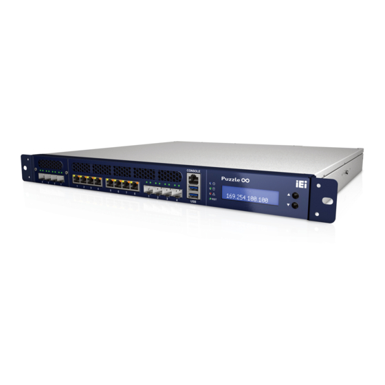
PUZZLE-IN004 1.1 Overview Figure 1-1: PUZZLE-IN004 Series ® ® The PUZZLE-IN004 is a 1 U network appliance series powered by Intel Xeon D-2100 series processor. It is optimized to host VNFs (Virtual Network Functions) and is ideal for SD-WAN. The PUZZLE-IN004 supports eight copper GbE ports and four 10GbE SFP+ connections for high-speed network applications. -
Page 13: Model Variations
PUZZLE-IN004 Supports one USB 3.2 Gen 1 (5Gb/s) port and one USB 2.0 port 1U chassis for rack mounting RoHS compliant 1.3 Model Variations The model variations of the PUZZLE-IN004 are listed below. PUZZLE-IN004 DDR4 Memory ® ®... -
Page 14: Front Panel
PUZZLE-IN004 1.4 Front Panel The overview of the front panel is shown in Figure 1-2. Figure 1-2: PUZZLE-IN004 Front Panel The states of the LED indicators located on the front panel are listed below. The system is turned off. Power LED Blue The system is turned on. -
Page 15: Technical Specifications
PUZZLE-IN004 1.6 Technical Specifications The PUZZLE-IN004 technical specifications are listed in Table 1-2. System Form Factor ® ® CPU (SoC) Intel Xeon D-2100 series processor ® ® XD1: Intel Xeon D-2145NT ® ® XD2: Intel Xeon D-2146NT ® ® XD3: Intel Xeon D-2166NT ®... -
Page 16: Table 1-2: Technical Specifications
PUZZLE-IN004 2 x M.2 2280 M-key slots (PCIe x4) I/O and Indicators Console 1 x RJ-45 RS-232 1 x USB 3.2 Gen 1 (5 Gb/s) port (external, Type A) 1 x USB 2.0 port (external, Type A) Digital I/O 4-bit input, 4-bit output (internal 10-pin header) Indicator LCM (with two control buttons) Power status (blue) -
Page 17: Dimensions
PUZZLE-IN004 1.7 Dimensions The physical dimensions are shown below: Figure 1-4: Physical Dimensions (millimeters) Page 7... -
Page 18: Unpacking
PUZZLE-IN004 Chapter Unpacking Page 8... -
Page 19: Anti-Static Precautions
PUZZLE-IN004 2.1 Anti-static Precautions WARNING: Failure to take ESD precautions during installation may result in permanent damage to the PUZZLE-IN004 and severe injury to the user. Electrostatic discharge (ESD) can cause serious damage to electronic components, including the PUZZLE-IN004. Dry climates are especially susceptible to ESD. It is therefore critical that whenever the PUZZLE-IN004 or any other electrical component is handled, the following anti-static precautions are strictly adhered to. -
Page 20: Packing List
PUZZLE-IN004 2.3 Packing List NOTE: If some of the components listed in the checklist below are missing, please do not proceed with the installation. Contact the IEI reseller or vendor you purchased the PUZZLE-IN004 from or contact an IEI sales representative directly. -
Page 21: Optional Items
PUZZLE-IN004 2.4 Optional Items The following table lists the optional items that can be purchased separately. Optional Item Image Sliding rails (P/N: RAIL-B02) USB to console cable (P/N: 32013-004000-100-RS) RS-232 to console cable (P/N: 32005-005100-100-RS) Page 11... -
Page 22: Installation
PUZZLE-IN004 Chapter Installation Page 12... -
Page 23: Installation Precautions
PUZZLE-IN004 3.1 Installation Precautions During installation, be aware of the precautions below: Read the user manual: The user manual provides a complete description of the PUZZLE-IN004, installation instructions and configuration options. DANGER! Disconnect Power: Power to the PUZZLE-IN004 must be ... -
Page 24: Dimm Installation
PUZZLE-IN004 Figure 3-1: Top Cover Removal 3.3 DIMM Installation CAUTION: 1. Be sure to install the memory modules in the blue slots first. 2. For multi-channel configuration, always install the identical memory modules that feature the same capacity, timings, voltage, number of ranks and the same brand. -
Page 25: Pcie Expansion Card Installation
PUZZLE-IN004 Figure 3-2: DIMM Slot Locations Step 3: Open the DIMM socket handles. Open the two handles outwards as far as they can. Step 4: Align the DIMM so the notch on the memory lines up with the notch on the memory socket. -
Page 26: Figure 3-3: Expansion Slot Module Retention Screws
PUZZLE-IN004 Step 2: Remove the four expansion slot module retention screws indicated below. Figure 3-3: Expansion Slot Module Retention Screws Page 16... -
Page 27: Figure 3-4: Disconnect The Expansion Slot Module
PUZZLE-IN004 Step 3: Push the expansion slot module with strength to disconnect the module from the edge connector of the motherboard. Figure 3-4: Disconnect the Expansion Slot Module Step 4: Remove the blank bracket panel that aligns with the PCIe slot for installing the expansion card. -
Page 28: Figure 3-6: Pcie Expansion Card Installation
PUZZLE-IN004 Step 5: Align the expansion card to the PCIe slot. Press gently, but firmly, to seat the expansion card correctly in the slot. Install the bracket screw(s) to secure the card to the expansion slot module. Figure 3-6: PCIe Expansion Card Installation Step 6: Place the expansion slot module back to the original position by hooking the slotted hole into the positioning stud in the chassis (Figure 3-7 A). -
Page 29: Figure 3-7: Expansion Slot Module Installation
PUZZLE-IN004 Figure 3-7: Expansion Slot Module Installation Step 7: Secure the expansion slot module with the four retention screws previously removed. Page 19... -
Page 30: Iei Networking Module Installation
PUZZLE-IN004 3.5 IEI Networking Module Installation The PUZZLE-IN004 allows installation of one IEI PulM networking module. The slot supports 8 lanes from CPU (1 PCIe x8 or 2 PCIe x4). For pinouts of the slot, refer to Section 5.2.18. To install a networking module, please follow the steps below. Step 1: Remove the two Torx (star) screws indicated below to remove the slot cover. -
Page 31: Bypass Configuration In Bios
PUZZLE-IN004 3.5.1 Bypass Configuration in BIOS Some PulM modules support bypass. To enable/disable bypass function, configure the BIOS menu of the PUZZLE-IN004 as described below. Step 1: Boot the system to BIOS. Go to Advanced NETWORK Configuration (Bypass Setting). Aptio Setup Utility –... -
Page 32: Module Installation
PUZZLE-IN004 Step 3: Configure the Power_ON ByPass Mode and the Power_OFF ByPass Mode BIOS options to enable/disable bypass function of the installed PulM module. PUZZLE-IN004 BIOS Setting Power_ON ByPass Mode Power_OFF ByPass Mode Disabled Enabled Disabled Enabled PulM Bypass Bypass is disabled Bypass is enabled Bypass is disabled Bypass is enabled... -
Page 33: Pcie Mini Card Installation
PUZZLE-IN004 Step 3: Locate the M.2 slots on the motherboard. Step 4: Remove the on-board retention screw. Step 5: Line up the notch on the module with the notch on the slot. Slide the M.2 module into the socket at an angle of about 20º. Step 6: Push the M.2 module down and secure it with the previously removed retention screw. -
Page 34: Half-Size Pcie Mini Card Installation
PUZZLE-IN004 Figure 3-11: PCIe Mini Slot Location Step 3: To avoid interference of the board circuit, remove the retention screw and standoff for a half-size PCIe Mini card. Step 4: Remove the pre-installed retention screw from the standoff for a full-size PCIe Mini card. -
Page 35: External Interface Connection
PUZZLE-IN004 Step 2: Line up the notch on the card with the notch on the slot. Slide the PCIe Mini card into the socket at an angle of about 20º. Step 3: Secure the half-size PCIe Mini card with the retention screw previously removed. -
Page 36: Lan Connection - 1Gbe
PUZZLE-IN004 3.8.1 LAN Connection - 1GbE The four 1GbE LAN connectors on the front panel allow connection to an external network. The pinouts of the LAN connectors are listed below. Description Description MDIA3- MDIA1+ MDIA3+ MDIA2+ MDIA2- MDIA0- MDIA1- MDIA0+ Table 3-1: 1GbE Port Pinouts Figure 3-12: RJ-45 1GbE Connector The RJ-45 Ethernet connector has two status LEDs, one yellow and one green/orange. -
Page 37: Lan Connection - 10Gbe Sfp
PUZZLE-IN004 3.8.2 LAN Connection - 10GbE SFP+ The four 10GbE SFP+ connectors on the front panel allow transfer rate of up to 10 gigabits per second. The pinouts of the 10GbE LAN connectors are listed below. Description Description SFP+_TX_FAULT SFP+_RX- SFP+_TX_DISABLE SFP+_RX+ SFP+_SDA... -
Page 38: Console Connection
PUZZLE-IN004 3.8.3 Console Connection The PUZZLE-IN004 has one RJ-45 serial device connector on the front panel. The RJ-45 connector for the serial port can be identified easily as the RJ-45 for the network has two LEDs on the port, while the connectors for the serial cables don’t. The pinouts of the serial port are listed below. - Page 39 PUZZLE-IN004 Step 3: Open a serial console application, PuTTY, as an example. Step 4: Set the speed of the serial connection to “115200”, and choose “Serial” for Connection Type. Step 5: Click “Open” on PuTTY. Page 29...
- Page 40 PUZZLE-IN004 Step 6: Enter the following command: sudo vi /lib/systemd/system/ttyS0.service Step 7: Ensure the information shown match the followings: [Unit] Description=Serial Console Service [Service] ExecStart=/sbin/getty -L 115200 ttyS0 vt102 Restart=always [Install] WantedBy=multi-user.target Step 8: Run the following commands one by one: sudo systemctl daemon-reload sudo systemctl enable ttyS0 sudo systemctl start ttyS0...
-
Page 41: Rack Mount
PUZZLE-IN004 3.9 Rack Mount The PUZZLE-IN004 is shipped with two rack mount brackets that could be used to secure the system to the rack after mounting it with the optional sliding rails. To install the PUZZLE-IN004 into a rack, please follow the steps below. WARNING: The provided rack mount brackets must be used with sliding rails. -
Page 42: Power-On Procedure
PUZZLE-IN004 3.10 Power-On Procedure WARNING: Make sure a power supply with the correct input voltage is being fed into the system. Incorrect voltages applied to the system may cause damage to the internal electronic components and may also cause injury to the user. To power-on the PUZZLE-IN004 please follow the steps below: Step 1: Connect the power source to both of the power inlets on the rear panel. -
Page 43: Resource Download
PUZZLE-IN004 NOTE: Connecting only one power supply will trigger the beep sound. If redundant power usage is not necessary for the application, press the PSU beep off button to disable the beep sound. 3.11 Resource Download All the resources for the PUZZLE-IN004 are available on IEI Resource Download Center (https://download.ieiworld.com). -
Page 44: Maintenance
PUZZLE-IN004 3.12 Maintenance WARNING: The following instructions should only be performed by an authorized and trained technician. Before starting, please ensure that you turn off the PUZZLE-IN004, disconnect the power cords, network cable(s), and also remove any other device/cable that is attached to the server. Take Anti-Static precautions whenever maintenance is being carried out on the system components. -
Page 45: Power Supply Unit Replacement
PUZZLE-IN004 3.12.1 Power Supply Unit Replacement To replace a failed power supply unit, please follow the steps below. Step 1: Turn off the PUZZLE-IN004. Disconnect the power cords, network cable(s), and any other connectors or cables from the PUZZLE-IN004. Step 2: Firmly press and hold the black button on back of PSU downwards. -
Page 46: Ssd Replacement
PUZZLE-IN004 3.12.2 SSD Replacement To replace a failed SSD, please follow the steps below. Step 1: Remove the top cover from the PUZZLE-IN004. Please follow the instruction described in Section 3.2. Step 2: Remove the SSD bracket from the system. To do this, remove the three retention screws indicated below and disconnect the SATA connector module from the motherboard. -
Page 47: Figure 3-17: Remove Ssd From The Bracket
PUZZLE-IN004 Figure 3-17: Remove SSD from the Bracket Step 4: Insert a new SSD into the bracket until the SSD is properly connected to the SATA connector. Secure the SSD with the four retention screws removed previously. Step 5: Re-connect the SATA connector module to the motherboard. Make sure the two positioning studs on the chassis go through the two small holes on the SSD bracket (Figure 3-18). -
Page 48: Jumper Settings
PUZZLE-IN004 3.12.3 Jumper Settings To configure the jumper settings, please follow the steps below. Step 1: Remove the top cover. See Section 3.2. Step 2: Locate the jumper/switch on the embedded motherboard. Step 3: Make the jumper settings in accordance with the settings described and defined in the following sections. -
Page 49: Clear Cmos
PUZZLE-IN004 3.12.3.2 Clear CMOS If the PUZZLE-IN004 fails to boot due to improper BIOS settings, the clear CMOS jumper clears the CMOS data and resets the system BIOS information. To do this, short the jumper for 3 seconds or more, then remove the jumper clip. Setting Description Open... -
Page 50: Flash Descriptor Security Override Jumper
PUZZLE-IN004 3.12.4 Flash Descriptor Security Override Jumper The Flash Descriptor Security Override jumper (J_ME1) allows to enable or disable the ME firmware update. Setting Description Open Disabled (default) Short Enabled Table 3-6: Flash Descriptor Security Override Jumper Settings Figure 3-21: Flash Descriptor Security Override Jumper Location To update the ME firmware, please follow the steps below. -
Page 51: Bios
PUZZLE-IN004 Chapter BIOS Page 41... -
Page 52: Introduction
PUZZLE-IN004 4.1 Introduction The BIOS is programmed onto the BIOS chip. The BIOS setup program allows changes to certain system settings. This chapter outlines the options that can be changed. NOTE: Some of the BIOS options may vary throughout the life cycle of the product and are subject to change without prior notice. -
Page 53: Getting Help
PUZZLE-IN004 Function Decrease the numeric value or make changes Esc key Main Menu – Quit and not save changes into CMOS Status Page Setup Menu and Option Page Setup Menu -- Exit current page and return to Main Menu F1 key General help, only for Status Page Setup Menu and Option Page Setup Menu F2 key... -
Page 54: Main
PUZZLE-IN004 The following sections completely describe the configuration options found in the menu items at the top of the BIOS screen and listed above. 4.2 Main The Main BIOS menu (BIOS Menu 1) appears when the BIOS Setup program is entered. The Main menu gives an overview of the basic system information. -
Page 55: Advanced
PUZZLE-IN004 System Time [xx:xx:xx] Use the System Time option to set the system time. Manually enter the hours, minutes and seconds. 4.3 Advanced Use the Advanced menu (BIOS Menu 2) to configure the CPU and peripheral devices through the following sub-menus: WARNING! Setting the wrong values in the sections below may cause the system to malfunction. -
Page 56: Trusted Computing
PUZZLE-IN004 Restore AC Power Loss [Last State] Use the Restore AC Power Loss BIOS option to specify what state the system returns to if there is a sudden loss of power to the system. Power Off The system remains turned off ... -
Page 57: Iwdd H/W Monitor
PUZZLE-IN004 Security Device Support [Enable] Use the Security Device Support option to configure support for the TPM. Disable TPM support is disabled. Enable TPM support is enabled. EFAULT Pending Operation [None] Use the Pending Operation option to schedule an operation for the security device. ... -
Page 58: Smart Fan Mode Configuration
PUZZLE-IN004 PC Health Status The following system parameters and values are shown. The system parameters that are monitored are: Temperatures: CPU temperature System temperature Fan Speeds: CPU Fan Speed System Fan Speed Voltages: CPU_CORE +12V +5VSB +3.3V +3.3VSB 4.3.2.1 Smart Fan Mode Configuration... - Page 59 PUZZLE-IN004 Aptio Setup Utility – Copyright (C) 2019 American Megatrends, Inc. Advanced Smart Fan Mode Configuration Smart Fan Mode Select CPU_FAN1 Smart Fan Control [Auto Mode] Auto mode fan start temperature --------------------- Auto mode fan off temperature : Select Screen Auto mode fan start PWM ↑...
-
Page 60: It8528 Super Io Configuration
PUZZLE-IN004 Auto mode fan start PWM Use the Auto mode fan start PWM option to set the PWM start value. Use the + or – key to change the value or enter a decimal number between 1 and 100. Auto mode fan slope PWM ... -
Page 61: Serial Port 1 Configuration
PUZZLE-IN004 4.3.3.1 Serial Port 1 Configuration Use the Serial Port 1 Configuration menu (BIOS Menu 7) to configure the serial port n. Aptio Setup Utility – Copyright (C) 2019 American Megatrends, Inc. Advanced Serial Port n Configuration Enable or Disable Serial Port (COM) Serial Port [Enabled]... - Page 62 PUZZLE-IN004 Aptio Setup Utility – Copyright (C) 2019 American Megatrends, Inc. Advanced Console Redirection COM0 Console Redirection [Enabled] Enable or Disable > Console Redirection Settings Legacy Console Redirection -------------------- > Legacy Console Redirection Settings : Select Screen ↑ ↓: Select Item Enter: Select +/-: Change Opt.
- Page 63 PUZZLE-IN004 Bits per second [115200] Use the Bits per second option to specify the serial port transmission speed. The speed must match the other side. Long or noisy lines may require lower speeds. 9600 Sets the serial port transmission speed at 9600. ...
-
Page 64: Legacy Console Redirection Settings
PUZZLE-IN004 Stop Bits [1] Use the Stop Bits option to specify the number of stop bits used to indicate the end of a serial data packet. Communication with slow devices may require more than 1 stop bit. Sets the number of stop bits at 1. EFAULT ... -
Page 65: Nvme Configuration
PUZZLE-IN004 4.3.5 NVMe Configuration Use the NVMe Configuration menu (BIOS Menu 10) to change and/or set the configuration of the NVMe devices installed in the system. Aptio Setup Utility – Copyright (C) 2019 American Megatrends, Inc. Advanced NVMe Configuration No NVME Device Found --------------------- : Select Screen ↑... -
Page 66: Network Configuration (Bypass Setting)
PUZZLE-IN004 4.3.6 Network Configuration (Bypass Setting) Use the NETWORK Configuration (ByPass Setting) menu (BIOS Menu 10) to configure the bypass setting of the PulM module installed in the system. Aptio Setup Utility – Copyright (C) 2019 American Megatrends, Inc. Advanced Network ByPass Settings Select AC power state when power is re-applied after a... -
Page 67: Platform Configuration
PUZZLE-IN004 4.4 Platform Configuration Use the Platform Configuration menu (BIOS Menu 12) to configure the platform parameters. Aptio Setup Utility – Copyright (C) 2019 American Megatrends, Inc. Main Advanced Platform Configuration Socket Configuration Security Boot > PCH sSATA Configuration sSATA devices and settings --------------------- : Select Screen... - Page 68 PUZZLE-IN004 SATA Controller [Enable] Use the SATA Controller option to enable or disable the SATA device. Enable Enables the SATA device. EFAULT Disable Disables the SATA device. Configure sSATA as [AHCI] Use the Configure sSATA as option to configure how the SATA controller(s) operate. ...
-
Page 69: Socket Configuration
PUZZLE-IN004 4.5 Socket Configuration Use the Socket Configuration menu (BIOS Menu 14) to configure the socket parameters. Aptio Setup Utility – Copyright (C) 2019 American Megatrends, Inc. Main Advanced Platform Configuration Socket Configuration Security Boot Intel® VT for Directed [Enable] Enable/Disable Intel®... -
Page 70: Processor Configuration
PUZZLE-IN004 4.5.1 Processor Configuration Use the Processor Configuration menu (BIOS Menu 15) to view detailed CPU specifications or enable the Intel Virtualization Technology. Aptio Setup Utility – Copyright (C) 2019 American Megatrends, Inc. Socket Configuration Processor Configuration Enable/disable CPU -------------------------------------------------- Virtualization Processor BSP Revision 50654 –... -
Page 71: Memory Topology
PUZZLE-IN004 4.5.2 Memory Topology Use the Memory Topology submenu (BIOS Menu 16) to display the memory information. Aptio Setup Utility – Copyright (C) 2019 American Megatrends, Inc. Socket Configuration ----------------------------------------------- Socket0.ChA.Dimm0: DIMM is Present. DIMM St... Socket0.ChB.Dimm0: DIMM is Present. DIMM St... --------------------- : Select Screen ↑... -
Page 72: Security
PUZZLE-IN004 4.6 Security Use the Security menu (BIOS Menu 17) to set system and user passwords. Aptio Setup Utility – Copyright (C) 2019 American Megatrends, Inc. Main Advanced Platform Configuration Socket Configuration Security Boot Password Description Set Administrator Password If ONLY the Administrator’s password is set, then this only limits access to Setup and is only asked for when entering Setup. -
Page 73: Boot
PUZZLE-IN004 4.7 Boot Use the Boot menu (BIOS Menu 18) to configure system boot options. Aptio Setup Utility – Copyright (C) 2019 American Megatrends, Inc. Main Advanced Platform Configuration Socket Configuration Security Boot Boot Configuration Select the keyboard Bootup NumLock State [On] NumLock state Launch PXE OpROM... - Page 74 PUZZLE-IN004 Launch PXE OpROM [Disabled] Use the Launch PXE OpROM option to enable or disable boot option for legacy network devices. Disabled Ignore all PXE Option ROMs EFAULT Enabled Load PXE Option ROMs. UEFI Boot [Disabled] Use the UEFI Boot option to enable or disable to boot from the UEFI devices.
-
Page 75: Save & Exit
PUZZLE-IN004 4.8 Save & Exit Use the Safe & Exit menu (BIOS Menu 19) to load default BIOS values, optimal failsafe values and to save configuration changes. Aptio Setup Utility – Copyright (C) 2019 American Megatrends, Inc. Save & Exit Save Changes and Reset Exit the system after Discard Changes and Reset... -
Page 76: Interface Connectors
PUZZLE-IN004 Chapter Interface Connectors Page 66... -
Page 77: Peripheral Interface Connectors
PUZZLE-IN004 5.1 Peripheral Interface Connectors The connector locations of the PUZZLE-IN004’s motherboard are shown below. The connector pinouts for these connectors are listed in the following sections. Page 67... -
Page 78: Internal Peripheral Connectors
PUZZLE-IN004 5.2 Internal Peripheral Connectors Internal peripheral connectors on the motherboard and are only accessible when the motherboard is outside of the chassis. The table below shows a list of the connectors on the motherboard. Pinouts of these connectors can be found in the following sections. Connector Type Label... -
Page 79: Atx 12V Power Connector (Cpu12V1)
PUZZLE-IN004 5.2.1 ATX 12V Power Connector (CPU12V1) Description Description +12 V +12 V +12 V +12 V Table 5-1: ATX 12V Power Connector (CPU12V1) Pinouts 5.2.2 ATX Power Connector (ATX1) Description Description +3.3 V +3.3 V +3.3 V -12 V +5 V PS-ON +5 V... -
Page 80: Atx Power Smbus Connector (J_Atx1)
PUZZLE-IN004 5.2.3 ATX Power SMBus Connector (J_ATX1) PIN NO. DESCRIPTION ATX_SMCLK ATX_SMDAT Table 5-3: ATX Power SMBus Connector (J_ATX1) Pinouts 5.2.4 Debug Port (DBG_PORT1) PIN NO. DESCRIPTION PIN NO. DESCRIPTION LPC_AD1 VCC3V LPC_AD0 FRAME SERIRQ RESET LPC_AD3 LPC_AD2 Table 5-4: Debug Port (DBG_PORT1) Pinouts 5.2.5 Chassis Intrusion Connector (CHASSIS1) PIN NO. -
Page 81: Cpld Programmer Connector (J_Cpld1)
PUZZLE-IN004 5.2.6 CPLD Programmer Connector (J_CPLD1) PIN NO. DESCRIPTION PIN NO. DESCRIPTION VCC3 Table 5-6: CPLD Programmer Connector (J_CPLD1) Pinouts 5.2.7 DIO Connector (DIO1) PIN NO. DESCRIPTION PIN NO. DESCRIPTION VCC5 Output 3 Output 2 Output 1 Output 0 ... -
Page 82: Fan Connectors (Cpu_Fan1/2/3 & Sys_Fan1)
PUZZLE-IN004 5.2.9 Fan Connectors (CPU_FAN1/2/3 & SYS_FAN1) PIN NO. DESCRIPTION +12V FANIO Table 5-9: Fan Connectors (CPU_FAN1/2/3 & SYS_FAN1) Pinouts 5.2.10 Front Panel Connector (F_PANEL1) Function PIN DESCRIPTION Function PIN DESCRIPTION Power LED+ SPKR+ PWR_LED Power LED- Speaker Power Button+ SPKR- PWR_BTN Power Button+... -
Page 83: Pcie Mini Card Slot (Mini-Pcie1)
PUZZLE-IN004 5.2.12 PCIe Mini Card Slot (MINI-PCIE1) PIN NO. DESCRIPTION PIN NO. DESCRIPTION WAKE VCC3 VCC1.5 SIM_VCC SIM_CIO SIM_CLK SIM_RST SIM_VPP VCC3 VCC1.5 MINIPCIE_SDA MINIPCIE_SCL USB_DATA_N USB_DATA_P VCC3 VCC3 VCC1.5 VCC3 Table 5-12: PCIe Mini Card Slot (MINI-PCIE1) Pinouts Page 73... -
Page 84: Power Button Connector (Pwr_Btn1)
PUZZLE-IN004 5.2.13 Power Button Connector (PWR_BTN1) PIN NO. DESCRIPTION PWR_BTN Table 5-13: Power Button Connector (PWR_BTN1) Pinouts 5.2.14 SATA Connector (SATA1) PIN NO. DESCRIPTION PIN NO. DESCRIPTION VCC12 VCC12 VCC12 VCC12 VCC12 SATA01_TXN VCC5 SATA01_TXP VCC5 SATA01_RXN VCC3 SATA01_RXP VCC5 VCC3 VCC5 VCC3... -
Page 85: Spi Flash Connector (J_Spi1)
PUZZLE-IN004 5.2.15 SPI Flash Connector (J_SPI1) PIN NO. DESCRIPTION PIN NO. DESCRIPTION VCC3 MOSI MISO Table 5-15: SPI Flash Connector (J_SPI1) Pinouts 5.2.16 SPI Flash Connector - EC (J_EC1) PIN NO. DESCRIPTION PIN NO. DESCRIPTION VCC3 MOSI MISO Table 5-16: SPI Flash Connector (J_EC1) Pinouts 5.2.17 USB DOM Connector (USB_DOM1) PIN NO. - Page 86 PUZZLE-IN004 SMCLK SMDAT +3.3v +3.3v 3.3Vaux +3.3v WAKE# PWRGD REFCLK+ HSOp(0) REFCLK- HSOn(0) HSIp(0) RLYCTL1* HSIn(0) HSOp(1) LANID1** HSOn(1) HSIp(1) HSIn(1) HSOp(2) HSOn(2) HSIp(2) HSIn(2) HSOp(3) HSOn(3) HSIp(3) RLYCTL2* HSIn(3) LANID2** HSOp(4) HSOn(4) HSIp(4) HSIn(4) Page 76...
-
Page 87: Table 5-18: Iei Networking Module Slot Pinouts
PUZZLE-IN004 HSOp(5) HSOn(5) HSIp(5) HSIn(5) HSOp(6) HSOn(6) HSIp(6) HSIn(6) HSOp(7) HSOn(7) HSIp(7) HSIn(7) *PIN B17 & B30 is assigned to Relay control signal; it is only active when inserting a specific LAN module that supports LAN bypass function. **PIN A19 & A32 is identification of PCIe Link configuration. See Table 5-19 for PCIe Link configuration. -
Page 88: A Regulatory Compliance
PUZZLE-IN004 Appendix Regulatory Compliance Page 78... - Page 89 PUZZLE-IN004 DECLARATION OF CONFORMITY This equipment is in conformity with the following EU directives: EMC Directive 2014/30/EU Low-Voltage Directive 2014/35/EU RoHS II Directive 2015/863/EU If the user modifies and/or install other devices in the equipment, the CE conformity declaration may no longer apply.
- Page 90 PUZZLE-IN004 Español [Spanish] IEI Integration Corp declara que el equipo cumple con los requisitos esenciales y cualesquiera otras disposiciones aplicables o exigibles de la Directiva 1999/5/CE. Ελληνική [Greek] IEI Integration Corp ΔΗΛΩΝΕΙ ΟΤΙ ΕΞΟΠΛΙΣΜΟΣ ΣΥΜΜΟΡΦΩΝΕΤΑΙ ΠΡΟΣ ΤΙΣ ΟΥΣΙΩΔΕΙΣ ΑΠΑΙΤΗΣΕΙΣ ΚΑΙ ΤΙΣ ΛΟΙΠΕΣ ΣΧΕΤΙΚΕΣ ΔΙΑΤΑΞΕΙΣ ΤΗΣ ΟΔΗΓΙΑΣ 1999/5/ΕΚ.
- Page 91 PUZZLE-IN004 Româna [Romanian] IEI Integration Corp declară că acest echipament este in conformitate cu cerinţele esenţiale şi cu celelalte prevederi relevante ale Directivei 1999/5/CE. Slovensko [Slovenian] IEI Integration Corp izjavlja, da je ta opreme v skladu z bistvenimi zahtevami in ostalimi relevantnimi določili direktive 1999/5/ES.
- Page 92 PUZZLE-IN004 FCC WARNING This equipment complies with Part 15 of the FCC Rules. Operation is subject to the following two conditions: This device may not cause harmful interference, and This device must accept any interference received, including interference that ...
-
Page 93: B Safety Precautions
PUZZLE-IN004 Appendix Safety Precautions Page 83... -
Page 94: Safety Precautions
PUZZLE-IN004 B.1 Safety Precautions WARNING: The precautions outlined in this appendix should be strictly followed. Failure to follow these precautions may result in permanent damage to the PUZZLE-IN004. Please follow the safety precautions outlined in the sections that follow: B.1.1 General Safety Precautions Please ensure the following safety precautions are adhered to at all times. -
Page 95: Product Disposal
PUZZLE-IN004 Electrostatic discharge (ESD) can cause serious damage to electronic components, including the PUZZLE-IN004. Dry climates are especially susceptible to ESD. It is therefore critical that whenever the PUZZLE-IN004 is opened and any of the electrical components are handled, the following anti-static precautions are strictly adhered to. Wear an anti-static wristband: Wearing a simple anti-static wristband can ... -
Page 96: Maintenance And Cleaning Precautions
PUZZLE-IN004 the guidance of your local authority, or ask the shop where you purchased the product. The mark on electrical and electronic products only applies to the current European Union Member States. Please follow the national guidelines for electrical and electronic product disposal. B.2 Maintenance and Cleaning Precautions When maintaining or cleaning the PUZZLE-IN004, please follow the guidelines below. - Page 97 PUZZLE-IN004 Vacuum cleaner – Using a vacuum specifically designed for computers is one of the best methods of cleaning the PUZZLE-IN004. Dust and dirt can restrict the airflow in the PUZZLE-IN004 and cause its circuitry to corrode. Swabs - Swaps moistened with rubbing alcohol or water are excellent tools ...
-
Page 98: C Error Beep Code
PUZZLE-IN004 Appendix Error Beep Code Page 88... -
Page 99: Pei Beep Codes
PUZZLE-IN004 C.1 PEI Beep Codes Number of Beeps Description Memory not Installed Memory was installed twice (InstallPeiMemory routine in PEI Core called twice) Recovery started DXEIPL was not found DXE Core Firmware Volume was not found Recovery failed S3 Resume failed Reset PPI is not available C.2 DXE Beep Codes Number of Beeps... -
Page 100: D Hazardous Materials Disclosure
PUZZLE-IN004 Appendix Hazardous Materials Disclosure Page 90... -
Page 101: Rohs Ii Directive (2015/863/Eu)
PUZZLE-IN004 D.1 RoHS II Directive (2015/863/EU) The details provided in this appendix are to ensure that the product is compliant with the RoHS II Directive (2015/863/EU). The table below acknowledges the presences of small quantities of certain substances in the product, and is applicable to RoHS II Directive (2015/863/EU). -
Page 102: China Rohs
PUZZLE-IN004 D.2 China RoHS 此附件旨在确保本产品符合中国 RoHS 标准。以下表格标示此产品中某有毒物质的含量符 合中国 RoHS 标准规定的限量要求。 本产品上会附有”环境友好使用期限”的标签,此期限是估算这些物质”不会有泄漏或突变”的 年限。本产品可能包含有较短的环境友好使用期限的可替换元件,像是电池或灯管,这些 元件将会单独标示出来。 部件名称 有毒有害物质或元素 壳体 显示 印刷电路板 金属螺帽 电缆组装 风扇组装 电力供应组装 电池 O: 表示该有毒有害物质在该部件所有物质材料中的含量均在 SJ/T11364-2014 與 GB/T26572-2011 标准规定的限量要求以下。 X: 表示该有毒有害物质至少在该部件的某一均质材料中的含量超出 SJ/T11364-2014 與 GB/T26572-2011 标准规定的限量要求。 Page 92...
Need help?
Do you have a question about the PUZZLE-IN004 Series and is the answer not in the manual?
Questions and answers