Table of Contents
Advertisement
Quick Links
Advertisement
Table of Contents

Subscribe to Our Youtube Channel
Related Manuals for Selden SMF RC


Summary of Contents for Selden SMF RC
- Page 1 597-484-E 2021-01-15 Installation manual and user guide SMF retrofit kit Type RC...
-
Page 2: Table Of Contents
Contents 1 Introduction ......................... 3 2 Synchronized Main Furling....................5 2.1 SMF Retrofit kit – mast motor and clutch .............. 5 2.2 Power supply and SEL-Bus system ................6 2.3 Technical specification ....................7 3 Retrofit installation ......................8 3.1 Installation preparations ..................... 8 3.2 Dismantle manual gear .................... 9 3.3 Modification of gear procedure vary between different gear assemblies .. 12 3.3.1 Modification of gear, new shaft ................ 13 3.3.2 Modification of gear, new shaft & linedriver hub .......... 14 3.3.3 Modification of gear for retrofit assembly 540-681-43 ........ 19 3.4 Installation of motor unit .................. 21 3.4.1 Installation of motor unit, RC gear .............. 21 3.4.2 Installation of motor unit, assembly 540-681-43 .......... 25 3 .5 Installation of clutch plunger ..................29 3.6 Connection to Seldén Power Supply and SEL-Bus system ........ 32... -
Page 3: Introduction
1. Introduction Congratulations on the purchase of your new SMF retrofit kit, type RC. This manual covers operating guidelines for the system and installation instructions for the electric retrofit kit on mast sections R290, F265, F286, F305, F324, F252, F272, F291. The mast section is identified by the mast ID, engraved on port side at the bottom of the mast extrusion. The part number and serial number of the mast motor is found on the aft side of the mast motor facing the sail groove. Always use the mast ID and part and serial number of mast motor as reference in any support case. Part No Serial No Mast ID Please read the entire manual before installation and use of the product and keep it available for future reference. The latest version is available at www.seldenmast.com. Related installation manuals and user guides: 597-275-E Installation of Seldén Power Supply and SEL-Bus system 597-283-E Seldén Power Supply and SEL-Bus system order guide 595-540-E Hints and Advise Installation of SMF retrofit kit All Seldén dealers are listed at www.seldenmast.com and divided in categories describing their competence. For SMF retrofit installation we recommend dealers in the category “Advanced technical installations”. - Page 4 Safety notes Pay careful attention to, and follow the instructions with the following symbols: ATTENTION This symbol indicates a critical moment in the assembly or technical advice. WARNING This symbol indicates a potentially hazardous situation. If not avoided, this could result in serious personal injury or damage to property. Turn off the electric power during installation of the electrical equipment. Turn off the electric power when the system is not in use to prevent unintentional activation. Always monitor the entire furling process! Stop immediately in case of malfunction. Keep body parts away from the sail groove, winches and any other moving parts during operation. The electric motor can be disengaged and engaged by shifting the clutch plunger position between MOTOR and MANUAL. When set to MANUAL, use a winch handle in the winch handle socket to manually operate the furling gear. The manual gear should be set to “FREE” when connected to the electric motor.
-
Page 5: Synchronized Main Furling
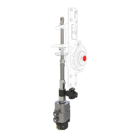
2 Synchronized Main Furling 2.1 SMF Retrofit kit – mast motor and clutch The SMF retrofit kit contains the electric mast motor and clutch assembly required to upgrade your existing manual line driver. The mast motor is installed inside the mast and controlled by connection cables linked to the Seldén Power Supply and SEL-Bus system. Furling gear bracket Extended furlin gear shaft Line driver Safety plug Clutch shaft Clutch assembly Clutch plunger Clutch bracket Motor brake Mast bushing (x3) Mast motor Individual size for each mast section Connection cables to Motor control unit – Furling mast (brown, grey, orange) 6mm , 5m... -
Page 6: Power Supply And Sel-Bus System
2.2 Power supply and SEL-Bus system SMF retrofit is used together with a Seldén Power supply and SEL-Bus system, and a Seldén electric winch for synchronized outhaul. The mast motor is connected to motor control unit (MCU) for furling masts. Via the SEL-Bus network, the fur- ling mast MCU can communicate with the winch MCU and OUT/IN control buttons. Seldén’s electric winch, all power supply and SEL-Bus system parts are sold separately. Parts and packages are described in Seldén Power Supply and SEL-Bus system: Order guide 597-283-E. System illustration The illustration shows an example of a Synchronized Main Furling network installation. The complete Power Supply and SEL-Bus system of each customer will vary and can include additional units and functions. 1. Battery (not included) 2. Main switch/fuse 3. Power supply unit (PSU) Converts 12/24V to 42V 4. Push buttons for Synchronized Main Furling 5. Electric winch 6. -
Page 7: Technical Specification
2.3 Technical specification Mast motor Total Gear Ratio 81:1 Peak Torque 16Nm 170Nm Low speed (max) 37 RPM 37 RPM High speed (max) 74 RPM 74 RPM Max power (full torque) 175W 740W Full load current* Nominal current* 7,5A *Consumption incl. MCU and PSU. Synchronized winch Limited outhaul force** 2200N... -
Page 8: Retrofit Installation
3 Retrofit installation 3.1 Installation preparations The installation can be performed with the mast installed on the boat or unstepped. Some minor additions to the existing gear cutout are required to allow fitting of the modified gear with clutch added, and motor unit. Extended gear cut out Extended furling gear shaft with clutch assembly, schematic picture Carefully review the cut out drawing before starting installation. Remove any fittings that will interfere with the fixing holes on port and starboard sides (e.g. winch handle pocket, cleats). This instruction does not cover how to route the motor connection cables out of the mast as this may be unique to each installation e.g. mast type, mast heel/base configuration and individual preferences. Installation Cut-out drawing per Mast section R290 597-847 The mast section is identified by the mast ID, engraved on port side at the bottom of the mast extrusion (see page 3). -
Page 9: Dismantle Manual Gear
Tools needed: Screwdriver - Flat Pop rivet gun. Torx key set -to replace mast heel, option “A”. Hex key set -to replace any removed fittings if needed. File (half round, medium/coarse) Hammer Drill bit for pop rivets. Punch -To remove mast heel, option “A”. Pliers (e.g. jaw pliers/adjustable spanner and long nose pliers) -To remove interfering fittings if needed. Power drill Drill bit Ø4.2, Ø6.4 Jigsaw Hole saw (24mm) -to extend gear bracket cut out (option ”B”) Tap M5 Wedges (included in package) Ethanol Pencil Heat gun and shrink tube (to protect cables) Measuring tape Cleaning spirit, cleaning cloth Line for lifting the mast motor during assembly (option B) Seldén grease 312-501 (included) Locking adhesive, 312-305 (included) Locking adhesive, medium strong Lubricant (WD-40 or similar) 3.2 Dismantle manual gear Free gear shaft from luff extrusion Release backstay tension if working on a stepped mast. - Page 10 Lock the tube in the upper position and prevent the luff extrusion from turning. Insert a winch handle in the linedriver and turn it anti-clockwise until the luff extrusion is slack. Through the lower greasing hole on the port side, remove the split pin and clevis pin from the gear shaft adapter. Save the split pin and clevis pin. Remove screws and dismount furling gear bracket from mast. Note; Retrofit assembly 540-681-43 requires special procedure, see point 7-10. Releasing the rig tension can facilitate dismounting of the furling gear bracket, if needed.
- Page 11 Remove Label & screws (12x) Pull out gear front with linedriver (A). Take care not to pull out gear body. (B) Remove screw, large bevel gear and ball bearing. Remove gear body.
-
Page 12: Modification Of Gear Procedure Vary Between Different Gear Assemblies
3.3: Gear modification. Procedure vary between different gear assemblies; Retrofit assemblies no. 540-681-35, -36, -37, -38 , -40, -41, -42; Only gear shaft is replaced. See chapter 3.3.1 Retrofit assemblies 540-681-39, -44, -45; Gear shaft and linedriver hub is replaced. See chapter 3.3.2. Retrofit assembly 540-681-43;... -
Page 13: Modification Of Gear, New Shaft
3.3.1 Modification of gear, new shaf t Remove the rubber cover. Note quantity and position of any washers and shims (A). Remove the spring pin (C) with a hammer and punch or equivalent. Carefully remove the shaft, saving the free bearing balls, races and washers. Spring pins will not be reused. Work on a surface where the loose bearing balls will not get lost. There should be 12 bearing balls in each ball race. Clean and apply grease on the ball bearings. The grease in the ball bearings will help keep the balls in position during reassembly. Install the new shaft and remount ball bearings and washers. Fit rubber cover (D) Remount the bevel gear. The hole in the bevel gear should be aligned with the hole in the shaft. Fit new spring pin: Ø8x45 (E). Connect clutch assembly to the extended gear shaft. Use the ball (F) and a hammer or a vise to deform and secure the rivet. If using a hammer, secure the ball to the rivet head with some adhesive tape while hammering. -
Page 14: Modification Of Gear, New Shaft & Linedriver Hub
3.3.2 Modification of gear, new shaf t & linedriver hub If gear is equipped with reinforcement frame (A), continue to point 6. Remove nut and screw and pull out vertical shaft. Remove vertical gearwheel. - Page 15 Remove spring pin, horizontal gear and bearing. Unscrew 4x screws and pull out linedriver and linedriver hub. Continue to point 12. Punch out spring pin and remove small bevel gear and linedriver wheel.
- Page 16 Remove screws at pos A & B Pull out shaft and remove gear, washers and bearings. Remove screws (4x) and linedriver hub...
- Page 17 Remove support bracket Clean all parts. Shorten linedriver shaft by 45 mm as shown above. (Note that some shafts are detachable into to two parts). Fit new linedriver hub. Use Loctite on screws. Grease shaft and reassemble linedriver. Lock with new spring pin.
- Page 18 Clean and apply grease on ball bearings. Install the new shaft and remount ball bea- rings and washers and vertical bevel gear. Adjust vertical position of shaft with washers at position A & B until the gear runs smoothly without excessive play.
-
Page 19: Modification Of Gear For Retrofit Assembly 540-681-43
3.3.3 Modification of gear for retrofit assembly 540-681-43 Remove screws, bracket and vertical shaft. Clean ball bearing race and insert new shaft. Remove pin and horizontal gear. (Removal of pin requires a lot of force) Unscrew 4x screws and pull out linedriver and linedriver hub. - Page 20 Replace linedriver shaft (A) & hub (B) and assemble. Use loctite on screws. Fit washer and gear. Fit pin and lock by deforming edge of hole.
-
Page 21: Installation Of Motor Unit
Installation of motor unit Installation varys slightly between different gear assemblies; Retrofit assemblies no. 540-681-35, -36, -37, -38 , -39,-40, -41, -42, -44, -45; See 3.4.1. Retrofit assembly 540-681-43; See 3.4.2. 3.4.1 Installation of motor unit, RC gear Expand the gear cut-out according to the provided installation cut out drawing, also cutting the backingplate. Avoid cutting in the nut. - Page 22 Plastic wedges supplied with the kit might be used to facilitate installation of motor and gear. Undo the four top screws (C) of the mast motor and dismantle the motor brake. Prepare the motor brake for later by attaching a line in the lifting eye (D). Feed the cables and insert the motor through the expanded hole.
- Page 23 Temporarily fasten the motor using the bushing and screw in the lower hole on the port side of the mast and the upper port hole of the motor i.e. the motor is positioned 37mm lower than its final position. (The lower position is needed to be able to fit the gear- and clutch assembly after the motor brake is installed). Remove wedges if these have been used. Reinstall the motor brake through the gear cut out. Small screw on brake to face aft, see picture. Let assembly hang on one plunger in its lower position. Use grease on screws. Tightening torque=7Nm. Insert gear and clutch assembly through the cut-out with the clutch arm facing towards the sail groove. The M6x60 screw (E) can temporarily be attach to the clutch arm to facilitate guiding of the clutch through the sail groove.
- Page 24 Apply grease on screws and fasten gear bracket. Connect mast motor. Be careful not to push out the nuts from the backing plates. Fix the mast motor to the mast wall with the included bushings and M10 screws. Use pliers/adjustable spanner to keep the bushings from rotating. The thicker flange edge (J) should be facing aft. (Tape the pliers to prevent chafing the bushings). Check the clutch gap as described below before applying medium strong locking adhesive to screws. Measure play as shown. If play is out of tolerance, contact your dealer.
-
Page 25: Installation Of Motor Unit, Assembly 540-681-43
3.4.2 Installation of motor unit, assembly 540-681-43 Expand the gear cut out according to the provided installation cut out drawing. Grind edges carefully along the whole edge. Clean the cut-out area. Drill locating holes for the mast motor to the dimensions found in the installation cut out drawing. Two holes on the port side, one hole on the starboard side. Use the center of the lower screw hole of the furling gear cut out (A) as the reference for the vertical dimension. B-line Use the B-line (vertical recess at the mast widest point) as the reference for the horizontal dimension. Chamfer the holes carefully with a file. Prepare for cable routing Fit the motor unit through the lower end of the gear cut-out. - Page 26 Temporarily fasten the motor using the bushing and screw in the lower hole on the port side of the mast and the upper port hole of the motor i.e. the motor is positioned 37mm lower than its final position. (The lower position is needed to be able to fit the gear and clutch assembly after the motor brake is installed). Place clutch on top of mast motor. Insert Gear body with new shaft...
- Page 27 Fit large gear wheel with cleaned and greased ball bearing and secure with screw. Use Loctite on screw. Fit the screw (A) in the clutch bracket. Lift the clutch assembly and fit to gear with screw and nut (B). Place 2 washers each side of join. Fit nut with Loctite. Fit gear bracket front, first with 4x screws with grease to gear body and then 8x screws with Loctite to backing plates.
- Page 28 Fix the mast motor to the mast wall with the included bushings and M10 screws. Use pliers/adjustable spanner to keep the bushings from rotating. The thicker flange edge (J) should be facing aft. (Tape the pliers to prevent shafing the bushings). Check the clutch gap as described below before applying medium strong locking adhesive to screws. Measure play as shown. If play is out of tolerance, contact your dealer.
-
Page 29: Installation Of Clutch Plunger
3.5 Installation of clutch plunger and bracket On an unstepped mast, push the clutch towards the mast motor (to simulate that it is standing on top of the mast motor). Through the sail groove, mount the clutch plunger (A) on to the clutch lever with screw and spring included in misc pack. - Page 30 Motor Manual Place the clutch bracket (B) on the mast wall, with the clutch plunger placed in the lower position “motor”. Make sure the clutch, clutch plunger and bracket is positioned as low as possible. Mark hole positions. Control position of the clutch bracket holes by changing between Motor and Manual mode. In Manual mode the torque con- nector should be completely disengaged from the motor unit. Drill and tap 2xM5 holes. Fasten the clutch bracket, use locking adhesive. Remount the clutch screw with medium strong locking adhesive and align the screw head with the clutch plunger.
- Page 31 Fit the clevis pin and split pin to fix the gear shaft to the adapter (A). Open the split pin to min 20° Re-tension luff profile to correct tension according to chapter 4.1. Ensure that the gear controller arm is set in FREE mode (C) and put plug in winch socket (D). The manual furling gear should always be set to FREE when connected to the mast motor. Reassemble plugs and covers for greasing and access holes on mast. Lead the mast motor connection cables out of mast. Remount mast heel, if applicable.
-
Page 32: Connection To Seldén Power Supply And Sel-Bus System
3.6 Connection to Seldén Power Supply and SEL-Bus system Install the three control cables from the mast motor to the motor control unit (MCU) “Furling mast”. Carefully note the position of cable colour and connector: L3= Grey L2= Orange L1= Brown The cables need to be connected to the MCU in the correct position/sequence. Incorrect positioning of the cables can damage the mast motor and the break mechanism. For correct positioning of the Motor Control Unit, installation of the complete Power supply and SEL-Bus system, see separate manual 597-275-E. -
Page 33: Configuration Of Control Buttons For Synchronized Main Furling
3.7 Configuration of control buttons for Synchronized Main Furling For synchronized main furling, configuration of the control buttons for both the winch and furling mast must be done in the following order. For complete information about how to configure Motor control unit, MCU, to the control buttons, read installation manual 597-275-E. A. Configure winch MCU to winch buttons Press the configuration button on Winch MCU. Push and hold winch button 1 or 2 until the winch generates the start-up signal. Press the configuration B. Configure winch MCU to the MAIN OUT button on Winch MCU. button (for synchronized outhaul) Push and hold MAIN OUT until the winch generates the start-up signal. C. Configure furling mast MCU to the MAIN Press the configuration OUT/IN buttons button, on Furling mast MCU. Push and hold IN until the mast motor generates the start-up signal. If the signal tone is generated when the Power supply and SEL-Bus system is turned on (without any button being pressed) turn the power off immediately. Inspect the push button connections; cables from SEL-Bus converter to push button must be installed as “normally open” not “normally closed”. -
Page 34: Preparations Before Sailing
Preparations before sailing 4.1 Tensioning the luf f extrusion It is important that the luff extrusion inside the mast is correctly tensioned. An untensioned or over-tensioned luff extrusion can lead to increased furling load or unnecessary wear of the system. Control and adjustment of luff tension can be made on both a stepped and unstepped mast. The luff extrusion should be prevented from rotating. Use a torque wrench in the furling gear winch handle socket to measure the tensioning torque. Alternatively, measure the torque with a spring balance or similar combined with an ordinary winch handle. Tension to the correct value as required. It is important that the mast is straight while tensioning. Torque Force (F) Type Measured with 10” winch handle RC system 8 Nm 32 N Always release backstay tension before adjusting luff extrusion. Tensioning the luff extrusion with the backstay tensioned can damage the luff extrusion joints when the backstay tension is released. 4.2 Rig tuning Furling in and out will work best on a mast tuned with limited prebend. Read 595-540-E Hints and Advise for tuning instructions. -
Page 35: Outhaul Car Stop
4.3 Outhaul car stop The position of the outhaul car stop on the boom will affect tension in the sail foot and leech. E.g. if the outhaul is posi- tioned too far aft, the force from the outhaul clew will keep the foot tighter than the leech which can cause the sail to jam in the top of the mast. The ideal position can vary between boats due to rig, sail and batten designs. It is recommended to place the outhaul stop 500 mm from the aft mast wall as default, and then adjust it forward or aft if necessary. 4.4 Outhaul routing Examine outhaul car and outhaul turning points for excessive friction. Replace old and worn blocks if needed. Outhaul routing with as low friction as possible will improve the unfurling process. Synchronized outhaul winch The force limit in the synchronized outhaul winch is based on the line force at winch entry. High fric- tion in the outhaul routing will result in the actual force in the outhaul clew being significantly lower than at the winch, which can negatively affect the synchronization. -
Page 36: Sailing With Synchronized Main Furling
Sailing with Synchronized Main Furling The manual furling gear must be set to FREE when connected to the electric motor. The clutch plunger should be positioned in the lower seat (MOTOR). 5.1 Preparations for furling and unfurling There are many factors to consider for a successful furling operation. Get familiar with the furling system in light conditions and pay attention to the following details before furling out and in. How important these adjustments are for the furling result can vary between boats, sail designs and other factors. SAIL UPWIND Sail upwind. RELEASE BACKSTAY Release backstay tension (if very tight) to straighten the mast and increase the tension in the luff extrusion. Adjust the boom angle to keep the leech tight and battens parallel to mast. ADJUST Use kicker/topping lift. BOOM ANGLE Ease the main sheet. EASE MAIN SHEET Always observe the entire furling process! Stop immediately in case of any issues. Keep away from the sail groove, winches and any other moving parts during furling. Ill. Dan Ljungsvik/Seldén 2018... -
Page 37: Unfurling
5.2 Unfurling Apply and secure the outhaul to the synchronized electric winch. Press “Furl Out”. The outhaul winch will make a short warning signal before starting to run. Remote control of a sailing winch is hazardous. Always observe the unfurling process and ensure nothing can interfere with the winch, outhaul line or sail groove in the mast. Whilst holding down “OUT”, press the second button to increase the speed, if wanted. Full sail Hold button(s) pressed. The synchronized system The motor will make a short rotation will recognize a fully unfurled sail and stop automa- when unfurling is finished, to activate tically. the break mechanism. Reduced sail area Release button(s) when sail is in desired position. If needed, the outhaul can be trimmed using the winch buttons. Be careful when using the winch buttons, as this activates the full power of the winch. Ill. Dan Ljungsvik/Seldén 2018... -
Page 38: Furling
5.3 Furling Free the outhaul and keep it tensioned (about one turn on the winch). Press “IN” and simultaneously slacken the outhaul line while the sail is reefed. Whilst holding down “IN”, press the second button to increase the speed. Release the button(s) and stop reefing at desired sail area or when sail is fully furled in. The motor will NOT automatically stop during furl in. Run the last turns with low speed and keep attention to the position of the outhaul block to prevent it from being pushed into the sail groove and damage the mast. -
Page 39: Manual Drive
5.4 Manual drive In case of electric or mast motor failure, the sail can be manually reefed by disengaging the motor from the manual gear: Disconnect mast motor Turn power off! Wiggle the line driver by hand to remove initial stress from the clutch. Furling/reefing: Put controller to the port side (”in”). This engages the ratchet function in the manual gear winch. Unfurling: Keep controller in ”free” position. Pull the Clutch Plunger out and up, switching to the upper position. The mast motor is now disconnected from the furling gear. Furling/reefing: Remove the safety plug from the winch socket. Use a winch handle to manually furl in the sail at the mast. Unfurling: Pull the outhaul line manually or carefully use the electric winch. Do not use a winch handle in the line driver, as this will rotate very quickly if the wind catches the sail. For more frequent use without using the motor, a control line can be fitted like on any Seldén Manual furling gear. Remove winch handle from socket when done. -
Page 40: Furling Without Synchronized Winch
Reconnect electric motor: Pull the Clutch Plunger out and down. If needed, rotate the linedriver to adjust the angle of the clutch shaft inside the mast, until the shaft connects to the motor. Put furling gear in FREE mode The gear should always be in FREE mode when motor is engaged. Put the safety plug back into the winch socket. 5.5 Furling without synchronized winch If the synchronized winch is not to be used, the outhaul can be pulled manually without disconnecting the furling mast motor. 1. Press and hold “MAIN OUT”. The mast motor will start to rotate but pauses automatically if the outhaul is not pulled, to avoid the sail being unfurled inside the mast. 2. Keep “MAIN OUT” button pressed. Pull the outhaul manually. The furling motor will start to rotate when it detects that the outhaul is being pulled. Proceed until desired sail area is reached. When OUT button is relea- sed, the mast motor will activate the rotation break. -
Page 41: Trouble Shooting
Trouble shooting Problem Problem cause Action Mast motor makes a stuttering Incorrectly installed connection Change position of connec- sound and unfurling does not cables to MCU. tion cables in MCU according work to section 3.6 Mast motor makes a constant Cables from SEL-Bus converter Change position of push signal tone when Power to push button is installed as button cables to “Normally Supply and SEL-Bus system is “Normally closed” instead of open”, see separate instruc- turned on. “Normally open”. tion sheet for push button. Mast motor starts to run when Power Supply and SEL-Bus system is turned on, and stops when Furling MAIN OUT/IN button is pressed. Synchronized unfurling is not Incorrect tension in luff profile, See chapter 4. smooth. rig tuning, outhaul car position, outhaul routing. Top of sail is jamming Incorrect tension in luff profile, See chapter 4. -
Page 42: Service And Maintenance
Service and maintenance Always keep the manual furling system in good condition, following the service and maintenance procedures described in each respective manual furling mast instruction. 7.1 Annual maintenance Lubricate motor brake Through the sail groove, remove the screw to the lubrication hole (A). Apply WD-40 in the hole and simultaneously rotate the mast motor minimum one turn. Remount screw. 7.2 Extended maintenance Professional service should be made on the mast motor every 5th year. Contact an authorized Seldén dealer for service management. -
Page 43: Disposal
Disposal The crossed out wheelie bin symbol on the product or product package means that used electrical and electronic equipment (WEEE) should not be mixed with general household waste. For proper treatment, recovery and recycling, please take this product(s) to designated collection points where it will be accepted free of charge. Alternatively, in some countries, you may be able to return your pro- ducts to your local retailer upon purchase of an equivalent new product. Disposing of this product correctly will help save valuable resources and prevent any potential negative effects on human health and the environment, which could otherwise arise from inappropriate waste handling. Please contact your local authority for further details of your nearest designated collection point. Warranty Seldén Mast AB guarantees SMF retrofit kit for 2 years. The guarantee covers faults arising from defective design, materials or workmanship. The guarantee is only valid if the SMF retrofit kit is assembled, operated and maintained in accordance with this manual and is not subjected to loads in excess of those indicated in the brochure and instructions. Complete shipment and warranty conditions are to be found on Seldén’s website www.seldenmast.com. See Resources/Partners information/General information/General conditions of sale (595-546-E). If the system is repaired or modified by anyone other than Seldén Mast AB or one of our authorized dealers, the guarantee ceases to be valid. Seldén Mast AB reserves the right to alter the content and design without prior warning. - Page 44 www.seldenmast.com...
Need help?
Do you have a question about the SMF RC and is the answer not in the manual?
Questions and answers