Table of Contents
Advertisement
Quick Links
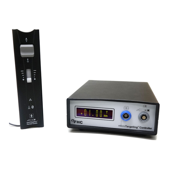
microTargeting™ Controller Power Assist System
Directions For Use
L011-80 (Rev C0, 2020-11-05)
Contains directions for the following products:
66-DS-PA, 66-EL-MS, 66-EL-RM, 66-DA-ME, 66-DA-SD
www.fh-co.com
FHC, Inc.
1201 Main Street
Bowdoin, ME 04287 USA
Fax: +1-207-666-8292
24 hour technical service:
1-800-326-2905 (US & Can)
+1-207-666-8190
FHC Europe
(TERMOBIT PROD srl)
42A Barbu Vacarescu Str, 3rd Fl
Bucharest 020281Sector 2
Romania
FHC Latin America
Calle 6 Sur Cra 43 A-200
Edifi cio LUGO Ofi cina 1406
Medellín-Colombia
Advertisement
Table of Contents

Related Manuals for FHC microTargeting 66-DS-PA


Summary of Contents for FHC microTargeting 66-DS-PA
- Page 1 Directions For Use L011-80 (Rev C0, 2020-11-05) Contains directions for the following products: 66-DS-PA, 66-EL-MS, 66-EL-RM, 66-DA-ME, 66-DA-SD www.fh-co.com FHC Latin America 24 hour technical service: FHC, Inc. FHC Europe Calle 6 Sur Cra 43 A-200 1-800-326-2905 (US & Can)
- Page 2 Page 2 of 17 L011-80 Rev. C0 2020-11-05...
-
Page 3: Table Of Contents
Table of Contents: Indications for use and Intended use Symbol Key Classifications Operating Environment Storage and Transport Conditions Warnings and Cautions Inventory Cleaning Replacing the Fuses Installation and Functional Checkout Sterile Draping Procedure Illustrative Procedure Basic pre-use checkout Prepare the controller for use with the drive Assemble and connect the motor unit Zero the drive Typical operative use... -
Page 4: Indications For Use And Intended Use
Directive 93/42/EEC and legal responsibilities as a manufacturer are on the order of a physician. with FHC, Inc., 1201 Main Street, Bowdoin, ME 04287 USA. In reference to “Rx only” symbol; this applies to USA Authorized Representative in the European Community. -
Page 5: Operating Environment
Operating Environment: The controller and accessories are designed to be used in the normal operating room environment and require no special handling or care exceptional to other electronic devices used in that environment. The controller and hand held remote control should be positioned within 3 meters of but outside the sterile field, the motor unit is sleeved inside a sterile drape sleeve and mounted on the drive within the sterile field. -
Page 6: Inventory
Prior to its initial use, set up the microTargeting™ Controller Power Assist System for an initial installation checkout. Practicing the mounting and FHC Part Number: E1-06-09 engagement procedure and the assembly draping procedure several Fuse Type: 5 x 20mm 250VAC 1Amp Slow Blow times before the first surgical use will familiarize personnel with the required steps. -
Page 7: Sterile Draping Procedure
Sterile Draping Procedure: Draping the motor can be accomplished by one person, - Push the pins but is facilitated if an assistant is present. The one-person and center drive plate through method will require a sterile gloved hand ( ) for the cutouts and smooth the the drape. -
Page 8: Illustrative Procedure
Illustrative Procedure: Basic pre-use checkout Visually inspect the components that are going to be used prior to the procedure. Ensure that: • No major physical damage (beyond what can be expected under normal use conditions, such as minor scratches of the surface) can be seen on the enclosures of the controller or the remote control •... -
Page 9: Assemble And Connect The Motor Unit
Assemble and connect the motor unit Remove the sterilization cover on the motor unit and the drive, if they are attached. The motor unit must be draped to maintain sterility of the drive, it should not be sterilized. For detailed step by step instructions on the proper draping of the motor unit while maintaining sterility, please refer to the “Sterile Draping Procedure”... -
Page 10: Zero The Drive
12. Plug the motor unit into the controller by inserting its connector into the corresponding socket on the front panel. Zero the drive 13. Activate the ON/OFF switch of the controller module. The controller should boot and display the “Set drive origin” message. -
Page 11: Typical Operative Use
16. Press the zero button on the remote control to indicate that the current position is at 0 µm. From now on, pressing and holding down the Zero button for 3 seconds will return the drive to this position. Zero button 17. -
Page 12: After Completion Of The Procedure
Frequent stall indications are a sign that there may be a physical problem with the drive resulting in excessive torque requirements, or a problem with the motor unit or controller. Contact FHC for additional diagnostic help and to set up a repair. Page 12 of 17 L011-80 Rev. -
Page 13: Reference Information
In order to be environmentally responsible, the microTargeting™ Controller Power Assist System should not be disposed of in a landfill or with municipal waste. FHC will gladly recycle the system once it has reached its end of life in an environmentally responsible manner. Please contact your local FHC representative for instructions on where to return the microTargeting™... -
Page 14: Technical Summary
Technical Summary: Physical Dimensions Controller Module Hand-held Remote Motor Width 16 cm 5 cm 3 cm Height 7 cm 4 cm 8 cm Length 21 cm 19 cm 2 cm Weight 0.8 kg 0.2 kg 0.1 kg Mechanical and Material Profile Case Material: ABS, Non-conductive, UL94 V-O Display:... -
Page 15: Concepts And Terminology
Concepts & Terminology: Auto-Retract: Pressing and holding the zero button for approximately three seconds will initiate the auto-retract function. Once initiated, the controller will retract the motor at top speed to the origin point. If an initial offset has been specified, this is where the drive will stop. Initiating the auto-retract function while at the initial offset origin will cause the drive to retract to the zero point. -
Page 16: Declarations Of Electromagnetic Emissions And Immunity
Declarations of Electromagnetic Emissions and Immunity Declaration of Emissions: The mT Controller is intended for use in the electromagnetic environment specified below. The operator should ensure that it is used in such an environment. The mT Controller is suitable for use in all establishments, other than domestic, and those directly connected to the public low-voltage power supply network that supplies buildings used for domestic purposes. - Page 17 Recommended Separation Distances: The mT Controller is intended for use in the electromagnetic environment in which radiated disturbances are controlled. The customer or user can help prevent electromagnetic interference by maintaining a minimum distance between portable and mobile RF Communications Equipment and the mT Controller as recommended below, according to the maximum output power of the communications equipment.
Need help?
Do you have a question about the microTargeting 66-DS-PA and is the answer not in the manual?
Questions and answers