Table of Contents
Advertisement
Quick Links
Advertisement
Table of Contents

Related Manuals for Theben PlanoSpot 360 DALI-2 S DE Series


Summary of Contents for Theben PlanoSpot 360 DALI-2 S DE Series
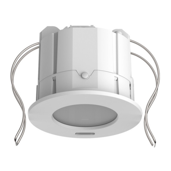
- Page 1 Manual DALI-2 presence sensor PlanoSpot 360 DALI-2 S DE 2020-04-27_307458...
-
Page 2: Table Of Contents
Contents General Safety information Proper use Explanation of terms Function description Overview of available instances Technical data Product characteristics Usage Functionality Dimensions Detection area Infrared receiver Display/visualisation Connection Installation Ceiling installation Operation Settings via remote control Settings via the DALI bus Status messages via the DALI bus Light measurement Light measurement... -
Page 3: General
1 General 1.1 Safety information ATTENTION Installation should only be carried out by a qualified electrician! 1.2 Proper use The PlanoSpot 360 DALI-2 S is intended for indoor installation. It serves as a DALI-2 input device and transmits the collected sensor data to the multi-master application controller. The PlanoSpot 360 DALI-2 S is exclusively intended for use as contractually agreed between the manufacturer and the user. -
Page 4: Function Description
2 Function description The PlanoSpot 360 DALI-2 S devices are integrated into a higher-level system. Thanks to the DALI-2 standard, a multi-master application controller from any manufacturer may be used. This controller must support IEC 62386 Parts 101/103 and optionally – in order to use the information regarding presence as well as brightness –... -
Page 5: Technical Data
3 Technical data Operating voltage DALI (in accordance with IEC 62386-101): 10 V – 22.5 V Power input max. 10 mA Connection type Plug-in terminals Cable cross-section 0.5 – 1.5 mm Type of installation Ceiling installation with springs Size of flush-mounted housing Size 1 (NIS, PMI) Recommended installation 2.0 –... -
Page 6: Product Characteristics
4 Product characteristics 4.1 Usage The focus is on purpose-built facilities, within the following applications in particular: • Offices • Large offices • School rooms • Conference rooms • Corridors 4.2 Functionality • The PlanoSpot 360 DALI-2 S provides information about presence and brightness in the form of a DALI telegram in line with IEC 62386 Part 303/304. -
Page 7: Dimensions
4.3 Dimensions 4.3.1 Ceiling installation with springs 4.3.2 Surface-mounted installation with 75B back box PlanoSpot 360 DALI-2 S DE manual... -
Page 8: Detection Area
4.4 Detection area The square detection area of the PlanoSpot 360 DALI-2 S presence sensor guarantees accurate and simple planning. There are 2 detection zones available. Note that seated and walking persons are detected in differently sized areas. The recommended installation height is 2–3 m. As installation height increases, the sensitivity of the PlanoSpot 360 DALI-2 S decreases. -
Page 9: Infrared Receiver
4.5 Infrared receiver An infrared receiver can be used to receive parameters and control commands. This process involves unidirectional communication. The PlanoSpot 360 DALI-2 S can be operated with the following remote controls: − theSenda B/theSenda Plug remote control (9070985) −... - Page 10 No short address: 160 ms repeating every 2.36 s No short addresses assigned to the sensor Presence test: LED lights up if motion is detected, otherwise switched off; applies until presence test is completed. Start-up phase: 1,280 ms 30 s long Start-up flashing PlanoSpot 360 DALI-2 S DE manual...
-
Page 11: Connection
5 Connection The PlanoSpot 360 DALI-2 S devices are connected to the DALI line. An external DALI supply is required for operation of the PlanoSpot 360 DALI-2 S devices. This DALI supply must be able to ensure a reliable power supply for all connected DALI participants. -
Page 12: Installation
6 Installation 6.1 Ceiling installation Installation in false ceilings for ceiling thicknesses of 0.5 mm to 3 cm. The drill diameter for the ceiling cut-out is 68 mm. Remove the contact protection (a) and connect the DALI cable with plug-in terminal (b). Implement cable strain relief with cable tie, put on contact protection (c). Open springs and mount detector in ceiling (d). -
Page 13: Operation
7 Operation All settings are configured via the DALI bus or the remote control. In its initial delivery condition, the PlanoSpot 360 DALI-2 S does not have a short address. 7.1 Settings via remote control The theSenda B/app and theSenda P remote controls can be used to set the following parameters and control commands. - Page 14 IR group IR group address button address B instance 8–9 Range: I/II/III/ ../VIII/All IR group IR group address button address C instance 10–11 Range: I/II/III/ ../VIII/All IR group IR group address button address D instance 12 Range: I/II/III/ ../VIII/All IR group IR group address button address E...
- Page 15 We recommend the following procedure: Place the lux meter or theSenda B remote control with integrated lux meter on the work surface under the PlanoSpot 360 DALI-2 S, enter the measured lux value via theSenda B/app remote control (parameters <Brightness measurement value Int/2, Inn/3, Mid/4, Win/5>) and send to the PlanoSpot 360 DALI-2 S.
- Page 16 Operating mode In its factory settings, the PlanoSpot 360 DALI-2 S is set to DALI-2 standard (operating mode 0x00). The proprietary DALI mode 0x80 or 0x81 was used for older systems. If the PlanoSpot 360 DALI-2 S is to be integrated into such a system, the relevant operating mode – 0x80 or 0x81 – can be selected.
- Page 17 Presence test mode Presence test mode is used to test presence detection. Presence test mode can be activated with the theSenda B/app or with the theSenda P installation remote control ( button). When the test mode is set, the PlanoSpot 360 DALI-2 S switches directly to test mode: •...
-
Page 18: Settings Via The Dali Bus
7.2 Settings via the DALI bus All of the parameters* and control commands described above can also be set by the multi- master application controller via the DALI bus. They are stored in the memory bank. * Exceptions: "Brightness measurement value Int/2, Inn/3, Mid/4, Win/5" and "LED display – no short address"... -
Page 19: Light Measurement
8 Light measurement 8.1 Light measurement The mixed light measurement measures artificial light and daylight. It provides consistent measurement results regardless of the light source. The artificial light from fluorescent lamps and LEDs is detected correctly despite the discrete spectrum. The light measurement device is located under the lens and receives diffuse light as a result. -
Page 20: Determining A Value Via The Dali Bus
8.2 Determining a value via the DALI bus According to DALI standard IEC 62386-103/304, the value of a light sensor instance is obtained either by querying directly or by evaluating the events. 8.2.1 Direct queries The following steps must be carried out in order to query the value directly: Address the DALI telegram "QUERY INPUT VALUE"... -
Page 21: Operating Modes
9 Operating modes The PlanoSpot 360 DALI-2 S presence sensor is an input device and is exclusively intended to provide information about room occupancy and motion detection in accordance with IEC 62386 Part 303 (movement based sensor) as well as brightness values in accordance with IEC 62386 Part 304 to a higher-level controller via the DALI bus. -
Page 22: Memory Bank 7-11 - Button Instance
The assignment of the memory banks to the light sensors is as follows: • Instance 2 provides integral brightness values: Memory bank 3 • Instance 3 provides interior brightness values: Memory bank 4 • Instance 4 provides middle brightness values: Memory bank 5 •... - Page 23 Memory bank 9 Default RESET Memory Address Description value value type (factory) Address of last position 0x00 0x03 no change in this MB Indicator byte (defined by manufacturer) – 0x01 0x01 no change version of the memory bank 0x02 Memory bank lock byte 0xFF 0xFF IR group address button...
-
Page 24: Start-Up Behaviour
The value range for the "IR group address button instance 13" instance variables is I (0x01) to VIII (0x08) and All (0xFF), see also section 7.1.1 Parameters. 9.4 Start-up behaviour When the PlanoSpot 360 DALI-2 S is connected to a power supply or if it is restarted, it goes into the start-up phase for a defined period of time before switching to normal operation. -
Page 25: Button Function
9.8 Button function The PlanoSpot 360 DALI-2 S partially supports the button instances defined in IEC 62386 Part 301. The theSenda S or theSenda B user remote controls can be used to dim or switch the lamps, to control the blinds, or to execute additional functions. The remote control commands are sent to the PlanoSpot 360 DALI-2 S via the IR interface. - Page 26 Events are only triggered if the IR group address set in the relevant memory bank matches the IR group address for the remote control. Further information about setting the IR group addresses for the remote control can be found in the operating instructions for the theSenda B or theSenda S.
-
Page 27: Accessories
10 Accessories Back box 75B WH Item no.: 9070796 Details > www.theben.de/en PlanoCover 76 BK Item no.: 9070592 Details > www.theben.de/en PlanoCover 76 SR Item no.: 9070592 Details > www.theben.de/en theSenda B Item no.: 9070985 Details > www.theben.de/en theSenda P Item no.: 9070910... - Page 28 S Item no.: 9070911 Details > www.theben.de/en PlanoSpot 360 DALI-2 S DE manual...
-
Page 29: Contact
11 Contact Theben AG Hohenbergstr. 32 72401 Haigerloch GERMANY Phone +49 7474 692-0 Fax +49 7474 692-150 Hotline Phone +49 7474 692-369 hotline@theben.de Addresses, telephone numbers, etc. www.theben.de/en PlanoSpot 360 DALI-2 S DE manual...
Need help?
Do you have a question about the PlanoSpot 360 DALI-2 S DE Series and is the answer not in the manual?
Questions and answers