Advertisement
ISL68137-61P-EV1Z Evaluation Board Quick Start User
Guide
Description
The ISL68137-61P-EV1Z evaluation board provides users a
method of evaluating the
Included on the board is a high-performance transient load
generator capable of replicating the type of high di/dt loads
typical of today's high current ASICs.
The ISL68137 is combined with the ISL99227 Smart Power
Stage (SPS) to provide a highly efficient power solution
capable of delivering up to 270A.
While the user may opt to evaluate the solution based on the
Intersil default configuration, custom configurations are easily
created using PowerNavigator™.
Specifications
This board has been configured and optimized for the following
operating conditions:
• 0.6V to 1.8V output range. Up to 3.05V with BOM change
• 6+1 phase: 270A + 30A
• Input range from 5V to 16V
October 10, 2016
UG097.0
Arrow.com.
Downloaded from
ISL68137
digital multiphase device.
1
Intersil (and design) and PowerNavigator are trademarks owned by Intersil Corporation or one of its subsidiaries.
Key Features
• 0.5% V
regulation accuracy
OUT
• PMBus interface, AVSBus interface
• 3% I
telemetry accuracy
OUT
• Onboard transient load to facilitate testing
• ATX or bench supply connections for input sources
Related Literature
• For a full list of related documents please visit our website
-
ISL68137
Ordering Information
PART NUMBER
ISL68137-61P-EV1Z ISL68137 evaluation board, 6+1 dual output
CAUTION: These devices are sensitive to electrostatic discharge; follow proper IC Handling Procedures.
1-888-INTERSIL or 1-888-468-3774
All other trademarks mentioned are the property of their respective owners.
User Guide 097
product page
DESCRIPTION
(EVB, PMBus adapter, AVSBus adapter, two USB
cables)
|
Copyright Intersil Americas LLC 2016. All Rights Reserved
Advertisement
Table of Contents

Related Manuals for Intersil ISL68137-61P-EV1Z


Summary of Contents for Intersil ISL68137-61P-EV1Z
- Page 1 1-888-INTERSIL or 1-888-468-3774 Copyright Intersil Americas LLC 2016. All Rights Reserved UG097.0 Intersil (and design) and PowerNavigator are trademarks owned by Intersil Corporation or one of its subsidiaries. All other trademarks mentioned are the property of their respective owners. Arrow.com.
- Page 2 470pF PHASE FAULT# TMON1 ISL99227 CONFIG PVCC TMON 470pF PWM6 IMON 2x22µF CSRTN6 REFIN BOOT 0.1µF 0.1µF 470pF PHASE FAULT# RGND1 VSEN1 FIGURE 1. ISL68137-61P-EV1Z BLOCK DIAGRAM Submit Document Feedback UG097.0 October 10, 2016 Arrow.com. Arrow.com. Downloaded from Downloaded from...
- Page 3 User Guide 097 FIGURE 2. CONNECTIONS Submit Document Feedback UG097.0 October 10, 2016 Arrow.com. Arrow.com. Arrow.com. Downloaded from Downloaded from Downloaded from...
-
Page 4: Functional Description
Intersil USB to PMBus dongle provided with the evaluation board. Transient load waveforms may be controlled using an internal J104 provides an interface to the Intersil USB to AVSBus dongle. oscillator or an external oscillator on J17. When using the internal... -
Page 5: Default Configuration Settings
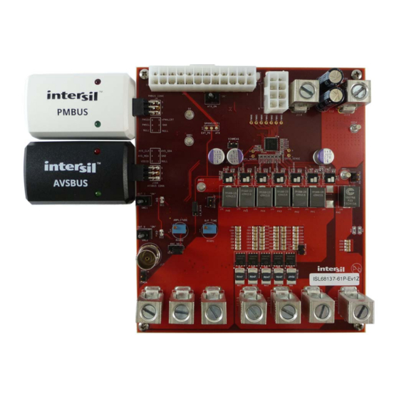
8. Wait until PowerNavigator™ Power Map is populated and the telemetry meters are displayed (Figure Guidelines Intersil provides both a schematic checklist and PCB layout guide for the digital multiphase IC family. These are available at the ISL68137 product page. In addition, full schematics, PCB files and BOM are provided for this evaluation board. - Page 6 User Guide 097 ISL68137-61P-EV1Z Evaluation Board PMBUS AVSBUS TRANSIENT CONNECTOR CONNECTOR LOAD VOUT1 INPUT VOUT0 12V BENCH SUPPLY INPUT INDUCTORS AND SPS FIGURE 8. TOP SIDE FIGURE 9. BOTTOM SIDE Submit Document Feedback UG097.0 October 10, 2016 Arrow.com. Arrow.com. Arrow.com.
-
Page 7: Typical Performance Curves
FIGURE 14. SOFT-START RAMP INITIATION FIGURE 15. SOFT-START RAMP COMPLETION Intersil Corporation reserves the right to make changes in circuit design, software and/or specifications at any time without notice. Accordingly, the reader is cautioned to verify that the document is current before proceeding.
Need help?
Do you have a question about the ISL68137-61P-EV1Z and is the answer not in the manual?
Questions and answers