Advertisement
Quick Links
Quick Installation Guide
Grid-tie Transformerless Hybrid Inverter
User manual / DC1
manual / APP download / APP guideline
_100
Please scan QR-code for more instruction, specification
and settings of DC1
- https://mydeltasolar.deltaww.com/?p=product_manual
Descriptions of Parts and Components
①
④
⑥
③
Object
Qty
①
PV Inverter
1
Quick
②
Installation
1
Guide
③
AC Plug
1
④
DC Plug
2 pairs H4 connector for DC connection
⑤
Wall-Mount
1
Bracket
⑥
Multi function
1
connector
⑦
Security Seal
4
If there is any visible damage to the inverter/accesories or any damage to
the packaging, please contact your inverter supplier before installation.
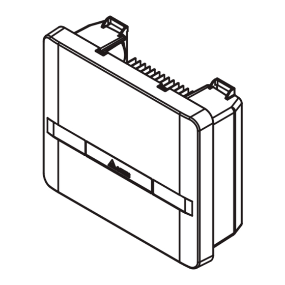
Dimensions and Function Introduction
130
91
380
DC2+
DC1+
BT+
DC2-
DC1-
BT-
DC switch
DC connectors x2
Function port
BT connectors x1
Model name: H5E_220
or APP.
_100
②
⑦
⑤
Description
Solar inverter
Important safety instructions and technical
specifications should be followed during installation.
Connector for AC connection
To mount the solar inverter securely on the wall.
Connector for DRM, RS485, VSG and battery
communication function.
Tamper stickers for Taiwan use only.
Caution
AC
OUTPUT
AC connector
Grounding
Comm. Interface
Do not install the unit near or on flammable surfaces.
Mount the unit tightly on a solid/smooth surface.
When the photovoltaic array is exposed to light, it supplies a DC voltage to the Inverter,
a shock hazard may exist due to output wires or exposed terminals.
To reduce the risk of shock during installation, cover the array with an opaque (dark)
material and ensure that the Disconnect Device in the inverter is set to OFF before
commencing any wiring.
Before commencing AC wiring, please ensure all AC circuit breakers are switched off.
During operation of electrical devices, certain parts are under dangerous voltage.
Inappropriate handling can lead to physical injury and material damage.
Always adhere to the installation regulations.
Installation may only be conducted by certified electricians.
The maximum open circuit voltage of the PV Array must not exceed 600Vdc.
The product supports wireless communication.
- Install the product as far away as possible from devices that emit strong radio waves,
such as civil band radio equipment.
- Do not install the product in metal box and make sure there is no metal barrier between
the product and connecting devices to prevent the communication signal attenuation.
- When using Wi-Fi to connect the inverter, the connection signal strength is
recommended to be at least -70 dBm to ensure good communication quality.
Mounting
①
Φ6.0*6
unit: mm
②
③
unit: mm
LED and Button
LED
Action
100ms On, 100ms Off
Alarm
Steady on
100ms On, 100ms Off
Grid/
1s On, 1s Off
SPS
2s flash(100ms), 2s on
Steady on
3s On, 3s Off
3s Flash(100ms), 3s Off
Off
Wi-Fi
Steady on
Label
100ms On, 100ms Off
500ms On, 500ms Off
1s On, 1s Off
Reset button
Push 3s~10s
Push 10s~20s
Push 20s~
Warning
Caution
227
60
7.5
250
22.5
291
37.5
Status
Insulation
Error or Fault. (see user manual - Chapter 10)
Default Country Setting
Countdown
The inverter is operating in standalone mode
On grid
Connected to Wi-Fi router/DC1
Connected to both WiFi router/DC1 and mobile device
Not connected
Connected to mobile device
Connected to mobile device and transferring data
Reboot Wi-Fi (Press Button 3~10s)
Reset password & Wi-Fi settings (Press Button 20~30s)
Wi-Fi LED Status
Description
Wi-Fi LED flashing once every
Reset Wi-Fi module
half a second
No flash
No function
Wi-Fi LED flashing once every
Reset Wi-Fi module, and Wi-Fi password
one seconds
returns to the default: DELTASOL
Advertisement

Subscribe to Our Youtube Channel
Related Manuals for Delta H5E 220


Summary of Contents for Delta H5E 220
- Page 1 Warning Quick Installation Guide Do not install the unit near or on flammable surfaces. Grid-tie Transformerless Hybrid Inverter Mount the unit tightly on a solid/smooth surface. Model name: H5E_220 When the photovoltaic array is exposed to light, it supplies a DC voltage to the Inverter, a shock hazard may exist due to output wires or exposed terminals.
- Page 2 DC input (Battery side) 75% of rated power Max. voltage 600 Vdc DRM4/8 REF GEN/0 DRM 8 - Increase power generation Compatible brand DELTA Compatible battery box BX6.3_DD ■ CAN(DD) connection (optional) Stand-alone mode ¹ Maximum power ² 5000 VA PIN 7 Max.
Need help?
Do you have a question about the H5E 220 and is the answer not in the manual?
Questions and answers