Delta H2.5 Operation And Installation Manual
Grid-tie transformerless solar inverter
Hide thumbs
Also See for H2.5:
- Operation and installation manual (37 pages) ,
- Comissioning manual (10 pages) ,
- Quick installation manual (2 pages)

Subscribe to Our Youtube Channel
Related Manuals for Delta H2.5


Summary of Contents for Delta H2.5
- Page 1 The power behind competitiveness Grid-tie Transformerless Solar Inverter H2.5 / H3 / H3A / H4A / H5A Operation and Installation Manual English 繁體中文 www.deltaww.com...
-
Page 3: Table Of Contents
.... 5.2.1 Required protective devices and cable cross-sections .... 5.2.1.1 AC plug of H2.5 / H3 / H3A / H4A / H5A / H5A _220 _221 . - Page 4 ... Figure 4-1 : Attaching the mounting bracket for H2.5 / H3 / H3A / H4A / H5A .....
-
Page 5: 1 General Information
1 General Information 1.1 Scope of delivery Congratulations on the purchase of your Delta H2.5 / H3 / H3A / H4A / H5A grid-tied solar inverter. This manual will assist you in becoming familiar with this product. Please observe all safety regulations and take into account the connection requirements by your local grid utility. -
Page 6: Validity
PV Array into single-phase AC output power to Grid. PV Array Solar Inverter Electrical Grid Figure 1-1 : Solar system operation illustration 1.6 Additional Information For more detailed information for H2.5 / H3 / H3A / H4A / H5A or other related product information, please visit : www.deltaww.com... -
Page 7: 2 Installation And Wiring
Installation and Wiring 2 Installation and Wiring 2.1 Instruction before Installation Due to the variety of users and installation environments, you must read this manual thoroughly before installation. Installation of the unit and start-up procedures must be carried out by an accredited technician. 2.2 Unpacking Unpacking process is shown as Figure 2-1. -
Page 8: Package Inspection
MC4 connector for DC connection for H3 / H2.5 models Wall-Mount ⑤ To mount the solar inverter securely on the wall. Bracket Table 2-1 : Packing list of H2.5 / H3 / H3A / H4A / H5A / H5A _220 _221 CAUTION ! If there is any visible damage to the inverter/accesories or any damage to the packaging, please contact your inverter supplier before installation. - Page 9 Installation and Wiring ② ① ④ ⑥ ③ ⑤ Figure 2-3 : Components of H5A _222 _222 Object Description ① PV Inverter Solar inverter Important safety instructions and technical specifications ② Quick installation guide should be followed during installation. ③ AC Plug Connector for AC connection ④...
-
Page 10: Identification Label
Installation and Wiring 2.4 Identification Label Users can identify the model name by the information on the product label. The model name, serial number and other specifications can be located on the product label. For label location, please refer to Figure 2-3. Figure 2-4 : The identification label... -
Page 11: 3 Product Overview
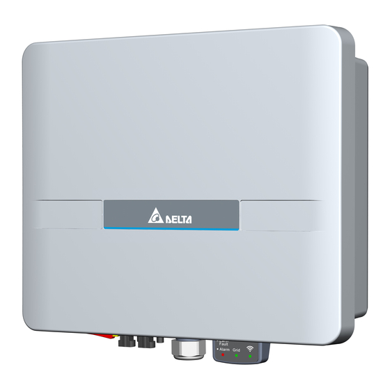
H2.5 / H3 / H3A / H4A _222 unit: mm Figure 3-1 : Dimensions of H2.5 / H3 / H3A / H4A / H5A 3.2 Function Introduction The Inverter’s exterior is shown in Figure 3-2. The description for individual objects can be found in sections 3.2.1. -
Page 12: Led And Button
Product Overview 3.2.1 LED and Button Figure 3-3 : LED and Button Table 3-1 : LED and Reset button function Action Status Flash:100ms On, 100ms Off Insulation Alarm Steady on Error or Fault. (see Chapter 9.1) Flash:100ms On, 100ms Off Default Country Setting Grid Flash:1s On, 1s Off... -
Page 13: Inverter Comparison
3.3 Inverter Comparison The DC switch is only presented in the 210/220/222 models. Model series 211/221 does not have the DC switch. _220 _221 (No DC switch) _220 _221 H2.5 H2.5 _210 _211 (No DC switch) _210 _211 (No DC switch) -
Page 14: 4 Installation
Installation 4 Installation 4.1 Installation Location The inverter can be installed in indoors / outdoors. WARNING ! Do not install the unit near or on flammable surfaces. Mount the unit tightly on a solid/smooth surface. CAUTION ! The unit should not be installed in direct sunlight. 4.2 Mounting This unit is designed to be wall-mounted. - Page 15 Installation ① Φ6.0*6 22.5 37.5 unit: mm ② ③ Figure 4-1 : Attaching the mounting bracket for H2.5 / H3 / H3A / H4A / H5A Figure 4-2 : Correct and incorrect installation illustration...
- Page 16 Installation Please ensure the spacing requirement to allow for sufficient convective cooling. It is essential to ensure sufficient space for product operation as shown in Figure 4-3. Single inverter >30cm >10cm >10cm >50cm Plural inverters >30cm >30cm >30cm >30cm >30cm >50cm >50cm >30cm...
-
Page 17: 5 Wiring
1. Ensure voltage values and polarities are correct. 2. When grounding the solar array positive or negative terminal, an isolation transformer is required due to the H2.5 / H3 / H3A / H4A / H5A not having galvanic isolation between the DC-input and AC-output. -
Page 18: Ac Grid Connection : L + N + Pe
30 mA (recommended) should be used. RCD of other specifications can also be used according to local standard. 5.2.1 Required protective devices and cable cross-sections 5.2.1.1 AC plug of H2.5 / H3 / H3A / H4A / H5A / H5A _220 _221... -
Page 19: Ac Plug Of H5A
Wiring Screw connection : Tightening torque typ. 4+1 N.m Detail Figure 5-2 : AC plug illustration (96.031.4154.3 01K, Wieland Electric GmbH) 5.2.1.2 AC plug of _222 Power rating Upstream AC circuit breaker 5 kVA _222 Table 5-2: Recommended upstream protection The AC plug provided with the inverter has the following technical characteristics: Technical data / IP68 (2 m, 24 h) - Page 20 Wiring Read and follow the instructions delivered with the AC plug. The AC plug delivered with the inverter can be used with flexible or rigid copper cable. When calculating the cross section of the cable, consider: ● material used ● thermal conditions ●...
-
Page 21: Dc Connection (From Pv Array)
PV array is OFF. CAUTION ! The maximum open circuit voltage of the PV Array must not exceed 500Vdc(H2.5) / 600Vdc (H3 / H3A / H4A / H5A). NOTE The isolator installed between the PV Array and inverter must meet the rating of voltage higher than this device’s maximum input voltage. -
Page 22: Dc Connector Of H5A
Wiring DC connectors on DC plugs for DC cable the inverter Multi-Contact 3–6 32.0010P0001-UR 1,5/2,5 5,5–9 32.0012P0001-UR DC– 3–6 32.0014P0001-UR 5,5–9 32.0016P0001-UR 3–6 32.0011P0001-UR 1,5/2,5 5,5–9 32.0013P0001-UR 3–6 32.0015P0001-UR 5,5–9 32.0017P0001-UR Table 5-3 : MC4 connectors DC wiring polarities have two components, Plus and Minus, which are shown in Figure 5-4. -
Page 23: Pe Connection
Wiring Description Specifications contact size 2.5mm² / 14AWG 4mm² / 12AWG 6mm² / 10AWG rated current (TUV) 25A @85˚C 35A @85˚C 45A @85˚C Table 5-4 : H4 connectors DC wiring polarities have two components, Plus and Minus, which are shown in Figure 5-5. -
Page 24: 6 Active/Reactive Power Control And Lvrt (Optional)
& generation limit function of the inverter. Meanwhile, the inverters setting can be viewed in a read-only mode for verification purpose. Please contact Delta local service for the password if request. Read Only... -
Page 25: Main Information
Active/Reactive Power Control and LVRT (Optional) 6.2 Main Information After select “Local Monitoring” and connect to the inverter, please select “INFO” sheet on the top row. The information including Serial Number, Model Name, FW version and etc. can be found in this page. -
Page 26: Country Setting And Grid Protection Setting
To check the country setting and grid protection setting, please access to “Local Setting” on the top row, select “Grid/VSG/ATS Setting” and “Grid Setting”. Please contact Delta local service for the access code to change the parameters in this page. -
Page 27: Active Power Control
Active/Reactive Power Control and LVRT (Optional) 6.4 Active Power Control 6.4.1 Grid protection settings The setting of this function can be found in the “Grid Setting” page, please refer to previous sub-chapter for the instruction to access to this page. Installers can adjust settings to meet the requirements from the grid operator. -
Page 28: P(U) Control
Active/Reactive Power Control and LVRT (Optional) 6.4.2 P(U) Control According to AS/NZS 4777.2:2020: The volt–watt response mode varies the output power of the inverter in response to the voltage at its terminal. The inverter should have the volt–watt response mode. This mode is enabled by default. -
Page 29: Power Vs. Frequency
Active/Reactive Power Control and LVRT (Optional) 6.4.3 Power vs. Frequency According to VDE-AR-N 4105 (5.7.3.3): At frequencies between 50.2Hz and 51.5Hz, all adjustable power generation systems shall reduce (for frequency increase) or increase (for frequency decrease) the active power Pm generated instantaneously (at the time of exceeding the mains frequency 50.2Hz;... - Page 30 Active/Reactive Power Control and LVRT (Optional) Frequency variation withstand limits Decrease in Lower limit of Upper limit of Increase in Inverter frequency continuous continuous frequency response operation operation response response Lower limit Hz range (fLLCO) Hz range (fULCO) Hz Upper limit Allowed range 49.5 - 49.9 50.1 - 50.5...
-
Page 31: Reactive Power Control
Active/Reactive Power Control and LVRT (Optional) 6.5 Reactive Power Control The setting of this function can be found in the “Grid Setting” page, please refer to previous sub-chapter for the instruction to access to this page. 6.5.1 Fixed Power Factor cosφ (VDE-AR-N 4105,CEI 0-21) Users can set the power factor from Cap 0.8 to Ind 0.8 (inverter would stop reactive power control if output power is below 20% rated power). -
Page 32: Cosφ(P) (Vde-Ar-N 4105,Cei 0-21)
Active/Reactive Power Control and LVRT (Optional) 6.5.2 cosφ(P) (VDE-AR-N 4105,CEI 0-21) Once user enables this method, the inverter will deliver reactive power according to output active power at that moment. Figure 6-2 is an example. cos φ Upper limit Cap 0.9 P/ Pn lower limit Ind 0.9... -
Page 33: Reactive Power/ Voltage Characteristic Q(U)(Cei 0-21)
Active/Reactive Power Control and LVRT (Optional) 6.5.4 Reactive Power/ Voltage Characteristic Q(U)(CEI 0-21) Once the user enables this method, the user can set Q vs. Grid voltage operation curve as in Figure 6-3. Table Q(U) response default set-point values Region Default value Voltage 207 V... -
Page 34: Low Voltage Ride Through (Lvrt)
Active/Reactive Power Control and LVRT (Optional) 6.6 Low Voltage Ride Through (LVRT) According to CEI 0-21, 8.5.1 To avoid undue separation from the network if voltage dips occur, a generation system with over 6 kW total power must be able to comply with certain functional requirements, which are known as LVRT (Low Voltage Ride Through) in international literature. -
Page 35: Export Limit And Generation Limit
Active/Reactive Power Control and LVRT (Optional) 6.7 Export Limit and Generation Limit As per AS4777.2:2020, there are two generation control functions required, including generation limit control and export limit control. To change the setting of both control, please access to the “local setting” page, select “function setting”... -
Page 36: Digital Input
To implementation of power management, the digital input interface receives the specifications of the network operator via a ripple control receiver or a DRED. H2.5/H3/H3A/H4A/H5A can access these command via DC1 _100 • Germany : The active power limitation in the stages 0%, 30%, 60% and 100% •... -
Page 37: Function Port Of H5A
Active/Reactive Power Control and LVRT (Optional) 6.9 Function Port of H5A _222 * Screw torque required for assembling: 8±2 kgf-cm Dry contact Digital input Power meter 6.9.1 Installation of the Rubber Washer ③ ② ① ④ Φ6.0mm x3 (1) Loosen the front cover ① counterclockwise. (2) Remove the rubber washer ②... -
Page 38: Digital Input
Active/Reactive Power Control and LVRT (Optional) 6.9.2 Digital Input To implementation of power management, the digital input interface receives the specifications of the network operator via a ripple control receiver. • Australia and New Zealand: The inverter support the demand response mode (DRMs). DRM 0 - Operate the disconnection device. -
Page 39: Dry Contact Connection
Active/Reactive Power Control and LVRT (Optional) 6.9.3 Dry Contact connection Provide single set of Dry Contact. The function can be customized by users. The dry contact port can withstand with 250Vac/28Vdc/9A, and suitable electric wire is 0.2-1.5 mm². 6.9.4 Power meter Connecting the current sensor in the following steps (1) Attach a current sensor to the L cables of the main earth leakage circuit breaker. - Page 40 Turning the PV inverter on/off 7 Turning the PV inverter on/off WARNING ! The internal temperature may exceed over 70°C while operating. To avoid injury, do not touch the surface of the inverter whilst the unit is in operation. After installation, please ensure the AC, the DC and communication connection are correct.
- Page 41 Turning the PV inverter on/off 7.1.3 Starting up the Inverter ATTENTION Due to the variety of installation environments, installation of the unit and start-up procedures must be carried out by an accredited technician. Incorrect settings may cause the inverter to malfunction. 1.Switch on the PV Array switch and DC switch (with DC switch model) to connect PV Array.
- Page 42 Maintenance 8 Maintenance In order to ensure normal operation of the inverter, please check the unit regularly. Check that all terminals, screws and cables are connected and appear as they did upon installation. If there are any impaired or loose parts, please contact your solar installer immediately.
- Page 43 Error Message and Trouble Shooting 9 Error Message and Trouble Shooting Table 9-1 : Error Message Error Message Possible cause Action 1. Check the utility frequency on the 1. Actual utility frequency is higher inverter terminal than the OFR setting E01: OFR 2.
- Page 44 3. Detection circuit malfunction the inverter 1. Modify the solar array configuration 1. Actual Solar voltage is over and make the Voc less than 510Vdc (H2.5) or 500Vdc (H2.5) or E30: OVR(PV) 560Vdc (H3/ H3A/ H4A/ H5A) 550Vdc (H3/ H3A/ H4A/ H5A) 2.
- Page 45 Error Message and Trouble Shooting Fault Message Possible cause Action 1. Check the auxiliary circuitry inside the inverter 1. Auxiliary power circuitry malfunction F15: HW ADC1 2. Check the detection circuit inside 2. Detection circuit malfunction the inverter 1. Check the auxiliary circuitry inside the inverter 1.
- Page 46 1. Driver for boost is defective 2. Modify the solar array setting, 2. Voc of PV array is over and make the Voc less than F35: 510Vdc (H2.5) or 500Vdc (H2.5) or HW Bus OVR 560Vdc (H3/ H3A/ H4A/ H5A) 550Vdc (H3/ H3A/ H4A/ H5A) 3.
- Page 47 De-Commissioning 10 De-Commissioning De-Commissioning Procedure: If necessary to put the device out of operation for maintenance and/or storage, please follow the instructions below. WARNING ! To avoid injuries, please follow this procedures 1. Switch off AC circuit breaker to disconnect from electricity grid. 2.
- Page 48 Max. inverter backfeed current to the array Startup voltage 35 Vdc Input connection MC4, 1 pairs MC4, 2 pairs H4, 2 pairs 1: H2.5 / H3 / H3A / H4A / H5A / H5A : The product is with DC switch _210...
- Page 49 Technical Data H2.5 _210 _210 _220 _220 _220 Model _222 H2.5 _211 _211 _221 _221 _221 DC Switch parameters (Solar side) Insulation voltage (Ui) 850 V 1200 V Rated impulse withstand 8 kV voltage(Uimp) Suitability for isolation Isolating device Rated operational current...
- Page 50 IEC 61000-4-6 PFMF IEC 61000-4-8 3: (a) H2.5 : 2.49kVA max. for Australia, New Zealand (AU / NZ) (b) H3 / H3A : 2.99kVA max. for Australia, New Zealand (AU / NZ) (c) H5A : 4.6kVA max. for Germany (DE) (d) H4A/ H5A : 3.68kVA max.
Need help?
Do you have a question about the H2.5 and is the answer not in the manual?
Questions and answers