Delta M70A 260 Operation And Installation Manual
Grid-tie transformerless solar inverter
Hide thumbs
Also See for M70A 260:
- Installation and operation manual (200 pages) ,
- Installation and operation manual (166 pages) ,
- Operation and installation manual (88 pages)

Related Manuals for Delta M70A 260


Summary of Contents for Delta M70A 260
- Page 1 The power behind competitiveness Grid-tie Transformerless Solar Inverter M70A / M50A _260 _260 Operation and Installation Manual www.deltaww.com...
-
Page 3: Table Of Contents
Contents ......... . . 1 Safety . - Page 4 4.3 Delta Function Setting ........
- Page 5 Figure ........Figure 2-1: Components .
- Page 6 ....... . . Figure 4-6: Steps of set country ....... . . Figure 4-7: False of set country .
- Page 7 Table ........Table 2-1: Packing list .
-
Page 8: 1 Safety
DELTA ELECTRONICS, INC. Service engineers and end users may not divulge the information contained herein or use this manual for purpose other than those strictly connected with correct use of the product. -
Page 9: General Safety
This user manual provides important instructions for Delta grid-tie transformerless solar inverter. The product is designed, tested, verified, and certified according to international safety requirements, certifications, and standards but precautions must be observed when installing and operating the product. -
Page 10: Symbols
Safety 1.2.2 Symbols This section describes the definition of the symbols in this manual. In order to prevent both personal injury and property damage, and to ensure long-term operation of the product, please read this section carefully and follow all the safety instructions while you use the product. DANGER! - This warning indicates an immediate hazard which will lead to death or serious injury. - Page 11 Safety INFORMATION - An exclamation mark enclosed in a double circle indicates additional important information is contained in the following section and the user should follow the instructions to prevent any hazards. DANGER : ELECTRICAL HAZARD!! - This warning indicates an immediate electrical hazard that unheeded can lead to death or serious injury.
-
Page 12: 2 Introduction
The user manual is valid for the following device types: • M70A _260 • M50A _260 This user manual must be followed during installation, operation, and maintenance. Delta reserves the right to make modifications to the content and technical data in this user manual without prior notice. -
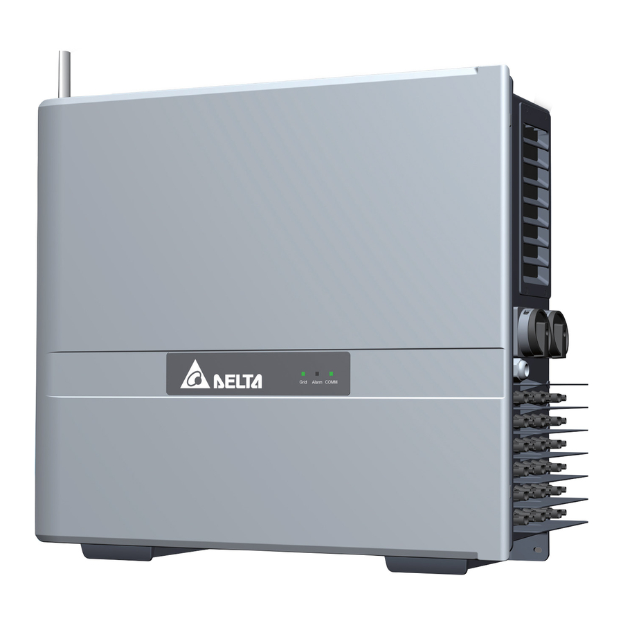
Page 13: Product Overview
Figure 2-1: Components Table 2-1: Packing list M70A / M50A _260 _260 Object Description Delta Solar Inverter 1 pc Solar inverter Important instructions for solar inverter. 1 pc User Manual Safety instructions should be followed during installation and maintenance. Wall mounting bracket... - Page 14 Introduction ⑤ ⑥ ⑨ ⑩ ⑪ M70A _260 ① ② ③ ⑮ ⑦ ⑮ ⑧ ⑫ ⑮ ⑭ ⑤ ⑥ ⑨ ⑩ ⑪ M50A _260 ① ② ④ ⑮ ⑦ ⑮ ⑧ ⑬ ⑮ Figure 2-2: Overview Table 2-2: Overview description Component Component Component...
- Page 15 Introduction Figure 2-3 below, shows the certification and rating label. Table 2-3 defines the symbol markings on this label. Figure 2-3: Rating label Table 2-3: Rating label explanation Symbol Definition Danger to life through electric shock Potentially fatal voltage is applied to the inverter during operation. This voltage persists even 60 seconds after disconnection of the power supply.
- Page 16 Introduction M70A M50A _260 _260 Figure 2-4: External/ internal view...
- Page 17 Introduction M70A _260 ④ ① ② ③ ⑦ ⑥ ⑤ M50A _260 ④ ① ② ③ ⑦ ⑥ ⑤ Figure 2-5: layout Table 2-4: layout description Component Component Component Communication module Type II DC SPD Internal grounding Internal fan 1 Type II AC SPD Internal fan 2 AC terminal...
-
Page 18: 3 Installation
Installation 3 Installation CAUTION ! - In some locations, mounting the inverter in direct sunlight may cause the inverter to enter a thermal derating mode. To eliminate this concern, a shade structure over the inverter chassis may be necessary. WARNING ! - Do not install the unit near or on flammable surfaces. -
Page 19: Unboxing & Review
Installation 3.1 Unboxing & Review Unpacking the case, please follow the order of Figure 3-1. It could be transported by 2 people (Figure 3-2) . For ground mount installation It is recommended to install the grounded brackets first at this step. For detailed installation methods, Need more than please see section 3.2.2. - Page 20 Installation Prohibit to force with Prohibit to force with Prohibit to force with fan shutter. DC connector. DC switch. Prohibit to force with AC gland. Figure 3-2: Handle position for handling...
-
Page 21: Mechanical Installation
Installation 3.2 Mechanical Installation This unit is designed to be wall-mounted per Section 3.2.1 or ground mounted Section 3.2.2. 3.2.1 Vertical Wall Mount Refer to Figures 3-4 through Figures 3-9. 1. Ensure the surface to which the unit is to be mounted is sufficiently strong enough to carry the weight. - Page 22 Installation 699 mm 264 mm Figure 3-3: Inverter dimensions unit: mm Figure 3-4: Mounting bracket dimensions...
- Page 23 Installation Positions for least amount of mounting bracket screws Figure 3-5 : Positions of mounting screws >280mm Figure 3-6: Permitted mounting positions...
- Page 24 Installation Figure 3-7: Prohibited mounting positions Wall > 990mm > 320mm > 415mm > 840mm > 700mm Inverter #1 Inverter #2 > 1300mm > 400 > 708mm > 570mm > 690mm* * If wiring without door. (To remove the door, please refer to section 3.3) Figure 3-8: Required mounting clearances...
- Page 25 Installation Wall Without Clapboard >200mm >200mm >300mm >600mm >300mm >60mm * >60mm * * If the installation location has a risk of flooding or accumulated snow, please raise the appropriate height of the inverter. Clapboard Install Clapboard dimension 200mm >830mm >150 >150 >380mm...
-
Page 26: Ground Mount (Option)
Installation 3.2.2 Ground Mount (Optional) ATTENTION - Ensure the grounded base is strong enough to hold the weight of the inverter. Grounded Bracket kit is an optional part, please contact the customer service center for the detail. 1. Fix the grounded brackets to the bottom of the inverter as Figure 3-10. 2. - Page 27 Installation Φ12.5 mm 310 mm 458 mm height * * If the installation location has a risk of flooding or accumulated snow, please raise the appropriate height of the inverter. Figure 3-11: To secure inverter grounded brackets to ground-mounting base...
-
Page 28: Door
Installation 3.3 Door In order to ensure the normal long-term operation of the inverter, please follow the procedures in Section 5.1 to open and close the door. If the installation space is too narrow for the wiring operation, please remove the door according to Figure 3-12. -
Page 29: Ac Grid Types And Connections
Installation 3.4.1 AC Grid Types and Connections ATTENTION The default AC Grid connection is 3Ø-3W. It can also connect 3Ø-4W with Neutral (N). The inverter will operate from the following grid connections without need of an external transformer: TNC system TNC-S system 230/400V 230/400V... - Page 30 Installation M70A / M50A support Cu stranded, Cu flexible conducor, Al stranded _260 _260 wire, aluminum solid (include sector wire) Cu stranded Cu flexible wire Al stranded Aluminum solid (need press with terminal) (sector) * • Cu: The Cu flexible wire need stamp with terminal, for the other model wiring with bear wire is available.
-
Page 31: Ac Side -Prewire Set-Up
Installation Table 3-1: Cable size comparison table M70A Sizes of Cables (mm) Torque (N•m) Dimension of P (mm) 51-57 2550 mm 43-50 1962 mm 36-43 1450 mm 30-36 1017 mm 26-30 706 mm M50A Sizes of Cables (mm) Torque (N•m) Dimension of P (mm) 30.8-44.7 1570 mm... -
Page 32: Ac Wiring
Installation 3.4.5 AC Wiring Refer to Figure 3-13 in Section 3.4 for the procedure to prepare AC conductors for connection to the AC terminals. Ensure the AC conductors used are sized to the correct ampacity per NEC or other local code. After inserting conductor, torque terminal nut by M70A: 31 N •... -
Page 33: Electrical Installation For Dc Wiring
Installation 3.5 Electrical Installation for DC Wiring DANGER : ELECTRICAL HAZARD!! - PV array converts sunlight into electric power with high DC voltage and high DC current which can cause dangerous electrical shock hazard! - Use an opaque material to cover the PV array before wiring or cabling. - Ensure the correct polarities are connected when DC cabling is applied. -
Page 34: Dc Wiring Installation
Figure 3-17. • After DC Wiring installing, insert the protective frame for DC connector and the method is shown in Figure 3-18. ATTENTION - According to different local regulations, if the external string fuse is required, please contact Delta dealers. MDFU-10-66-20-H4... - Page 35 Installation M70A M50A _260 _260 SWITCH 1 SWITCH 2 SWITCH 1 SWITCH 2 Figure 3-17: location of H4 connectors to connect array wiring (DC)
- Page 36 Installation PUSH PUSH Install protective frames before plug in DC connectors. Figure 3-18: Installation methods for protective frame...
-
Page 37: Equipment Grounding
Installation 3.5.2 Equipment Grounding To ground the inverter, please crimp the grounding wire to ring terminal lug and fix it on the grounding point shown as figure 3-19. Screw torque: M6/ 3.9 N•m Figure 3-19: Mount the equipment grounding... -
Page 38: Antenna
Figure 3-20 ~ 3-22. ATTENTION - Always keep nut and screws properly tightened on the case. Water leakage may cause serious damage. Contact DELTA service when lack for nut and screws. - Store the nut for spare usage. Antenna Location Save the nut after antenna installed. - Page 39 Installation >20 cm There must be no obstacles within 20 cm around the antenna. Keep antenna pointing upright. Figure 3-21: Attentions of installing antenna...
- Page 40 Installation 1. Turn the antenna counterclockwise by about 45 degrees. 2. Put on the antenna bracket. 3. Turn the antenna to the proper position. 4. Tighten the 3 screws to antenna bracket. ① ② ③ ④ Screw locations * Screw torque: M4 / 0.98 N • m Figure 3-22: Install antenna bracket ATTENTION - Please refer Data Collector manual for connection of Data Collector.
-
Page 41: Communication Module Connections
Installation 3.7 Communication Module Connections The communication module is shown in Figure 3-23. It provides VCC, RS-485, dry contact, EPO, and Digital Input terminals for use in various applications. Details for each are presented below. There's a 12VDC source between VCC & GND for use with external device. VCC *1 &... - Page 42 Installation Please refer to the chapter 5.1 and open the door, the communication module is at the circle that is shown in Figure 3-24. Figure 3-24: Location and access to Communication Module...
-
Page 43: Rs-485 Connection
Installation 3.7.1 RS-485 Connection The pin definition for the RS-485 terminal block is shown in Table 3-2. - Pins 1 and 2 provide a 12VDC / 0.5A bus for use with accessories. - Pins 3 and 5 are both connected to the DATA+ input. - Pins 4 and 6 are both connected to the DATA - input. - Page 44 Installation Terminal Resistor 120Ω(1/2W) DATA+ to DATA- RS485/USB RS485/RS232 Figure 3-25: Multiinverter connection illustration Termination switch Table 3-3: Bus Termination switch settings Switch 1 Terminal Resistor ON Terminal Resistor OFF...
-
Page 45: Epo Function & Digital Input
3.7.2 EPO Function & Digital Input The communication module has an Emergency Power Off function (EPO). Users can customize EPO function in APP or Delta Solar System (DSS). VCC K0 K1 K2 K3 K4 K5 K6 Figure 3-26: EPO function terminal block Once enabled, the EPO function can be used to turn off the inverter via a NO relay contact connected across terminal [VCC &... -
Page 46: Dry Contact Connection
Installation 3.7.3 Dry Contact Connection M70A_260 and M50A provide a dry control contact pair that may be used to _260 control external devices based on the status of operation of the inverter. The terminal block for this function is shown in Figure 3-27. The terminals marked in the figure identify the dry contact connection. -
Page 47: On-Site Insulation Test
Installation 3.8 On-Site Insulation Test For customers who want to do on-site insulation test, please make sure: 1. The DC switches are in “OFF” position. 2. Apply one probe to the positions shown in Figure 3-28, the other to the ground. It might cause damages to the inverter if probes are applied to inappropriate positions. -
Page 48: 4 Commissioning
Commissioning 4 Commissioning CAUTION : HOT SURFACES, DO NOT TOUCH! - Use care to avoid hot surfaces when operating the product! - Do not perform any task until the unit cools down or appropriate personal protection gear is worn. 4.1 Display Operation Introduction M70A_260 and M50A with 3 LEDs allow visual display of the inverter’s data _260... -
Page 49: Auto Id Commission Tool
Commissioning 4.2 Auto ID Commission Tool The Auto ID function could set all inverter IDs at monitoring center after wiring RS-485. ATTENTION Please download the software from the following website: https://mydeltasolar.deltaww.com/dl_installer_guide.php?f=autoid 4.2.1 Auto ID Setting Open the software 1. Select COM Port and click 2. - Page 50 Commissioning The numbers of ID setting less than amounts of inverter, status show False. The numbers of ID setting more than amounts of inverter, status show False. Figure 4-3: False of auto ID setting by tool...
-
Page 51: Set Id
Commissioning 4.2.2 Set ID To adjust the ID order, please follow the settings below. 1. Enter the ID you want to change . 2. Click to complete. Figure 4-4: Steps of set ID The wrong ID setting of overlapping. Figure 4-5: False of set ID... -
Page 52: Set Country
Commissioning 4.2.3 Set Country Set country by the AUTO ID. 1. Entry the local country ID number. 2. Click the to complete country setting. Figure 4-6: Steps of set country Enter as a country that does not exist. Figure 4-7: False of set country... -
Page 53: Synchronize Time
Commissioning 4.2.4 Synchronize time Synchronize time by Auto ID tool. Click the to complete time setting. Figure 4-8: Steps of synchronize time Interference problem make sync time fail, please try again. Figure 4-9: False of synchronize time... -
Page 54: Delta Function Setting
Commissioning 4.3 Delta Function Setting Delta offers two setting tools: DSS (Delta Solar System Software) and APP (MyDeltaSolar) Function Active power control Q(U) control (volt-var control) P-F control (watt-frequecy control) Q by night(Q setting 24/7) P(U) control (volt-watt control) Anti-PID Fixed cosφ... -
Page 55: 5 Maintenance
Maintenance 5 Maintenance Please check the unit regularly. If there are any impaired or loose parts, please contact your solar installer. Ensure that there are no fallen objects in the path of the heat outlet. WARNING ! - Prior to beginning any maintenance procedures outside AC breaker and DC switch off to avoid risk of electrical shock! 5.1 Open and Close the Door In order to guarantee proper long-term operation of the inverter, the following... - Page 56 Maintenance ① ② * Screw torque: M4 / 0.98 N•m ③ ⑤ ② ④ ① Figure 5-1: Open and close the door...
- Page 57 Maintenance ATTENTION - After opening the door, please make sure the door is fixed by hexagon driver to avoid strong wind breaking it. Figure 5-2: To secure door by hexagon driver...
-
Page 58: Replacement Of Surge Protection Devices (Spd)
Maintenance 5.2 Replacement of Surge Protection Devices (SPD) M70A_260 and M50A_260 have the surge protection device (SPD) at both AC and DC side as shown in Figure 5-3. AC SPD DC SPD M70A M50A _260 _260 Figure 5-3: AC and DC SPD modules... - Page 59 Maintenance Surge protection devices (SPD) are designed to protect sensitive circuit elements of the inverter from damage caused by lightning and other electrical transients/surges, as such they are sacrificial components and periodically, may need replacement. The SPDs are located in the inverter. If a warning message “AC Surge”...
- Page 60 Maintenance • Accessing the door 1. Switch DC and AC power off and wait until LED display turns off. 2. To access the door, use procedure found in Section 5.1.1 Do not leave the door opened for long periods of time. •...
- Page 61 Maintenance DC SPD AC SPD * Screw torque: 0.8 N•m Please use manual pre-tighten before attaching. Figure 5-5: Steps of changing SPDs...
- Page 62 Maintenance AC SPDs * A: Screw torque 2.45 N •m * G: Screw torque 0.8 N • m M50A _260 M70A _260 Figure 5-6: Remove wirings as connectors of AC SPD *Wi-Fi (option) DC SPDs * A: Screw torque 2.45 N • m * G: Screw torque 0.8 N •...
-
Page 63: External String Fuse
Periodic fan and filter cleaning is required to insure long life and reliability. - The time period between cleanings depends on the quality of the environment. - Under normal duty use, Delta recommends smart fans and filters be cleaned every 4 months - For very dusty locations, it may be necessary to clean the fans and filters quarterly or monthly. -
Page 64: Location Of Failure Fan For M50A_260
Maintenance 5.4.1 Location of failure fan for M50A_260 If the Error-code comes "Fan Fail", please refer to the corresponding code shown on DSS and procedure in following chapters to remove the fan. Internal External Figure 5-9: The corresponding fan location to the fan fail code on DSS DANGER : ELECTRICAL HAZARD!! - Prior to beginning any maintenance procedures outside AC breaker and DC switch off to avoid risk of electrical shock! -
Page 65: Power Module (Pm) Fan Tray
Maintenance 5.4.2 Power Module (PM) Fan Tray The inverter electronics are convection cooled. The primary equipment used for this function consists of a fan tray located in a plenum within the inverter. The PM electronics are isolated, and heat is transferred to the plenum airflow via a large heatsink. - Page 66 Maintenance * Screw torque required for assembling: 0.98 N•m ① ② snap-fit ③ * Screw torque required for assembling: 0.6 N•m Figure 5-10: Disassembling fan tray from PM chassis...
-
Page 67: Internal Fan 1
Maintenance 5.4.3 Internal Fan 1 If the warrning "Fan Fail- Internal F01" show on the DSS / APP, please follow the procedure below to remove Internal Fan 1. (1) Remove the B cover. (2) Loosen two self-retaining screws shown in Figure 5-11 and remove the fan cabinet. - Page 68 Maintenance M70A M50A _260 _260 * Screw torque required for assembling: 0.8 N•m Figure 5-12: Take off the internal fan 1 M70A M50A _260 _260 * Screw torque required for assembling: 0.6 N•m Figure 5-13: Replace with a new fan...
-
Page 69: Internal Fan 2
Maintenance 5.4.4 Internal Fan 2 If the warrning "Fan Fail- Internal F00" show on the DSS / APP, please follow the procedure below to remove Internal Fan 2. (1) Loosen two self-retaining screws shown in Figure 5-14 and remove the fan cabinet. - Page 70 Maintenance * Screw torque required for assembling: 0.8 N•m Figure 5-15: Take off the internal fan 2 * Screw torque required for assembling: 0.6 N•m Figure 5-16: Replace with a new fan...
-
Page 71: Commissioning
Maintenance 5.5 De-Commissioning When necessary to remove the inverter from active operation for maintenance or replacement, follow the instructions below. DANGER : ELECTRICAL HAZARD!! To avoid serious injury, please follow the procedure below. - Switch off external AC circuit breaker or switch to disconnect the electrical grid from the inverter chassis. - Page 72 Maintenance CAUTION : HOT SURFACES, DO NOT TOUCH ! - Use care not to touch hot surfaces if the inverter is just shutting down. - Do not perform any task until the product cool down sufficiently. CAUTION : POSSIBILE INJURY ! M70A weighs more than 69 kg / M50A weighs more than 64 kg.
-
Page 73: 6 Error Message And Trouble Shooting
Error Message and Trouble Shooting 6 Error Message and Trouble Shooting While Delta Electronics endeavors to build electronic products to very high standards of reliability, there will arise instances where the inverter may not operate properly. When such a condition is encountered, please follow the instructions in the Troubleshooting Guide (Tables 6-1, 6-2, and 6-3) to attempt to clear the fault. -
Page 74: Fault Codes (Inverter Fault)
Error Message and Trouble Shooting 6.2 Fault Codes (Inverter Fault) Table 6-2A: Fault Codes (inverter fault) & Messages Message Description Action Contact customer service for Injection Utility waveform is abnormal technical support (F01,F02,F03) Temperature One of inner ambient NTC and Check the installation ambient and High inverter module NTCs is over... - Page 75 Error Message and Trouble Shooting Table 6-2B: Fault Codes (inverter fault) & Messages Message Description Action 1. Check the insulation of Solar inputs Ground Cur. Insulation problem of PV array High 2. Contact customer service for to ground (F24) technical support 1.
-
Page 76: Warning Codes (Field Warning)
Error Message and Trouble Shooting 6.3 Warning Codes (Field Warning) Table 6-3A: Warning Codes (Field warning) & Messages Message Description Action DC Voltage Check the voltage connection to the Input voltage is under the limit inverter terminal (W01) 1. Check the installation ambient and environment 2. -
Page 77: 7 Technical Information
Technical Information 7 Technical Information Table 7-1A: Specifications Model M70A_260 M50A_260 DC Input Occasionally max. voltage 1100 V * Operating Voltage Range 200 - 1000 V MPP Voltage Range (Full Power) 460 - 900 V * 390 - 900 V * Start Voltage >... - Page 78 Technical Information Table 7-1B: Specifications Model M70A_260 M50A_260 Efficiency Peak efficiency 98.8 % 98.7 % 98.4 % 98.3 % Euro efficiency Information Communication Port RS-485 / SUB_1G / Wi-Fi (optional) Regulation IEC 62109-1/-2 VDE-AR-N 4110 EN 61000-6-2 NB/T 32004: 2018 EN 61000-6-3 GB/T 19964: LVRT VDE-AR-N 4105...
- Page 79 Technical Information Efficiency Output voltage at 400Vac Efficiency(%) Pn=70kW 100% 460V 600V 800V 100% Output Power (%) Efficiency(%) Pn=50kW 100% 390V 600V 800V 100% Output Power (%) Figure 7-1: Efficiency Curve...
- Page 80 Technical Information Power Derating Curve with Ambient Temprature Output voltage at 230Vac / 400Vac PF=1 P/Pn(%) Pn=70kW 110% 100% 90 % 460V 80 % 520V 600V 70 % 720V 800V 60 % 900V 50 % Ambient Temperature (°C) P/Pn(%) Pn=50kW 110% 100% 90 %...
- Page 81 Technical Information Power Derating Curve with Ambient Temprature Output voltage at 230Vac / 400Vac PF=0.9 P/Pn(%) Pn=70kW 110% 100% 90 % 80 % 460V 520V 600V 70 % 720V 800V 60 % 900V 50 % Ambient Temperature (°C) P/Pn(%) Pn=50kW 110% 100% 90 %...
- Page 82 Technical Information Apparent Power Derating Curve with Ambient Temprature Output voltage at 230Vac / 400Vac PF=0.9 S/Sn(%) Sn=70kVA 110% 100% 90 % 460V 80 % 520V 600V 70 % 720V 800V 60 % 900V 50 % Ambient Temperature (°C) P/Pn(%) Pn=50kW 110% 100%...
-
Page 83: Appendix: Assembly Note
Technical Information Appendix: Assembly Note ③ ④ ⑤ ① ② ⑥ Appendix-1: Assembly Note-1 Location Screw torque Filter 10 kgf-cm (0.98N• m) Fan Tray 6 kgf-cm (0.6N•m) Antenna 12 kgf-cm (1.2N•m) Antenna Bracket (M4) 10 kgf-cm (0.98N•m) Grounded Bracket 250 kgf-cm (24.5N•m) Grounding (M6) 40 kgf-cm (3.9N•m) - Page 84 Technical Information ③ ① ② ④ ⑤ H4CFC4D-MS H4CMC4D-MS Appendix-2: Assembly Note-2 Location Screw torque Conductor cross-section Internal Fan 2 Cover 8.0 kgf-cm (0.8N•m) Internal Fan 2 Tray 6 kgf-cm (0.6N•m) Internal Fan 1 Cover 8.0 kgf-cm (0.8N•m) Internal Fan 1 Tray 6 kgf-cm (0.6N•...
- Page 85 Technical Information ① ① ④ ⑤ ④ ⑥ ② ③ ③ ② ⑤ ④ Appendix-3: Assembly Note-3 NO Location Screw torque Conductor cross-section DC SPD board A: 25 kgf-cm (2.45N•m) G: 8.0 kgf-cm (0.8N •m) AC SPD board AC Cover 8.0 kgf-cm (0.8N•m) Toggle Latch 25 kgf-cm (2.45N•m)
- Page 88 5013289600 Version 01210108...
Need help?
Do you have a question about the M70A 260 and is the answer not in the manual?
Questions and answers