Table of Contents
Advertisement
Quick Links
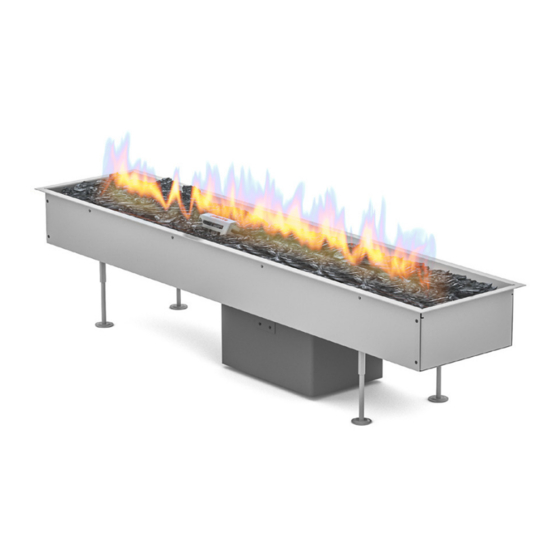
INSTALLATION MANUAL
GaLiO Insert #2
G20/G25 (Natural Gas) G30/G31 (Propane-Butane/Propane)
H
H1
H2
H3
L
L1
L2
L3
L4
D
D1
D2
[mm]
260
258,5
1,5
120
1027
944
43,5
43,5
240
230
205
160
Manufactured by
Planika Sp. z o.o.
Bydgoska 38
86-061 Brzoza
Poland
Copyright Planika Sp. z o.o.
www.planikafires.com
IG0098#01
19.02.2018
1
Advertisement
Table of Contents

Related Manuals for Planika GaLiO Insert 2


Summary of Contents for Planika GaLiO Insert 2
- Page 1 INSTALLATION MANUAL GaLiO Insert #2 G20/G25 (Natural Gas) G30/G31 (Propane-Butane/Propane) [mm] 258,5 1027 43,5 43,5 Manufactured by Planika Sp. z o.o. Bydgoska 38 86-061 Brzoza Poland Copyright Planika Sp. z o.o. www.planikafires.com IG0098#01 19.02.2018...
-
Page 2: Table Of Contents
Connection and replacement of the gas cylinder (LPG version) ..............16 Adapters for the gas cylinder connection (LPG version) ................. 18 Pressure regulator replacement (LPG version) ....................19 TECHNICAL SPECIFICATION ............................. 20 MANUFACTURER’S CONTACT DETAILS ........................21 Copyright Planika Sp. z o.o. www.planikafires.com IG0098#01 19.02.2018... -
Page 3: Introduction
In case of noticing any sort of gas leaks the fireplace as well as the main valve of the gas cylinder need to be • turned off. After use turn off the gas cylinder valve. • Copyright Planika Sp. z o.o. www.planikafires.com IG0098#01 19.02.2018... -
Page 4: Safety Instruction Regarding The Use Of The Gas Cylinder
1x 4 metre rubber gas linkage – installed (only LPG version) • 1x pressure regulator (37mbar) – installed (only LPG version) • 1x Euro Set (only LPG version) • 1x installation manual • 1x user’s manual • Copyright Planika Sp. z o.o. www.planikafires.com IG0098#01 19.02.2018... - Page 5 10 cm (Photo 2). Photo 2 If all the points were completed according to the instruction the gas cylinder can be • now connected. Copyright Planika Sp. z o.o. www.planikafires.com IG0098#01 19.02.2018...
-
Page 6: Montage
Additionally, Planika materials doesn't recommend placing heat-sensitive objects above the fireplace as it may shorten their lifetime. Planika will not be responsible for any damage caused by high temperature affecting objects installed above the fire. Ventilation grate or slot with ventilation... - Page 7 It is not permitted to use a device which is not housed in some way. • Copyright Planika Sp. z o.o. www.planikafires.com IG0098#01 19.02.2018...
-
Page 8: Directions Of How To Design A Housing For The Fireplace
Make the cavity for the insert according to the below outline. When preparing the cavity make sure the surface • on which the insert is placed is well-levelled as there is no option of levelling out the insert. Ventilation grate or slot with ventilation area of minimum 150cm2 Copyright Planika Sp. z o.o. www.planikafires.com IG0098#01 19.02.2018... -
Page 9: Montage Involving Use Of Adjustable Supports
In this montage variant the insert is using the help of supports attached to the device. An appropriate space • needs to be provided around the fireplace allowing its trouble-free installation and providing correct circulation inside the fireplace. Ventilation grate or slot with ventilation area of minimum 150cm2 Copyright Planika Sp. z o.o. www.planikafires.com IG0098#01 19.02.2018... - Page 10 • visible during normal use of the device. In case of the cavity being deeper than the height of the device on supports Planika permits a solution where the • device is set on a stable and levelled plinth placed on the bottom of the cavity. The top surface of the plinth should be H + 10 mm away from the top of the surface of the housing.
-
Page 11: Control Panel And Gas Cylinder Montage
4.2 Control panel and gas cylinder montage 4.2.1 Montage of the gas cylinder. The control panel along with the gas valve is inseparably connected with the GaLiO Insert fireplace through • elastic gas linkage and the ignition linkage. Copyright Planika Sp. z o.o. www.planikafires.com IG0098#01 19.02.2018... - Page 12 The gas linkage attached to the device allows to place the gas cylinder maximally 3 metres away from the • connected control panel, however it cannot be placed nearer to the device than 1,5 metres. Copyright Planika Sp. z o.o. www.planikafires.com IG0098#01...
- Page 13 The control panel may be installed in a horizontal or vertical position with the use of angles attached to it. Copyright Planika Sp. z o.o. www.planikafires.com IG0098#01 19.02.2018...
- Page 14 • If in future a need arises of having to take the insert out of the housing it may only be done when the device is turned off and cooled down and the valve on the gas cylinder is closed. • Keep this instruction manual for the lifetime of the device. Copyright Planika Sp. z o.o. www.planikafires.com IG0098#01...
-
Page 15: Possible Housing Variants
In this case one has to put an emphasis on safety measures and disallow children, unauthorised persons and animals to have a direct contact with the fire. Copyright Planika Sp. z o.o. www.planikafires.com IG0098#01 19.02.2018... -
Page 16: Installation Of The Gas Linkage
In case of using a connector with a thread regulator of an old type put a special emphasis on checking if the connecting nut has been tightly fastened with the help of wrench. Copyright Planika Sp. z o.o. www.planikafires.com IG0098#01... - Page 17 After removing the leak one may open the gas cylinder valve again. • Copyright Planika Sp. z o.o. www.planikafires.com IG0098#01 19.02.2018...
-
Page 18: Adapters For The Gas Cylinder Connection (Lpg Version)
When the thread of the installed pressure regulator does not fit into the thread on the valve of the gas cylinder, it is necessary to use an appropriate adapter that is delivered with the device. Copyright Planika Sp. z o.o. www.planikafires.com IG0098#01 19.02.2018... -
Page 19: Pressure Regulator Replacement (Lpg Version)
Loosen the metal clamp with the use of a screwdriver (philips) or a flat wrench. Move the clamp away from the stub of gas regulator. 6. Take off the linkage from the stub of regulator. Copyright Planika Sp. z o.o. www.planikafires.com IG0098#01 19.02.2018... -
Page 20: Technical Specification
Nozzle of the main burner Pilot unit G30-ZP2M-L G30-ZP2M-L G30-ZP2M-L G30-ZP2M-L Gas control valve Mertik GV 60 Mertik GV 60 Mertik GV 60 Mertik GV 60 Gas linkage Ø9mm Ø9mm Ø9mm External ⅜” Copyright Planika Sp. z o.o. www.planikafires.com IG0098#01 19.02.2018... -
Page 21: Manufacturer's Contact Details
7. MANUFACTURER’S CONTACT DETAILS Manufacturer: Planika Sp. z o.o. Address: Bydgoska 38 86-061 Brzoza Poland Telephone: + 48 52 364 11 60 Fax: + 48 52 364 11 70 Copyright Planika Sp. z o.o. www.planikafires.com IG0098#01 19.02.2018...
Need help?
Do you have a question about the GaLiO Insert 2 and is the answer not in the manual?
Questions and answers