Table of Contents

Related Manuals for Parker LCMS-5000


Summary of Contents for Parker LCMS-5000
- Page 1 Installation, Operation and Maintenance Manual Bulletin TI-LCMS-5000V Tri-Gas Generator Series Tri-Gas Generator Series Models LCMS-5000, LCMS-5001T, LCMS-5001NT Installation, Operation, and Maintenance Manual 1-800-343-4048 www.labgasgenerators.com...
-
Page 2: Explanation Of Warning Symbols
Installation, Operation and Maintenance Manual Bulletin TI-LCMS-5000V Tri-Gas Generator Series Explanation of Warning Symbols Symbol Description Caution, refer to accompanying documents for explanation. Refer to the caution note indicated for explanation. Caution, risk of electric shock. Refer to the warning note indicated for explanation. - Page 3 DATE: Haverhill, Massachusetts USA COPIED OR DISCLOSED TO OTHERS OR USED FOR ANY PURPOSE OTHER THAN CONDUCTING BUSINESS DRY AIR INDICATOR WITH PARKER, AND WILL BE RETURNED AND ALL FURTHER USE DISCONTINUED UPON REQUEST BY CONTROLS DRAWN BY: DATE: TITLE: REV.:...
-
Page 4: General Description
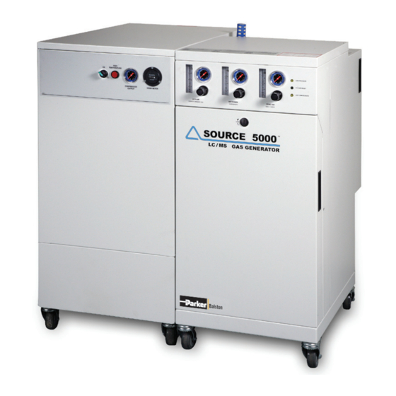
Tri-Gas Generator Series General Description The Source LC/MS Tri-Gas 5000 Generator Series are available in three models (figures 1a,b,c): (1) LCMS-5000, Tri-Gas Generator, Compressor and Receiver Tank (visually integrated model) (2) LCMS-5001T, Tri-Gas Generator and Receiver Tank (3) LCMS-5001NT, Tri-Gas Generator The visually integrated system is engineered to produce pure nitrogen for curtain gas;... - Page 5 Installation, Operation and Maintenance Manual Bulletin TI-LCMS-5000V Tri-Gas Generator Series Figure 3: Tri-Gas Generator Flow for LCMS-5000 and LCMS-5001T Figure 4: Tri-Gas Generator Flow for LCMS-5001NT Prefilters Two stages of high efficiency coalescing prefiltration are incorporated into the design of the Source 5000 to remove water and particulate contamination to 0.01 micron.
-
Page 6: Installation
The LCMS-5000 Generator has casters and is packed in a wooden shipping container. The Installation Kit, consisting of plastic tubing, silencers, and a plastic disposal container, is packed inside the container. - Page 7 To provide adequate ventilation and servicing for the generator, a minimum clear- ance distance of 30 inches in front and in the rear is required. For the LCMS-5000 Installation, the Tri-Gas generator cabinet should be located on the right side of the compressor cabinet (see figure 7).
- Page 8 (P/N 76080) should be installed directly upstream from the generator (see Recommended Acces- sories on page 10). The LCMS-5000 creates minimal noise during operation. The noise generated is about 49 dB at one meter. Periodically there is an air discharge noise from the drain port eliminating accumu- lated fluids in the prefilters and receiver tank.
- Page 9 120VAC operation only. Piping There are six plastic tubing connections for the LCMS-5000 Model: (1) inter-connection; (2) drain connections; and (3) outlet gas connections. The inter-connection tube requires a length of PFA plastic 3/8” tubing connecting the outlet of the compressor cabinet to the inlet of the Tri-Gas gen- erator (figure 11).
-
Page 10: Recommended Accessories
Installation, Operation and Maintenance Manual Bulletin TI-LCMS-5000V Tri-Gas Generator Series Drains The compressor drain tube is a black nylon 1/4” tubing connecting the drain outlet to the provided disposal container (see figure 12). A blue silencer is provided to reduce the discharge noise. The Tri-Gas generator drain tube is also a black nylon 1/4”... -
Page 11: Operation
The yellow “Low Pressure” LED temporarily illuminates until the system pressure reaches 105 psig (7.2 barg) for model LCMS-5000 (for models LCMS-5001T and LCMS-5001NT, 85 psig or 5.8 barg). The yellow “Low Temperature” LED illuminates up to 10 minutes, then goes out. The green “System Ready”... - Page 12 Installation, Operation and Maintenance Manual Bulletin TI-LCMS-5000V Tri-Gas Generator Series Each cabinet has its own automatic water drain system. The compressor drain operates every 40 min- utes, opens for 2 seconds. In the Tri-gas generator, the two filter bowls drain every 5 minutes and the receiver tank drains every 30 minutes for less than one second.
-
Page 13: Power Interruption
Tri-Gas Generator Series Pressure Interruption For Model LCMS-5000, If the compressed air pressure decreases less than 105 psig (7.2 barg), the yellow “Low Pressure” LED will illuminate and an audible alarm will sound (beeping every 2 seconds). Once pressure is restored, the LED will go out and the audible alarm will stop. For Models LCMS-5001T and LCMS-5001NT the set-point is 85 psig (5.8 barg). -
Page 14: Maintenance
15,000 3 years (P/N 76811) Frequency hours for Model LCMS-5000 is recorded by an hour meter. The hour meter is located on the compressor control panel. Note: The meter indicates 00000.0 hours. The hour meter does not reset. Frequency for Models LCMS-5001T and LCMS-5001NT is by calendar time (No Hour Meter). - Page 15 15,000 3 years (P/N BN75117) Frequency hours for Model LCMS-5000 is recorded by an hour meter. The hour meter is located on the compressor control panel. Note: The meter indicates 00000.0 hours. The hour meter does not reset. Frequency for Models LCMS-5001T and LCMS-5001NT is by calendar time (No Hour Meter).
-
Page 16: Intake Filter
Installation, Operation and Maintenance Manual Bulletin TI-LCMS-5000V Tri-Gas Generator Series Cleaning If necessary, wipe the compressor or generator with a clean, dry cloth on an as-needed basis. Do not use water, aerosols or other cleaning agents on the units. Use of any liquid detergent to clean the units could pose an electrical hazard. - Page 17 Installation, Operation and Maintenance Manual Bulletin TI-LCMS-5000V Tri-Gas Generator Series Table 1 - Grease Delivery SLAE03E Bearing 1st Pump 2nd Pump Orbit Scroll Bearing 5 times 4 times Pin Crank Bearing 4 times 4 times (Orbit Scroll side) Figure 27 Grease and Orbit Scroll Bearing Grease Pin Crank 1 Remove top and side service panels (see figure 8).
- Page 18 Installation, Operation and Maintenance Manual Bulletin TI-LCMS-5000V Tri-Gas Generator Series Grease Fittings for pin crank bearings Figure 28 Grease Fittings for Pin Crank Bearings Note: The grease fitting located in the center of the pin crank bearing feeds only the orbit scroll side bearing.
- Page 19 Installation, Operation and Maintenance Manual Bulletin TI-LCMS-5000V Tri-Gas Generator Series Caution! Do not attempt to remove the orbit scroll from the housing. 9 After installing half of the low pressure seal, carefully remove the seal from the channel to make sure the seal is properly locking onto the channel indentations located just past the high pressure seal.
- Page 20 Installation, Operation and Maintenance Manual Bulletin TI-LCMS-5000V Tri-Gas Generator Series Schedule 2 and 3 Instructions These instructions describe the replacing of the two coalescing pre-filters, the four in-line filters, the two carbon modules, and the zero air tower module in the Tri-Gas generator. Coalescing Prefilters 1 Remove the front panel from the Tri-Gas generator by rotating the latch a quarter turn counter clockwise with a screwdriver.
- Page 21 Installation, Operation and Maintenance Manual Bulletin TI-LCMS-5000V Tri-Gas Generator Series In-Line Filters There are four in-line filters requiring replacement (for model LCMS-5001NT three in-line filters). The replacement element (050-05-BX) is the same for all in-line filters (see figure 24A). By hand (or with wide-grip pliers, if necessary), rotate the bowl counter clockwise, remove and replace the filter element with a new one, return bowl, and hand tighten (see figures 34 &...
- Page 22 Installation, Operation and Maintenance Manual Bulletin TI-LCMS-5000V Tri-Gas Generator Series 3 Remove black velcro strap from one carbon module (see figure 40). 4 Remove tubing from top of module (see figure 41). Remove tubing from bottom of module. 5 Pull out module and replace new. Insert tubing, top and bottom. 6 Perform steps 3 through 5 for the other two carbon modules.
-
Page 23: Tower Module
After the initialization period, the generator will commence operation from the warm-up stage. Note: if the “Low Temperature” indicator light continues to blink after 5 to 10 minutes, please contact the factory at 1-800-343-4048. Send email to: balstontechsupport@parker.com. 1-800-343-4048 www.labgasgenerators.com... -
Page 24: Fuse Replacement
Installation, Operation and Maintenance Manual Bulletin TI-LCMS-5000V Tri-Gas Generator Series Figure 45 Inlet / Outlet Figure 46 Dryer Membrane Figure 47 Nut Figure 48 Disconnect Electrical Figure 49 Disconnect Electrical at PCB Fuse Replacement The Tri-Gas Generator fuses are located in the power receptacle on the top, rear side of the gen- erator. -
Page 25: System Specifications
31”L x 20”W x 43”H (80cm x 51cm x 109cm) Dimensions LCMS-5001NT ------- 21”L x 23”W x 41”H (53cm x 58cm x 104cm) Product Weight LCMS-5000 611 lbs (277 kgs) ------- Product Weight LCMS-5001T ------- 271 lbs (123 kgs) Product Weight LCMS-5001NT... - Page 26 Installation, Operation and Maintenance Manual Bulletin TI-LCMS-5000V Tri-Gas Generator Series Cautions The flow meter reading is dimensionless. Read flowmeter at the middle of the ball. The ac- tual flow at various operating pressures is converted into SLPM (standard liters per minute) in the flow chart label on the unit, or in the flow charts section of this manual.
-
Page 27: Replacement Parts
E-Style (Pump No. SLAE03E), or E-Style Two Belt (Pump No. SLAE03EB). Pump 14. Serial Number revision letters described on Page 15. number is located on the product label on the right side of the compressor. 15. Kit 9 includes (2) Belts: For Serial Numbers LCMS-5000-1012 to -1015. Accessory Parts Part Number... - Page 28 Installation, Operation and Maintenance Manual Bulletin TI-LCMS-5000V Tri-Gas Generator Series Nominal conditions for the charts are Temperature 68°F (20°C) and Ambient Pressure 14.7 psi [1013 mbar(a)]. The maximum pressure specification for the DRY AIR is 60 psig. Flow meter accuracy +/- 0.2 (Dewpoint -40°F). The number in the charts is from the ball on the flow meter scale.
- Page 29 Installation, Operation and Maintenance Manual Bulletin TI-LCMS-5000V Tri-Gas Generator Series The maximum pressure specification for the ZERO AIR is 110 psig. Flow meter accuracy +/-0.5 (<.1 ppm Hydrocarbons measured as Methane). Flow Rate (LPM) Pressure (PSIG) 1.75 1.25 ------ ------ ------ ------ ------...
-
Page 30: Troubleshooting
If you have an integrated compressor (Model LCMS-5000), refer to the compressor troubleshooting section, otherwise check that the com- pressed air source is delivering a minimum, continuous flow of 90 SLPM (3.2 SCFM) at a pres- sure between 110 - 140 PSIG (7.6 - 9.6 barg). - Page 31 Installation, Operation and Maintenance Manual Bulletin TI-LCMS-5000V Tri-Gas Generator Series Compressor Troubleshooting Symptom Probable Cause Corrective Action Excessive noise or vibration • Drive belts are loose • Tighten belts to specification • Drive belt has separated or • Replace drive belt flat spot •...
- Page 32 2 sec- lower than 105 psig (7.2 compressor by rotating barg) spring nut clockwise until onds) LCMS-5000 only shut-off set point is mini- mum 110 psig (7.6 barg) Low pressure (light ON and • Factory compressed air •...
- Page 33 WARRANTY (NORTH AMERICA ONLY) FOR INFORMATION CONTACT YOUR LOCAL REPRESENTATIVE Parker Hannifin guarantees to the original purchaser of this product, that if the product fails or is defective within 12 months from the date of purchase, when this product is operated and main- tained according to the instructions provided with the product, then Parker guarantees, at Park- er’s option, to replace the product, repair the product, or refund the original price for the product.
- Page 34 Installation, Operation and Maintenance Manual Bulletin TI-LCMS-5000V Tri-Gas Generator Series Figure 53 Vertical Compressor Electrical Schematic 1, 60 Hz Unit 1-800-343-4048 www.labgasgenerators.com...
- Page 35 Installation, Operation and Maintenance Manual Bulletin TI-LCMS-5000V Tri-Gas Generator Series Figure 54 Vertical Compressor Electrical Schematic 2, 50 Hz Unit 1-800-343-4048 www.labgasgenerators.com...
- Page 36 Installation, Operation and Maintenance Manual Bulletin TI-LCMS-5000V Tri-Gas Generator Series Figure 55 Horizontal Compressor Electrical Schematic 3, 50 and 60 Hz Units © 2009, 2015 Parker Hannifin Corporation Printed in U.S.A. Bulletin TI-LCMS-5000V Parker Hannifin Corporation Parker Hannifin Manufacturing Limited Industrial Gas Filtration and Gas Separation &...
Need help?
Do you have a question about the LCMS-5000 and is the answer not in the manual?
Questions and answers