Table of Contents
Advertisement
Quick Links
GVI Product Manual: Frames C, D & E
Product Manual GVI
GVI: Global Vehicle Inverter Frame C, D and E
192-300300
192-300300N1 GVI
Product Manual
September 2019
We reserve the right to make technical changes.
25.09.19 06:47
192-300300N1 GVI Frames C, D & E 2019-9
The data correspond to the current status at the time of printing.
Advertisement
Table of Contents

Related Manuals for Parker GVI Series


Summary of Contents for Parker GVI Series
- Page 1 GVI Product Manual: Frames C, D & E Product Manual GVI GVI: Global Vehicle Inverter Frame C, D and E 192-300300 192-300300N1 GVI Product Manual September 2019 We reserve the right to make technical changes. 25.09.19 06:47 192-300300N1 GVI Frames C, D & E 2019-9 The data correspond to the current status at the time of printing.
- Page 2 + 49 (0781) 509-98176 Internet: www.parker.com/eme http://www.parker.com/eme Email address: sales.automation@parker.com mailto:EM-Motion@parker.com Parker Hannifin GmbH - registered office: Bielefeld HRB 35489 Management Board: Ellen Raahede Secher, Dr.-Ing. Hans-Jürgen Haas, Kees Veraart - Chairman of the board: Hansgeorg Greuner Non-warranty clause We checked the contents of this publication for compliance with the associated hardware and software.
-
Page 3: Table Of Contents
Parker EME About this document Content 1. Introduction ..................... 7 About this document ................7 1.1.1. Definitions ......................7 1.1.2. Terms and abbreviations .................. 7 1.1.3. This revision ....................... 7 1.1.4. Scope ........................7 1.1.4.1 Document structure ................. 7 1.1.5. - Page 4 Introduction GVI Product Manual: Frames C, D & E 7.12 Emergency stop switch ................. 21 7.13 Motor feedback sensor ................22 7.13.1. General ......................22 7.13.2. Sinusoidal Motor Speed Sensor Input ............22 7.14 Motor temperature sensor..............24 7.15 Double-mounting of GVI ................ 24 7.16 I/O interface ....................
- Page 5 Parker EME About this document 8.10.2. Protection ......................37 8.10.3. Circuit ........................ 37 8.11 Sensor Supply Output ................38 8.11.1. Function ......................38 8.11.2. Protection ......................38 8.11.3. Circuit ........................ 38 8.12 Sensor Supply GND ................38 8.12.1. Function ......................38 8.12.2.
- Page 6 Introduction GVI Product Manual: Frames C, D & E 13. Product Specifications................54 13.1 General....................54 13.2 Current and power output ratings ............54 13.3 DC supply voltage requirement ............55 13.4 I/O Interface technical data ..............55 13.4.1. Key input......................55 13.4.2.
-
Page 7: Introduction
1.1.3. This revision This revision replaces all previous revisions of this document. Parker has made every effort to ensure that this document is complete and accurate at the time of printing. In accordance with our policy of continuous product improvement, all data in this document is subject to change or correction without prior notice. -
Page 8: Personal Safety
Personal safety Parker provides this and other manuals to assist manufacturers in using the GVI in a proper, efficient and safe manner. Manufacturers must ensure that all persons responsible for the design and use of equipment employing the GVI have the proper professional skills and knowledge about the equipment. -
Page 9: Original Equipment Manufacturer Responsibility
Technical support Parker support original equipment manufacturers (OEM’s) with additional information on any topic covered in this document, or for additional information about other Parker products. End customers and third parties are requested to turn to the OEM for support. -
Page 10: Warranty
Failure analysis and testing of the GVI is available for the OEM at Parker. Parker does not provide any warranty or service to the GVI end users. End users are asked to turn to the original equipment manufacturer for warranty issues, service and spare part needs. -
Page 11: Product Version
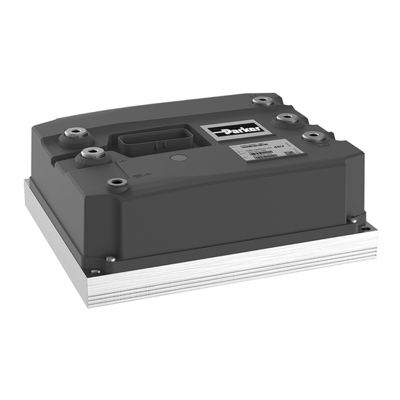
Parker EME Product version Product version The motor controller product range consists of three single drives: frames C, D and E, each with its own size and current and power output rating characteristics. 6.1.1. GVI drives Figure 2 GVI Frame C... -
Page 12: Components On The Gvi
Product overview GVI Product Manual: Frames C, D & E Components on the GVI Name Name B+ connection B- connection I/O connector (see chapter 8 I/O interface U1, V1 and W1 connections description) On board fuse (optional) , see section 7.7 Heat sink (see chapter 6.6 Cooling method) Figure 5 Components on the GVI Terminal posts... -
Page 13: Product Identification Label
Parker EME Product identification label Product identification label A label containing pertinent product identification information is attached to the motor controller cover. The product label fields relevant to product identification are described in Figure 7 and Table 2. Figure 7 Example of product identification label... -
Page 14: Led Status Indicator
Product overview GVI Product Manual: Frames C, D & E Description GVI product code / order code Hardware identification number as shipped Table 2 Description of product identification label LED status indicator The LED status indicator (see chapter 11.1), provides useful diagnostic information when troubleshooting vehicle problems (see chapter 11). -
Page 15: Integration Guidelines
Parker EME Introduction Integration guidelines Introduction This chapter describes guidelines for integration of the motor controller. Integration is the installation of the converter into a vehicle. The information is general in nature. General instructions for mounting of the converter in a vehicle are found in chapter 10. -
Page 16: Gvi With Cold Plate Heat Sink
Integration guidelines GVI Product Manual: Frames C, D & E 7.3.1. GVI with cold plate heat sink The motor controller with a cold plate heat sink is cooled through surface contact with the vehicle body. Specifications for surface roughness and surface flatness where motor controller is mounted to the vehicle body must be observed (see chapter 13.5.3. -
Page 17: Selecting Gvi Mounting Fasteners
Parker EME Selecting GVI mounting fasteners Selecting GVI mounting fasteners Recommended bolts and washers for mounting of the motor controller are specified in chapter 10.5.1. Wiring and connections WARNING High voltage - risk of personnel injury and/or damage to equipment High power levels are exposed at each of the connection posts. -
Page 18: Gvi 35Pin Standalone Controller Typical Wiring
Integration guidelines GVI Product Manual: Frames C, D & E 7.6.2. GVI 35pin Standalone controller typical wiring Figure 10 shows an example wiring diagram for a motor controller that is used as a standalone controller, with multiple I/O directly interfacing vehicle logic. The GVI 35pin version does not have multiple CAN pins, so if the motor controller is placed in the middle of a CAN bus, care should be taken to minimize length of the stub lines. -
Page 19: Sizing And Selection Of On-Board Fuse
Parker EME Sizing and selection of on-board fuse Sizing and selection of on-board fuse NOTE An on board fuse is not supplied with the Motor Controller. This component must be sourced separately. An on-board fuse (F1 in Figure 10) installed between the B+ and + terminals on each motor controller protects the motor controller and power distribution circuit in the event of a short circuit fault in the power conversion section. -
Page 20: Selecting Rectangular Washer For Fuse Mounting
Integration guidelines GVI Product Manual: Frames C, D & E 7.7.1. Selecting rectangular washer for fuse mounting The following issues shall be taken into consideration when selecting rectangular washers for mounting of an in-board fuse. Name Name On-board fuse Washer (terminal +) Washer (terminal +) Washer (terminal B+) Figure 12 On-board fuse washers... -
Page 21: Sizing Of Fuse F3
Parker EME Sizing of fuse F3 Sizing of fuse F3 The fuse F3 (Figure 10) is part of the HIGH_SIDE_IN/PRE_CHARGE protection (see chapter 8.9.1). Recommended fuse: 6-10 A time-lag fuse (size depending on the load in the circuit). 7.10 Main contactor The main contactor in a vehicle functions both as a power distribution component and as a key component in the motor controller protective interlock circuit. -
Page 22: Motor Feedback Sensor
Integration guidelines GVI Product Manual: Frames C, D & E 7.13 Motor feedback sensor 7.13.1. General To minimize the possibility of electrical noise coupling into motor feedback sensor wires, avoid routing cables next to conductors carrying high currents or high current pulses. Noise immunity may also be improved by using twisted conductor cable for the motor feedback sensor cables from motor to the motor controller. - Page 23 Parker EME Motor feedback sensor Figure 13. Sinusoidal analog sensor signal The sinusoidal analog sensor signals are connected to the Encoder ENC_1A & ENC_1B inputs (chapter 8.7) and the sensor is supplied using sensor supply (see chapters 8.11 and 8.12).
-
Page 24: Motor Temperature Sensor
Integration guidelines GVI Product Manual: Frames C, D & E 7.14 Motor temperature sensor A temperature sensor with a positive temperature coefficient embedded in the motor winding provides a means for the motor controller to monitor motor temperature. Motor temperature is used in the vector control algorithms and can also be used to protect the motor from overheating. -
Page 25: Incorporation Of Gvi In The Vehicle Safety System
Table 6 contains both MTTF and MTTFd values for different functions in the GVI. The typical values of MTTFd in annex C of ISO 13849-1 are used for calculation of the MTTFd for Parker’s equipment. -
Page 26: Travel And Brake Control
Integration guidelines GVI Product Manual: Frames C, D & E Travel and brake control 7.18.2.2 Performance according to EN 1175-1:1998 + A1:2010 chapter 5.9.4 Pulse control travel systems and 5.9.5 Prevention of travel (i.e. according to ISO 13849-1 Category 2, Performance level c). Figure 15 Travel and brake control 192-300300N1 GVI Frames C, D &... -
Page 27: Mttf And Mttfd Values For Different Functions
Parker EME Incorporation of GVI in the vehicle safety system MTTF and MTTFd values for different functions 7.18.2.3 The external interfaces are shown schematically in Figure 15. Table 6 contains calculated MTTFd for different functions in the motor controller for Category 2 architecture, see ISO 13849-1 chapter 6.2.5. -
Page 28: Default Parameters, Eeprom Considerations
Integration guidelines GVI Product Manual: Frames C, D & E 7.18.3. Default parameters, EEPROM considerations The EEPROM memory needs special considerations regarding safety. Most failures in the EEPROM will cause the data contained in it to be corrupt. At startup a checksum is calculated for the parameters in each EEPROM segment. -
Page 29: I/O Interface Description
Parker EME Mating connector specification I/O interface description Refer also to chapter 13.4. Mating connector specification Refer to TE Connectivity Product Specification 108-1329 and Application Specification 114-16016 for assembly instructions of the harness side (plug) connector: http://www.te.com 8.1.1. Part numbers •... -
Page 30: Key_Input
I/O interface description GVI Product Manual: Frames C, D & E Key_Input 8.3.1. Function The KEY_INPUT supplies battery voltage to the motor controller for its logic circuitry. The vehicle start Key Switch often controls power to the KEY_INPUT, as shown in Figure 10. The KEY_INPUT voltage is monitored. -
Page 31: Circuit
Parker EME HW ID1 and ID2 inputs 8.4.3. Circuit Figure 17. Schematic of the Digital input circuit HW ID1 and ID2 inputs 8.5.1. Function HW ID CANopen ID HW ID2 HW ID1 SW defined 1 (open) 1 (open) SW defined... -
Page 32: Circuit
I/O interface description GVI Product Manual: Frames C, D & E 8.5.3. Circuit Figure 18. Schematic of the HW ID input circuit Analog Inputs 8.6.1. Functions The analog inputs are for application use, such as speed or brake potentiometers. Analog inputs are connected to an Analog to Digital Converter (ADC). -
Page 33: Encoder Input
Parker EME Encoder input Encoder input 8.7.1. Function The Encoder inputs are multi-function inputs that can be used in different modes: • Active low digital input (with internal pull-up activated) Active high digital input • Analog input (default) • The encoder inputs can be used as general purpose I/O pins, but are primarily designed to interface motor feedback sensors. -
Page 34: Open Drain Output
I/O interface description GVI Product Manual: Frames C, D & E Open Drain Output 8.8.1. Function Open Drain outputs can be used for operating services such as the main contactor, relay, hydraulic valves, parking brake, etc. The Open Drain outputs may work in different modes depending on the expected behavior of the connected load. -
Page 35: Protection
Parker EME Open Drain Output 8.8.2. Protection The Open Drain outputs are protected against inductive discharge with internal freewheeling diodes to HIGH_SIDE_OUT/IN, internal short circuit detection and a capacitor to B- for ESD protection. The Open Drain outputs are not protected against reverse polarity of the battery. A way to avoid this failure mode is to activate the contactor only after the voltage over the DC-bus capacitors has reached the accepted pre charge level (see picture in chapter 8.9.1). -
Page 36: High Side In And Out
I/O interface description GVI Product Manual: Frames C, D & E High Side IN and Out 8.9.1. Function CAUTION High current – risk of damage to equipment Keep Cable length from B+ to HIGH_SIDE_IN as short as possible. High current on Open drain outputs with PWM can cause ripple voltage on the High side in and out. -
Page 37: Circuit
Parker EME Motor temperature measurement input 8.9.3. Circuit Figure 23 Schematic of the High side Switch 8.10 Motor temperature measurement input 8.10.1. Function Motor temperature sensor input for measurement of the motor winding temperature. The input is optimized for temperature sensors KTY84 with 1 000 Ω @ 100 °C, see chapter 7.14. -
Page 38: Sensor Supply Output
I/O interface description GVI Product Manual: Frames C, D & E 8.11 Sensor Supply Output 8.11.1. Function Supply for external motor speed sensors and for analog inputs. The sensor supply output current is monitored in order to detect if a load is connected. SENSOR_SUPPLY_GND pin shall be used for ground reference. -
Page 39: Protection
Parker EME 8.12.2. Protection SENSOR_SUPPLY_GND is B+ protected with a MOSFET switch, which also used for Sleep mode. When short circuit current is detected, the MOSFET switch is turned off. 8.12.3. Circuit CAUTION SENSOR_SUPPLY_GND must NOT be connected to B- externally - severe noise problems can be the result. -
Page 40: Can_120R
I/O interface description GVI Product Manual: Frames C, D & E Isolated CAN bus interface with Opto-couplers and internal +5 V supply from isolated DC/DC. Communication circuits with common-mode filter (choke and capacitor). Physical Interface according to ISO 11898-2. The CAN driver gives maximum amplitude on the CAN_High to CAN_Low signal. Ground reference for CAN, CAN_GND, must be routed together with CAN_High and CAN_Low in the CAN- bus to avoid communication problems. -
Page 41: Monitoring
Parker EME General Monitoring General In this chapter some standard monitoring features of the motor controller are described. The behavior of some monitoring features may be modified to fit a specific application. This manual describes the features and settings as they are normally implemented. Refer to the OEM vehicle manual for information specific to a certain application. -
Page 42: Installation And Maintenance Instructions
Installation and maintenance instructions GVI Product Manual: Frames C, D & E 10. Installation and maintenance instructions 10.1 Introduction This chapter contains general instructions for installation and maintenance of the motor controller. Fasteners and tightening torques for mounting of the motor controller must be specified in accordance with Chapter 7. Fasteners for connection of the terminal posts on the motor controller must be specified according to chapter 10.6. -
Page 43: Periodic Inspection & Preventive Maintenance
Periodic inspection & preventive maintenance The recommended periodic preventive inspection and maintenance for the motor controller and associated components are minimal. Parker recommends that the below items are done regularly. Refer also to chapter WARNING High voltage - risk of electric chock Disconnect the battery power supply before starting any work on the vehicle. -
Page 44: Replacement Of On-Board Fuse
Installation and maintenance instructions GVI Product Manual: Frames C, D & E 10.3 Replacement of on-board fuse WARNING High voltage - risk of electric chock Disconnect the battery power supply before starting any work on the vehicle. WARNING High voltage - risk of personnel injury and/or damage to equipment To prevent personnel injury and protect the AC Drive from possible damage due to voltage transients, the AC Drive’s internal filter capacitors shall be discharged as described in the instruction below. -
Page 45: Gvi Installation
Parker EME GVI installation 1. Disconnect the battery power supply. 2. Wait 5 minutes for internal filter capacitors to self-discharge, or apply a 100Ω (10W) resistance between + and B- terminals for 15 seconds to discharge the filter capacitors. Check that the voltage between + and B- is below 10Vdc. -
Page 46: Assembly Material For Gvi Mounting
Installation and maintenance instructions GVI Product Manual: Frames C, D & E 1. Verify that the item number stated on the motor controller label is correct for the application. 2. For flat heat sink version, apply thermal grease evenly over the heat sink surface. 3. -
Page 47: Connecting Terminal Posts
Parker EME Connecting terminal posts 10.6 Connecting terminal posts WARNING High current - risk of personnel injury and/or damage to equipment To avoid burning or overheating of the high-current terminals, ensure that the correct torque is applied to screws or nuts at production, and that proper screw length is used. -
Page 48: Terminals With Threads
Installation and maintenance instructions GVI Product Manual: Frames C, D & E 10.6.1. Terminals with threads Figure 31 shows the assembly order for the terminal connection fasteners. NOTE Mount the optional on-board fuse according to chapter 10.6.2. Name GVI Frame C GVI Frame D GVI Frame E Screw for terminal B+ (for... -
Page 49: Placement Of Rectangular Washers For On-Board Fuse
Parker EME Start-up and commissioning 10.6.2. Placement of rectangular washers for on-board fuse The optional on-board fuse is described in chapter 7.7. This chapter describes how to place rectangular washers (if used) for mounting of the on-board fuse on the terminal posts of the motor controller. -
Page 50: Verifying Motor Controller Readiness For Operation
Troubleshooting GVI Product Manual: Frames C, D & E 3. Verify that all power and signal wiring to the motor controller is correctly connected. Refer to chapter 10.6 for power connections. 4. Verify that connections to battery and motor terminals are tightened with appropriate torque (chapter 10.6). -
Page 51: General Considerations For System Design
Parker EME I/O and signal cables 12. General considerations for system design In the following section some common causes for issues in a system are listed, together with general information about how to avoid them through proper system design. 12.1 I/O and signal cables •... -
Page 52: Electrostatic Discharge
General considerations for system design GVI Product Manual: Frames C, D & E Motor and battery cables must be thermally dimensioned to match the power of the • motor controller and the motor. The European standard EN1175-1 (A 3.7) requires that the battery connector parts shall withstand 90 ºC. -
Page 53: Motor
Parker EME Motor GVI model DC bus capacitance [µF] GVI-C024-0350 24 000 GVI-C048-0280 10 880 GVI-C024-0550 GVI-D048-0450 15 640 GVI-D048-0550 17 680 GVI-D080-0230 4 590 GVI-D080-0350 6 210 GVI-D080-0400 7 020 GVI-E048-0700 21 760 GVI-E080-0500 8 640 GVI-E080-0700 12 420 Table 14 DC bus capacitance values 12.5... -
Page 54: Product Specifications
Product Specifications GVI Product Manual: Frames C, D & E 13. Product Specifications 13.1 General Description Value Supported motor types Permanent Magnet Synchronous AC motors Switching frequency 4, 8, 12, 16 kHz Operating stator current frequency 0-599 Hz Control modes Speed (rpm), Torque (Nm), Current (ARMS) or Voltage (VDC) Communication... -
Page 55: Dc Supply Voltage Requirement
Parker EME DC supply voltage requirement 13.3 DC supply voltage requirement GVI Model Nominal DC Operating Instantaneous Instantaneous supply voltage range minimum maximum [VDC] [VDC] (< 100 ms) (< 10 s) [VDC] [VDC] GVI 24 V** 16 – 32 GVI 48 V** 33 –... -
Page 56: Encoder Input
Product Specifications GVI Product Manual: Frames C, D & E 13.4.4. Encoder input Refer to Figure 20. Description Value Function Threshold level for Low < 2 V Analog to digital converter connection 12 bit ADC, input range 0-5 V Circuit Input impedance (pull-down) 44 k Ω... -
Page 57: Motor Temperature Measurement Input
Parker EME I/O Interface technical data 13.4.7. Motor temperature measurement input Refer to Figure 24. Description Value Circuit Internal voltage reference +3.0 V Input impedance 1.65 kΩ Difference voltage measurement gain Input capacitance 10nF 13.4.8. Sensor supply Refer to Figure 25. -
Page 58: Can
Product Specifications GVI Product Manual: Frames C, D & E 13.4.9. CAN Refer to Figure 27. Description Value Function Internal supply +5 V Data rate 125, 250 or 500 kbit/s CAN driver supply +5 V Circuit Capacitor (B-) for ESD protection 1 nF Termination resistor 120 Ω... -
Page 59: Gvi Frame D
Parker EME Physical characteristics GVI Frame D 13.5.2.2 13.5.2.3 GVI Frame E 192-300300N1 GVI Frames C, D & E 2019-9... -
Page 60: Surface Requirement
Product Specifications GVI Product Manual: Frames C, D & E Heat sink type (GVI H x W x L size in parenthesis) [mm] GVI Frame C: 12.5 x 200 x 150 GVI Frame D: 23 x 200 x 150 GVI Frame E: 23 x 200 x 235 Figure 34 Width (W) and length (L) of heat sinks 13.5.3. -
Page 61: Mechanical Tests
Parker EME Environmental testing & standards appliance 13.6.4. Mechanical tests Subject Standard Random vibration accelerated life EN 60068-2-64 test Fh Frequency Acceleration PSD [Hz] [g2/Hz] 0.02 0.025 0.05 0.05 0.04 0.03 0.075 0.02 0.02 Total g RMS Duration 50 h in each direction... - Page 62 Product Specifications GVI Product Manual: Frames C, D & E 192-300300N1 GVI Frames C, D & E 2019-9...
Need help?
Do you have a question about the GVI Series and is the answer not in the manual?
Questions and answers