Advertisement
Quick Links
Light Management
Universal dimming station 4-gang
Universal dimming station 4-gang
Art.-No.: UDS 4 REG HE
Operating instructions
1 Safety instructions
Electrical equipment may only be installed and fitted by electrically skilled persons.
Failure to observe the instructions may cause damage to the device and result in fire and
other hazards.
Danger of electric shock. Always disconnect before carrying out work on the devise or
load. At the same time, take into account all circuit breakers that supply dangerous
voltage to the device or load.
Danger of electric shock. Device is not suitable for disconnection from supply voltage.
The load is not electrically isolated from the mains even when the device is switched off.
Do not connect any electronic lamps, e.g. switchable or dimmable compact fluorescent
lamps or LED lamps. Device can be damaged.
Fire hazard. For operation with inductive transformers, each transformer must be fused
on the primary side in accordance with the manufacturer's instructions. Only safety
transformers according to EN 61558-2-6 may be used.
These instructions are an integral part of the product, and must remain with the end
customer.
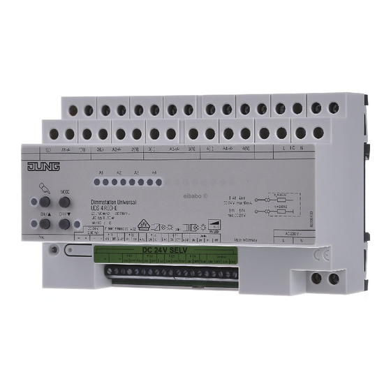
2 Device components
(1) Load outputs A1...A4
(2) Keypad for local control
(3) Button Prog, LED Prog
(4) Status LEDs for load outputs A1...A4
(5) Connection of control sections or control voltage
(6) Activation outputs A1'...A4' / Switching outputs E1 ON/OFF...E4 ON/OFF
(7) Connection Central ON/OFF
(8) Connection of hotel card switch
(9) Connection for mains supply
82577203
J:0082577203
Figure 1: Device components
1/17
31.05.2011
Advertisement

Related Manuals for Jung UDS 4 REG HE


Summary of Contents for Jung UDS 4 REG HE
- Page 1 Light Management Universal dimming station 4-gang Universal dimming station 4-gang Art.-No.: UDS 4 REG HE Operating instructions 1 Safety instructions Electrical equipment may only be installed and fitted by electrically skilled persons. Failure to observe the instructions may cause damage to the device and result in fire and other hazards.
- Page 2 Light Management Universal dimming station 4-gang (10) DIN rail Meaning of the LED in normal operation Status LED (4) red and green light up. Initialisation of load output running Status LED (4) green is illuminated. Load output switched on Status LED (4) green off Load output switched off Status LED (4) red flashes Control of load output via control section or...
-
Page 3: Operation
Light Management Universal dimming station 4-gang i Brief flickering upon load detection of ohmic loads. No operation is possible during load detection. Behaviour on failure and return of the mains power supply If only the main power supply fails, then the status of the load output remain intact at first. The dimmer station initialises when the mains power supply returns. - Page 4 Light Management Universal dimming station 4-gang i If a hotel card switch is connected, the dimmer station can only be operated when the hotel card is inserted. Switch-on local control Press the c (11) button briefly. Red status LED A1 (4) lights up, LED c (12) lights up. The device is in local control.
- Page 5 Light Management Universal dimming station 4-gang Switching the load outputs centrally All the load outputs to whom the central function has been assigned can be switched together. As long as the Mode push-button is pressed, the system is switched from the operation of a load output to central operation.
- Page 6 Light Management Universal dimming station 4-gang i When operating multiple dimmers or power boosters in a sub-distribution, maintain a distance of 1 module, approx. 18 mm, between the devices in order to prevent overheating. Mount device on DIN rail. Connection: for operation with independent load outputs Figure 3: Connection example: mains power supply, hotel card switch and loads Connect the mains power supply (figure 3).
- Page 7 Light Management Universal dimming station 4-gang Programming mode is switched on. In this operating mode, the push-buttons of the button panel (2) are assigned to the load outputs according to the table. Load output A1 Load output A2 MODE Load output A3 ON/n Load output A4 OFF/o...
- Page 8 Light Management Universal dimming station 4-gang Connecting loads to load outputs switched in parallel Figure 4: Connection example of load outputs switched in parallel CAUTION! Risk of destruction of load outputs switched in parallel if the device is set incorrectly. Dimmer and loads may be destroyed.
- Page 9 Light Management Universal dimming station 4-gang Connecting a control section Operation take place using the devices listed under Accessories. In case of operation with sensor modules (19) or push-button modules (19) do not connect any other control sections such as push-buttons (24 V) (18), push-button modules 24 V (18) and unlit installation buttons (20), to the dimmer station.
- Page 10 Light Management Universal dimming station 4-gang Figure 7: Wiring example for unlit installation button Operation of two dimmer stations with a sensor module or push-button module Sensor modules or push-button modules can operate two dimmer stations together. This requires connection of both dimmer stations in parallel. To do this, the sensor modules must have at least release version R2.
- Page 11 Light Management Universal dimming station 4-gang stations with a single push-button 24 V (figure 9), or to implement central control of several dimmer stations (figure 10). Connection example for one push-button 24 V to two dimmer stations. Here Kanal 1 and Kanal 2 of the push-button 24 V switches load output A1 of the right-hand dimmer station, and Kanal 3 and Kanal 4 switches load output A1 of the left-hand dimmer station.
- Page 12 Light Management Universal dimming station 4-gang 5.2 Commissioning DANGER! Electrical shock when live parts are touched. Electrical shocks can be fatal. Use only insulated tools when working on the device! Cover up live parts in the working environment. Overview of programming and setting modes Press the Mode button for approx.
- Page 13 Light Management Universal dimming station 4-gang The light of the load output A1...A4 is set to the minimum brightness. Press the Mode push-button until the red or green LED of load output A1 illuminates. To assign the central function for load output A1, press the ON/n (12) button. The green status LED (4) of load output A1 flashes.
- Page 14 Light Management Universal dimming station 4-gang Button assignments have been made on a module. Press the MODE and Prog buttons simultaneously until the c (12), ON/n (13) and OFF/ o (17) LED flash. The dimmer station and sensor modules or push-button modules are in cloning operation. A C flashes on the sensor modules, and all the red LEDs are flashing on the push-button modules.
-
Page 15: Troubleshooting
Light Management Universal dimming station 4-gang i Power specifications including transformer power dissipation. i Operate inductive transformers with at least 85% nominal load. i For ohmic-inductive mixed load, maximum 50% proportion of ohmic load. Otherwise incorrect calibration of the dimmer may result. i Only subject load outputs switched in parallel to up to 80%. - Page 16 Light Management Universal dimming station 4-gang Load output cannot be operated. Cause 1: load output is not ready for operation. Check installation. Check load. Cause 2: the load output is assigned to a Master as a Slave. Check the installation, adjust the dimmer station appropriately (see the chapter Mounting). Cause 3: overtemperature protection has tripped, the red Status LED (4) of the appropriate load output flashes.
-
Page 17: Warranty
We provide a warranty as provided for by law. Please send the unit postage-free with a description of the defect to our central customer service office: ALBRECHT JUNG GMBH & CO. KG Service Center Kupferstr. 17-19 D-44532 Lünen Service-Line: +49 (0) 23 55 .
Need help?
Do you have a question about the UDS 4 REG HE and is the answer not in the manual?
Questions and answers