Table of Contents
Advertisement
Quick Links
Advertisement
Table of Contents

Related Manuals for Datavideo ProRes HDR-80


Summary of Contents for Datavideo ProRes HDR-80
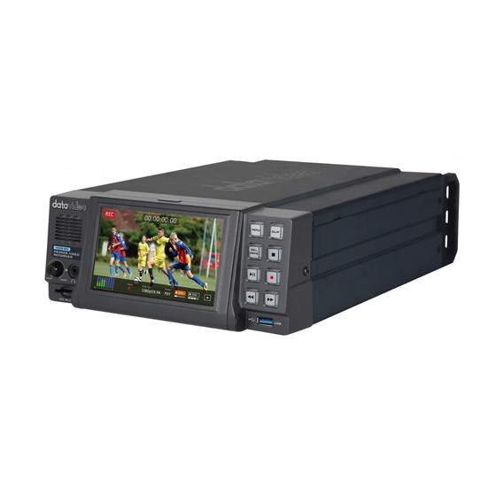
- Page 1 ProRes 4K Video Recorder Desktop HDR-80 Instruction Manual...
-
Page 2: Table Of Contents
Table of Contents FCC COMPLIANCE STATEMENT..................4 WARNINGS AND PRECAUTIONS ..................4 WARRANTY ........................5 ........................ 5 TANDARD ARRANTY ....................... 6 HREE ARRANTY DISPOSAL ......................... 6 PRODUCT OVERVIEW ....................7 1.1 F .......................... 7 EATURES 1.2 S ....................... 8 YSTEM IAGRAM CONNECTIONS AND CONTROL ................... - Page 3 Datavideo Technologies will try to give correct, complete and suitable information. However, Datavideo Technologies cannot exclude that some information in this manual, from time to time, may not be correct or may be incomplete. This manual may contain typing errors, omissions or incorrect information.
-
Page 4: Fcc Compliance Statement
AC adapter. If you are not sure of the type of power available, consult your Datavideo dealer or your local power company. 8. Do not allow anything to rest on the power cord. Do not locate this unit where the power cord will be walked on, rolled over, or otherwise stressed. -
Page 5: Warranty
Warranty Standard Warranty Datavideo equipment is guaranteed against any manufacturing defects for one year from the date of purchase. The original purchase invoice or other documentary evidence should be supplied at the time of any request for repair under warranty. -
Page 6: Three Year Warranty
PC components are covered for 1 year. The three-year warranty must be registered on Datavideo's official website or with your local Datavideo office or one of its authorized distributors within 30 days of purchase. Disposal For EU Customers only - WEEE Marking This symbol on the product or on its packaging indicates that this product must not be disposed of with your other household waste. -
Page 7: Product Overview
Product Overview The HDR-80 Desktop 4K ProRes Video Recorder is designed to record up to UHD 4K video over HDMI 12G-SDI or 4x3G-SDI. The recorder supports 12G SDI / 4K HDMI / 3 x 3G-SDI inputs as well as outputs with embedded audio. You can also embed input audio into the output video, making the HDR-80 a perfect device for live broadcast. -
Page 8: System Diagram
1.2 System Diagram... -
Page 9: Connections And Control
Connections and Control This section provides an introductory overview of the device functions on front and rear panels. 2.1 Front Panel 5” Touch Screen Menu Button This calls up the menu display on the touch screen. For more about using the menu, see MENU. CLIP Button Press the “CLIP”... - Page 10 Record Button Press to start recording. The status including the time code as well as the remaining recordable time will be displayed on the 5’’Touch Screen. For more about video recording, see Dashboard. Note: HDR-80 will not record if no video signal is present. Rew Button In playback state, press this button to Fast Rewind.
-
Page 11: Rear Panel
2.2 Rear Panel Power On / Off Button Push once to switch the HDR-80 ON/Push and hold to switch the HDR-80 OFF. DC IN Socket Connects the supplied 12V PSU to this socket. The connection can be secured by screwing the outer fastening ring of the DC In plug to the socket. - Page 12 HD/4K-HDIM Input and Output Allow input and output of HD/4K videos through the respective HDMI interfaces. HD-HDMI IN/OUT Connect external HDMI devices for playback of HD videos. Genlock IN / OUT Use Black Burst or Tri-Level Mode as video reference when synchronizing other devices to the HDR-80.
- Page 13 XLR Analog Audio OUT XLR OUT Port for audio channel 1/2 outputs and the volume is controlled by the volume knob on the front panel. Ethernet Port For remote control of the device. GPI Control The GPI socket can be used for simple external control.
-
Page 14: Ssd Slots
SSD Slots The SSD slots are located behind the 5” touch screen. To flatten the 5” touch screen, first press the latch indicated by the arrow in the diagram above then pull the screen forward, after which you should see two SSD slots as shown below. -
Page 15: Install An Ssd In A Removable Disk Enclosure
The LED indicators on the left of the front panel show disk status of SSD slots 1 and 2 respectively. Solid green light indicates normal disk function and flashing red light indicates that the HDR unit is accessing the disk. The LED will be off if no disk is inserted. - Page 16 3. Completion of disk drive enclosure assembly. 4. Push the drive enclosure into recorder as shown. Now move the locking latch from right to left side to secure the drive enclosure in place. 5. Switch ON the unit. 6. New drives will be formatted within the recorder upon first use. The status will displayed on the touch screen and will prompt the user as soon as the recorder becomes available for setup and use.
-
Page 17: Human Machine Interface
Human Machine Interface The built-in 5 inch touch screen allows you to configure the record and system settings. In addition, the user can view saved clips and live video directly on the touch screen. 5” Touch Screen First make sure the SSD is inserted; see SSD Slots for instructions if you have not already done so. -
Page 18: Dashboard
4.1 Dashboard After the system boot-up is finished, the main screen will be displayed as shown below. As soon as the record button is pushed, you will see the record function activated on the quad split screen as shown below. On the quad split screen, tap one of the screens to switch between HDMI and SDI video sources. - Page 19 5. Tap to hide timecode and menu bar. 1. Tap to go to Audio Indicator. 2. Tap to set the 3. Tap to show Disk 4. Tap to show Play Speed. Information. Sub-Menu. In the full screen mode, you can either press the Play button to play the record clip or press the Record button to start recording.
- Page 20 Record State You will see the following prompt if RECORD fails.
-
Page 21: Audio Indicator
4.1.1 Audio Indicator The respective channel audio indicators are shown below. Tap to return to Dashboard 4.1.2 Play Speed Tap to close the Play Speed dialogue box. Tap to select the play speed and close the Play Speed dialogue box. -
Page 22: Disk Information
4.1.3 Disk Information Tap SSD1 icon to display remaining recordable time and disk information. An example of the disk information is shown below. SSD 1 SSD 2 Total: 953 GB Total: 953 GB Free: 880 GB Free: 953 GB Available: 2hr4min Available: 2hr15min Note: If only SSD2 slot contains the hard disk, then the disk information will not be displayed. -
Page 23: Sub-Menu
4.1.4 Sub-Menu Tap anywhere on the screen to show time code and the sub-menu. 1. Focus Assist 5. Vectorscope 3. Waveform 8. LCD Display 7. Multiview 2. Zebra 6. Loop Play 4. Histogram 9. Tap to hide timecode and menu bar. Focus Assist 3. -
Page 24: Zebra
Zebra 3. Zebra Color 6. Tap to close 1. Zebra Forward ON/OFF 2. Zebra Backward ON/OFF 4. Zebra Threshold Minimum 5. Zebra Threshold Maximum Default forward zebra pattern: Green Default backward zebra pattern: Black Waveform 3. Tap to close 1. Waveform Display 2. -
Page 25: Vectorscope
color produced in this way has a specific brightness value based on mixes of red, green and blue throughout the image and these brightness values of all the different colors in an image are represented in a histogram which is known as the RGB histogram. Vectorscope 1. -
Page 26: Multiview
Multiview Tap the Multiview icon to switch to Multiview Display. LCD Display 1. Tap to close 2. Tap to decrease 3. Tap to increase... -
Page 27: Clip
4.2 CLIP Pressing the CLIP button should bring up the clip management screen on the 5” touch screen as shown below. Tapping OK will take you to the clip thumbnails page. Bin with Multiple Clips Tap once to play Tap to go to The bin contains more the clip next page... -
Page 28: Bin With Multiple Clips
4.2.1 Bin with Multiple Clips On the screen showing clip thumbnails, after tapping the clip thumbnail that has multiple clips, you should see the following screen. Double tap one of them to play the clip. Tap to return to clip thumbnails 4.2.2 Single Clip Deletion To delete a particular clip on the screen showing clip thumbnails, first tap one of the clip thumbnails then tap the Delete button. -
Page 29: Multiple Clip Deletion
4.2.3 Multiple Clip Deletion On the clip thumbnail screen, tap and hold until the screen below appears then select the clips that you would like to delete. You can also tap “Select ALL” button to select all of them. Select the clip Select all clips Cancel to return to Delete selected clips... -
Page 30: Input
4.3.1 Input 3. Tap to open 1. Tap to open 2. Tap to open Info page Control Setting page System Setting page 5. Tap to enter 6. Tap to enter 4. Tap to enter Input PsF Setup XLR Setup Channel Setup Input Chanel Setup Tap to select one setup. -
Page 31: Psf Setup
PsF Setup Tap to select one setup. Select None if you want to record a 1080i video source in 1080i format. PsF stands for Progressive segmented Frame, which allows you to record a 1080i60 video source in 1080p30 format. Also enable PsF if you are recording a PsF video source. 3:2 Pull Down allows you to record a 1080i59.94 video source in 1080p23.97 format. -
Page 32: Time Code
Time Code Various time code options are described as follows: Rec Run: Time code runs during video recording. Free Run: Time code runs automatically. Embedded: Video embedded time code External: Linear (or Longitudinal) Timecode (LTC) 4.3.2 Control 1. -
Page 33: System
4.3.3 System 1. Tap to enter Time Zone Setting page. 2. Tap to format the SSD. 3. Tap to enter XLR Setup page. 4. Tap to activate factory reset. Time Zone 1. Tap to move 1. Tap to move between different between different time zones. -
Page 34: Format Ssd
2. Scroll up and 1. Scroll up and down to adjust down to adjust the time. the date. 3. Tap to go back to 4. Tap to save the new the previous page settings and go back to the (Time Zone). previous page (Time Zone). - Page 35 Disk Formatting is in progress. Once the disk format is complete, you will see the prompt shown below.
-
Page 36: Xlr Setup
If the disk format fails, you will also be prompted. Tap “OK” to re-run the process. XLR Setup 1. Tap to go back to the previous page (System). -
Page 37: Reset
Reset 1. Tap to go back to 2. Tap to proceed the previous page with system reset. (System). 4.3.4 Info... -
Page 38: Firmware Update
Firmware Update Datavideo usually releases new firmware containing new features or reported bug fixes from time to time. Customers can either download the firmware as they wish or contact their local dealer or reseller for assistance. This section outlines the firmware upgrade process which should take approximately few minutes to complete. -
Page 39: Frequently Asked Questions
Frequently Asked Questions This section describes problems that you may encounter while using HDR-80. If you have any questions, please refer to related sections and follow all suggested solutions. If problem still exists, please contact your distributor or the service center. Problems Solutions The connected monitor cannot... -
Page 40: Dimensions
Dimensions HDR-80 All measurements in millimeters (mm) -
Page 41: Product Specifications
Product Specifications Model Name HDR-80 Product Name 4K ProRes Video Recorder – Desktop Video Standard UHD & HD 2160p 23.98/24/25/29.97/30/50/59.94/60 Hz 1080p 23.98/24/25/29.97/30/50/59.94/60 Hz Video Format 1080i 50/59.94/60 Hz 720p 50/59.94/60 Hz 1 x 3G/12G-SDI Supported Video Input 3 x 3G-SDI 1 x HDMI 2.0 Signal 1 x HDMI 1.4... - Page 42 RS-232/422 (D-Sub 9pin) External Control DVIP (Ethernet) GPI (φ3.5 phone jack) Power Failure Protection Chassis Desktop Dimensions (L x W x H) 313 x 220 x 97 mm Weight 2.8 kg Operating Temperature 0°C - 40°C [32°F - 104°F] Power DC 12V, 3A...
- Page 43 Notes...
-
Page 44: Service & Support
Nov-06.2020 Datavideo Technologies Co., Ltd. All rights reserved 2020 Version E1...
Need help?
Do you have a question about the ProRes HDR-80 and is the answer not in the manual?
Questions and answers