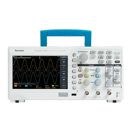
Tektronix TBS1000C Series Technical Reference
Digital storage oscilloscope
Hide thumbs
Also See for TBS1000C Series:
- User manual (218 pages) ,
- Service manual (36 pages) ,
- User manual (146 pages)

Subscribe to Our Youtube Channel
Related Manuals for Tektronix TBS1000C Series


Summary of Contents for Tektronix TBS1000C Series
- Page 1 TBS1000C Series Oscilloscopes Series Digital Storage Oscilloscope Technical Reference *P077158300* 077-1583-00...
- Page 3 TBS1000C Series Oscilloscopes Series Digital Storage Oscilloscope Technical Reference Warning The servicing instructions are for use by qualified personnel only. To avoid personal injury, do not perform any servicing unless you are qualified to do so. Refer to all safety summaries prior to performing service.
- Page 4 Tektronix. All rights reserved. Licensed software products are owned by Tektronix or its subsidiaries or suppliers, and are protected by national copyright laws and international treaty provisions. Tektronix products are covered by U.S. and foreign patents, issued and pending. Information in this publication supersedes that in all previously published material. Specifications and price change privileges reserved.
-
Page 5: Table Of Contents
Check DC gain accuracy ........................Check bandwidth ............................ Check sample rate accuracy and delay time accuracy ................Check edge trigger sensitivity ........................ Check Aux In edge trigger sensitivity ..................... Check Vertical Position Accuracy ......................Data verification ............................TBS1000C Series Specification and Performance Verification... - Page 6 Table of Contents Example off vertical position accuracy test spreadsheet Sample Filled-In Vertical Position Accuracy ....................TBS1000C Series Specification and Performance Verification...
-
Page 7: Important Safety Information
Connect and disconnect properly. Do not connect or disconnect probes or test leads while they are connected to a voltage source. Use only insulated voltage probes, test leads, and adapters supplied with the product, or indicated by Tektronix to be suitable for the product. - Page 8 Keep fingers behind the protective barrier, protective finger guard, or tactile indicator on the probes. Remove all probes, test leads and accessories that are not in use. Use only correct Measurement Category (CAT), voltage, temperature, altitude, and amperage rated probes, test leads, and adapters for any measurement. TBS1000C Series Specification and Performance Verification...
-
Page 9: Service Safety Summary
Use care when servicing with power on. Dangerous voltages or currents may exist in this product. Disconnect power, remove battery (if applicable), and disconnect test leads before removing protective panels, soldering, or replacing components. Verify safety after repair. Always recheck ground continuity and mains dielectric strength after performing a repair. TBS1000C Series Specification and Performance Verification... -
Page 10: Terms In The Manual
(This symbol may also be used to refer the user to ratings in the manual.) The following symbols may appear on the product: TBS1000C Series Specification and Performance Verification... -
Page 11: Specifications
From 2 to 512 waveforms included in average. Hi-Res Averages multiple sample of one acquisition interval into one waveform point. Roll Scrolls waveforms right to left across the screen at sweep speeds slower than or equal to 40 ms/ TBS1000C Series Specification and Performance Verification... -
Page 12: Horizontal Systems - Analog Channel
The settings are retained when the line power is turned off and on. The instrument periodically saves front panel settings after settings are changed. There is a delay of three seconds after the last change and before the storage of the settings in memory. TBS1000C Series Specification and Performance Verification... - Page 13 Analog bandwidth selections 20 MHz bandwidth limit ON/OFF Upper-Frequency limit, 20 MHz This is the upper frequency for Analog Bandwidth when the instrument has 20 MHz bandwidth bandwidth limited, typical limiting turned on. 20 MHz, ±25% TBS1000C Series Specification and Performance Verification...
- Page 14 >100:1 with 70 MHz sine wave and with equal V/ div settings on each channel. TBS1052C (50 MHz models) >100:1 with 50 MHz sine wave and with equal V/ div settings on each channel. TBS1000C Series Specification and Performance Verification...
-
Page 15: Waveform Measurements
The following limits are given for signals having an amplitude ≥ 5 divisions, a slew rate at the measurement points of ≥ 2.0 divisions/ns, and acquired ≥ 10 mV/div. TBS1000C Series Specification and Performance Verification... -
Page 16: Waveform Math
Line trigger characteristics Line Trigger mode provides a source to synchronize the trigger with the AC line input. Input Amplitude requirements: 85 V - 265 V Input Frequency requirements: 45 Hz - 440 Hz. TBS1000C Series Specification and Performance Verification... - Page 17 100 MHz 500 mV from 100 MHz 350 mV from 100 MHz to 200 MHz to 200 MHz TBS1202C TBS1202C Trigger frequency feadout typically stabilizes at 50% more signal than generates a stable visual display. TBS1000C Series Specification and Performance Verification...
- Page 18 Falling edge for positive polarity pulse. Rising edge for negative polarity pulse. Pulse width range 33 ns ≤ width ≤ 10 seconds Pulse width resolution 16.5 ns or 1 part per thousand, whichever is larger TBS1000C Series Specification and Performance Verification...
- Page 19 All pulses, even from the most stable sources, have some amount of jitter. To avoid disqualifying pulses that are intended to qualify but are not absolutely correct values, Tektronix provides an arbitrary guardband. Any measured pulse width within the guardband will qualify. If you are looking for pulse width...
-
Page 20: Display Specifications
B. One, both, or neither of A or B waveform memories can be displayed. Ten user setups of the current instrument settings can be saved and restored from nonvolatile memory. Additional storage is available when an appropriate mass storage device is connected via USB. TBS1000C Series Specification and Performance Verification... -
Page 21: Power Distribution System
Width 482.6 19.0 Depth 108.0 4.25 Shipping dimensions Height 266.7 10.5 Width 476.2 18.75 Depth 228.6 Dimensions Height- Handle folded down 154.95 Height-Handle up 213.36 Width 325.12 12.8 Depth 106.68 Cooling method Convection cooled TBS1000C Series Specification and Performance Verification... -
Page 22: Environmental Performance
Up to 3,000 meters (9,842 feet) Non-operating: Up to 12,000 meters (39,370 feet). Regulatory Electromagnetic EC Council Directive 2014/30/EU Compatibility UL61010-1, UL61010-2-030, CAN/CSA-C22.2 No. 61010.1, CAN/CSA-C22.2 No. 61010-2:030 Safety Compiles with the Low Voltage Directive 2014/35/EU for Product Safety TBS1000C Series Specification and Performance Verification... -
Page 23: Performance Verification
BNC male to BNC male, ≈ 1 m (36 in) long Tektronix part number 012-0482-XX 50Ω BNC cable BNC male to BNC male, ≈ 25 cm (10 in) long Tektronix part number 012-0208-XX 50 Ω feed through termination BNC male and female connectors... -
Page 24: Test Record
Channel 1 Vertical Position Accuracy, — Minimum margin Channel 2 Vertical Position Accuracy, — Minimum margin The bandwidth test does not have a high limit. The limits vary by model. Check the procedure for the correct limits. TBS1000C Series Specification and Performance Verification... -
Page 25: Performance Verification Procedures
Set the DC voltage source output level to 0 V. Set up the oscilloscope using the following table: Push menu button Select menu option Select setting Default Setup Channel 1 Probe Acquire Average Measure Source Channel under test Measurements Mean TBS1000C Series Specification and Performance Verification... -
Page 26: Check Bandwidth
This test checks the bandwidth of all input channels. Set up the oscilloscope using the following table: Push menu button Select menu option Select setting Default Setup Channel 1 Probe Acquire Average Trig Menu Coupling Noise Reject TBS1000C Series Specification and Performance Verification... -
Page 27: Check Sample Rate Accuracy And Delay Time Accuracy
11. Repeat steps 1 through 10 for all input channels. Check sample rate accuracy and delay time accuracy This test checks the sample rate and delay time accuracy (time base). Set up the oscilloscope using the following table: TBS1000C Series Specification and Performance Verification... - Page 28 10. Check that the rising edge of the marker crosses the center horizontal graticule line within ±2 divisions of the vertical center graticule line, as shown in the following figure: NOTE. One division of displacement from graticule center corresponds to a 25 ppm time base error. 11. Disconnect the test setup. TBS1000C Series Specification and Performance Verification...
-
Page 29: Check Edge Trigger Sensitivity
Set the oscilloscope Horizontal Scale (seconds/division) to 4 ns/div. 10. Set the leveled sine wave generator output level to approximately 750 mV so that the measured amplitude is approximately 750 mV. (The measured amplitude can fluctuate around 750 mV.) TBS1000C Series Specification and Performance Verification... -
Page 30: Check Aux In Edge Trigger Sensitivity
This test checks the edge trigger sensitivity for the Aux In. Set up the oscilloscope using the following table: Push menu button Select menu option Select setting Default setup Channel 1 Probe Trig Menu Source Aux In Mode Normal Acquire Sample TBS1000C Series Specification and Performance Verification... - Page 31 10. Set the oscilloscope Horizontal Scale (seconds/division) to 2 ns/div. 11. Push the Trigger Level knob to activate the Set To 50% feature. Rotate the Trigger Level knob to adjust the trigger level as necessary and then check that triggering is stable. TBS1000C Series Specification and Performance Verification...
-
Page 32: Check Vertical Position Accuracy
The values in columns B, C, D, E, F, and G are examples of the measured or calculated values. The PDF version of the technical reference manual (which you can download from www.tektronix.com/manuals), includes an empty spreadsheet for your convenience. To access and save the test spreadsheet, see the instructions in Appendix. A: Example of a Vertical Position Accuracy test spreadsheet on page A-1. - Page 33 Repeat steps 4 through 6 for the values of -0.08 V through -1.8 V in -0.08 V steps. 10. Enter the Minimum Margin number (cell I16) for the channel tested in the test record. 11. Repeat steps 1 through 10 for all input channels. TBS1000C Series Specification and Performance Verification...
-
Page 34: Data Verification
(upper line), or below the purple line (lower line). For calculations involved in this example, refer to the data in the previous table (see step 1). Figure 1: Example of a line graph for the Vertical Position Accuracy test TBS1000C Series Specification and Performance Verification... - Page 35 This appendix contains a filled-in example of the vertical position accuracy (VPA) test spreadsheet that is used. The PDF version of this technical reference manual (Tektronix part number 077-1583-xx) includes an empty VPA test spreadsheet for your convenience. To access and save the test spreadsheet: Go to the Tektronix manuals Web site, www.tektronix.com/manuals.
- Page 36 -1.08 -1.08 0.000 -0.0208 0.0208 0.021 -1.16 -1.16 -1.16 0.000 -0.0216 0.0216 0.022 -1.24 -1.24 -1.24 0.000 -0.0224 0.0224 0.022 -1.32 -1.32 -1.32 0.000 -0.0232 0.0232 0.023 -1.40 -1.4 -1.4 0.000 -0.024 0.024 0.024 TBS1000C Series Specification and Performance Verification...
- Page 37 0.025 -1.56 -1.56 -1.56 0.000 -0.0256 0.0256 0.026 -1.64 -1.64 -1.64 0.000 -0.0264 0.0264 0.026 -1.72 -1.72 -1.72 0.000 -0.0272 0.0272 0.027 -1.80 -1.8 -1.79 -0.010 -0.028 0.028 0.018 -1.84 -1.88 -1.92 -1.96 -2.00 TBS1000C Series Specification and Performance Verification...
- Page 38 Example off vertical position accuracy test spreadsheet TBS1000C Series Specification and Performance Verification...
- Page 39 16 Sample rate and delay time accuracy test, 17 self calibration, 15 calibration, 15 Self test, 15 DC gain accuracy test, 15 Delay time accuracy test, 17 Test record, 14 Required equipment, 13 TBS1000C Series Specification and Performance Verification...
- Page 40 Index TBS1000C Series Specification and Performance Verification...
Need help?
Do you have a question about the TBS1000C Series and is the answer not in the manual?
Questions and answers