
Subscribe to Our Youtube Channel
Related Manuals for Tektronix TBS1032B


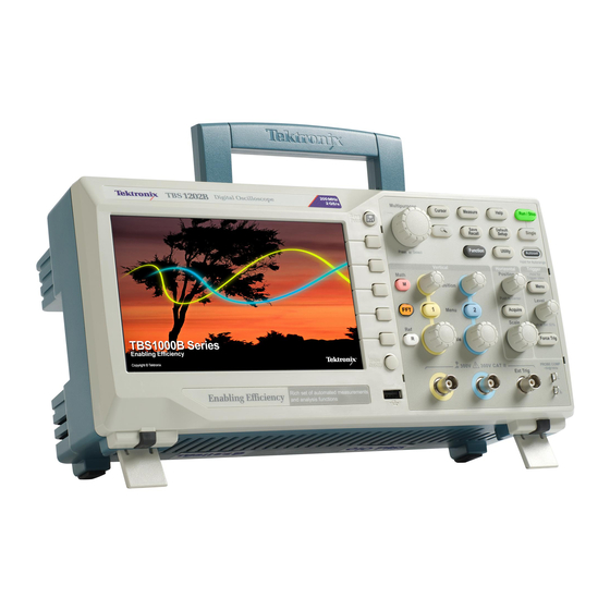
Summary of Contents for Tektronix TBS1032B
- Page 1 TBS1000B and TBS1000B-EDU Series Digital Storage Oscilloscopes User Manual *P077088602* 077-0886-02...
- Page 3 TBS1000B and TBS1000B-EDU Series Digital Storage Oscilloscopes User Manual Revision A www.tek.com 077-0886-02...
- Page 4 Tektronix. All rights reserved. Licensed software products are owned by Tektronix or its subsidiaries or suppliers, and are protected by national copyright laws and international treaty provisions. Tektronix products are covered by U.S. and foreign patents, issued and pending. Information in this publication supersedes that in all previously published material.
- Page 5 Warranty Tektronix warrants that the product will be free from defects in materials and workmanship for a period of five (5) years from the date of original purchase from an authorized Tektronix distributor. If the product proves defective during this warranty period, Tektronix, at its option, either will repair the defective product without charge for parts and labor, or will provide a replacement in exchange for the defective product.
- Page 6 Warranty Tektronix warrants that the product will be free from defects in materials and workmanship for a period of one (1) year from the date of original purchase from an authorized Tektronix distributor. If the product proves defective during this warranty period, Tektronix, at its option, either will repair the defective product without charge for parts and labor, or will provide a replacement in exchange for the defective product.
-
Page 7: Table Of Contents
Table of Contents Important safety information ......................General safety summary ....................... Service safety summary ........................Terms in the manual ........................Terms on the product ........................Symbols on the product ......................... Compliance information ........................xiii EMC compliance ......................... xiii Safety compliance ........................ - Page 8 Table of Contents Trigger controls ..........................Menu and control buttons ......................Input connectors ........................... Other front-panel items ......................... Understanding oscilloscope functions Setting up the oscilloscope ......................Using autoset ........................... Using autorange ........................Saving a setup .......................... Recalling a setup ........................Default setup ..........................
- Page 9 Table of Contents Measuring pulse width ......................Measuring rise time ......................... Analyzing signal detail ......................... Looking at a noisy signal ......................Separating the signal from noise ..................... Capturing a Single-Shot signal ..................... Optimizing the acquisition ...................... Measuring propagation delay ....................... Triggering on a specific pulse width ....................
- Page 10 Table of Contents Recall setup and recall waveform options ................Using the save function of the Front-Panel save button ............... Saves all to files ........................Saves image to file ........................USB device port ..........................Installing the PC communications software on a PC ..............
- Page 11 Table of Contents Measure ............................Key points ..........................Measurement gating ........................Menu off ............................Print-Ready screenshots ....................... Reference menu ..........................Save-Recall ........................... Save all ............................ Save image ..........................Save setup ..........................Save waveform ........................Recall setup ..........................Recall waveform ........................Key points ..........................
- Page 12 Table of Contents Horizontal system — Analog channels ..................Input/Output ports ........................Data storage ..........................Acquisition system ........................Trigger system ..........................Waveform measurements ......................Waveform math .......................... Autoset ............................Autorange ........................... Frequency counter ........................Display system ..........................Power source ..........................Physical characteristics .......................
-
Page 13: Important Safety Information
Important safety information This manual contains information and warnings that must be followed by the user for safe operation and to keep the product in a safe condition. To safely perform service on this product, see the Service safety summary that follows the General safety summary. - Page 14 Use only insulated voltage probes, test leads, and adapters supplied with the product, or indicated by Tektronix to be suitable for the product. Observe all terminal ratings. To avoid fire or shock hazard, observe all rating and markings on the product.
- Page 15 Important safety information Wear eye protection. Wear eye protection if exposure to high-intensity rays or laser radiation exists. Do not operate in wet/damp conditions. Be aware that condensation may occur if a unit is moved from a cold to a warm environment. Do not operate in an explosive atmosphere.
-
Page 16: Service Safety Summary
Important safety information Connect the probe reference lead to earth ground only. Do not connect a current probe to any wire that carries voltages or frequencies above the current probe voltage rating. Inspect the probe and accessories. Before each use, inspect probe and accessories for damage (cuts, tears, or defects in the probe body, accessories, or cable jacket). -
Page 17: Terms In The Manual
Important safety information Terms in the manual These terms may appear in this manual: WARNING. Warning statements identify conditions or practices that could result in injury or loss of life. CAUTION. Caution statements identify conditions or practices that could result in damage to this product or other property. - Page 18 Important safety information TBS1000B and TBS1000B-EDU Series Oscilloscopes User Manual...
-
Page 19: Compliance Information
Compliance information This section lists the EMC (electromagnetic compliance), safety, and environmental standards with which the instrument complies. EMC compliance EC Declaration of Meets intent of Directive 2014/30/EU for Electromagnetic Compatibility. Compliance was demonstrated to the following specifications as listed in the Conformity –... -
Page 20: Safety Compliance
Compliance information EMC compliance Meets the intent of Directive 2004/108/EC for Electromagnetic Compatibility when it is used with the product(s) stated in the specifications table. Refer to the EMC specification published for the stated products. May not meet the intent of the directive if used with other products. - Page 21 Compliance information U.S. nationally recognized ■ UL 61010-1. Safety Requirements for Electrical Equipment for Measurement, Control, and Laboratory Use – Part 1: General Requirements. testing laboratory listing ■ UL 61010-2-030. Safety Requirements for Electrical Equipment for Measurement, Control, and Laboratory Use – Part 2-030: Particular requirements for testing and measuring circuits.
- Page 22 Compliance information Pollution degree A measure of the contaminants that could occur in the environment around and within a product. Typically the internal environment inside a product is description considered to be the same as the external. Products should be used only in the environment for which they are rated.
-
Page 23: Environmental Compliance
This symbol indicates that this product complies with the applicable European Union requirements according to Directives 2012/19/EU and 2006/66/EC on waste electrical and electronic equipment (WEEE) and batteries. For information about recycling options, check the Tektronix Web site (www.tek.com/productrecycling). TBS1000B and TBS1000B-EDU Series Oscilloscopes User Manual xvii... - Page 24 Compliance information xviii TBS1000B and TBS1000B-EDU Series Oscilloscopes User Manual...
-
Page 25: Getting Started
NOTE. You can select a language to display on the screen after you power on the oscilloscope. At any time, you can access the Utility ► Language option to select a language. General features Model Channels Bandwidth Sample rate Display TBS1032B 30 MHz 500 MS/s Color TBS1052B-EDU 50 MHz 1 GS/s Color TBS1052B... -
Page 26: Installation
Getting started ■ Selectable 20 MHz bandwidth limit ■ 2,500 point record length for each channel ■ Autoset ■ Autoranging ■ Setup and waveform storage ■ USB Flash Drive port for file storage ■ PC communications through the USB Device port with OpenChoice PC Communications software ■... -
Page 27: Security Loop
Getting started Security loop Use a standard laptop computer security lock, or thread a security cable through the built-in cable channel to secure your oscilloscope to your location. Security cable channel Security lock hole Power cord Ventilation NOTE. The oscilloscope cools by convection. Keep two inches clear on the sides and top of the product to allow adequate air flow. - Page 28 Getting started PROBE COMP 5. Push the Autoset button. Within a few seconds, you should see a square wave in the display of about 5 V peak-to-peak at 1 kHz. 6. Push the channel 1 menu button on the front panel twice to remove channel 1, push the channel 2 menu button to display channel 2, and repeat steps 3 through 5.
-
Page 29: Probe Safety
Getting started Probe safety Check and observe probe ratings before using probes. A guard around the TPP0051, TPP0101, or TPP0201 probe body provides a finger barrier for protection from electric shock. Finger guard WARNING. To avoid electric shock when using the probe, keep fingers behind the guard on the probe body. -
Page 30: Probe Attenuation Setting
Getting started Overcompensated Undercompensated Compensated correctly 4. If necessary, adjust your probe. Repeat if necessary. Probe attenuation setting Probes are available with various attenuation factors which affect the vertical scale of the signal. Select the factor that matches the attenuation of your probe. For example, to match a probe set to 10X connected to CH 1, push the 1 ►... -
Page 31: Current Probe Scaling
Update your TBS1000B’s firmware to take advantage of new features and bug fixes. You can use the Internet and a USB flash drive to update your oscilloscope. If you do not have access to the Internet, contact Tektronix for information on update procedures. -
Page 32: Check The Version Of The Latest Available Firmware
Getting started Check the version of the 1. Open up a Web browser and go to www.tektronix.com/software. latest available firmware 2. Enter “TBS1000B” in the search box. 3. Scan the list of available software for the latest TBS1000B firmware. Check the version number. -
Page 33: Operating Basics
Operating basics The front panel is divided into easy-to-use functional areas. This chapter provides you with a quick overview of the controls and the information displayed on the screen. TBS1000B and TBS1000B-EDU Series Oscilloscopes User Manual... -
Page 34: Display Area
Operating basics Display area In addition to displaying waveforms, the display provides details about the waveform and the oscilloscope control settings. NOTE. For details on displaying the FFT function, Displaying the FFT spectrum on page 55 The items shown below may appear in the display. Not all of these items are visible at any given time. -
Page 35: Message Area
Operating basics Acq. Complete: The oscilloscope has completed a Single Sequence acquisition. Auto: The oscilloscope is in auto mode and is acquiring waveforms in the absence of trigger. Scan: The oscilloscope is acquiring and displaying waveform data continuously in scan mode. 4. -
Page 36: Using The Menu System
Operating basics Using the menu system When you push a front-panel button, the oscilloscope displays the corresponding menu on the right side of the screen. The menu shows the options that are available when you push the unlabeled option buttons directly to the right of the screen. -
Page 37: Horizontal Controls
Operating basics Horizontal controls Position. Adjusts the horizontal position of all channel and math waveforms. The resolution of this control varies with the time base setting. NOTE. To make a large adjustment to the horizontal position, turn the Horizontal Scale knob to a larger value, change the horizontal position, and then turn the Horizontal Scale knob back to the previous value. -
Page 38: Trigger Controls
Operating basics Trigger controls Trigger Menu. When it is pressed once, it displays the Trigger Menu. When it is kept pressed for more than 1.5 seconds, it will show the trigger view, meaning it will display the trigger waveform in place of the channel waveform. Use the trigger view to see how the trigger settings, such as coupling, affect the trigger signal. -
Page 39: Menu And Control Buttons
Operating basics Menu and control buttons Refer to the Reference chapter for detailed information on the menu and button controls. Multipurpose Knob. The function is determined by the displayed menu or selected menu option. When active, the adjacent LED lights. The next table lists the functions. -
Page 40: Input Connectors
Operating basics Acquire. Displays the Acquire Menu. Ref. Displays the Reference Menu to quickly display and hide reference waveforms stored in the oscilloscope non-volatile memory. Utility. Displays the Utility Menu. Cursor. Displays the Cursor Menu. Cursors remain visible (unless the Type option is set to Off) after you leave the Cursor Menu but are not adjustable. -
Page 41: Other Front-Panel Items
Operating basics Other front-panel items USB Flash Drive Port. Insert a USB flash drive for data storage or retrieval. For flash drives with an LED, the LED blinks when saving data to or retrieving data from the drive. Wait until the LED stops blinking before you remove the drive. - Page 42 Operating basics TBS1000B and TBS1000B-EDU Series Oscilloscopes User Manual...
-
Page 43: Understanding Oscilloscope Functions
Understanding oscilloscope functions This chapter contains general information that you need to understand before you use an oscilloscope. To use your oscilloscope effectively, you need to learn about the following functions: ■ Setting up the oscilloscope ■ Triggering ■ Acquiring signals (waveforms) ■... -
Page 44: Setting Up The Oscilloscope
Understanding oscilloscope functions Setting up the oscilloscope You should become familiar with several functions that you may use often when operating your oscilloscope: Autoset, Autorange, saving a setup, and recalling a setup. Using autoset Each time you push the Autoset button, the Autoset function obtains a stable waveform display for you. -
Page 45: Triggering
Understanding oscilloscope functions Triggering The trigger determines when the oscilloscope starts to acquire data and to display a waveform. When a trigger is set up properly, the oscilloscope converts unstable displays or blank screens into meaningful waveforms. Triggered waveform Untriggered waveforms For oscilloscope-specific descriptions, refer to the Operating Basics chapter. -
Page 46: Types
Understanding oscilloscope functions Types The oscilloscope provides three types of triggers: Edge, Video, and Pulse Width. Modes You can select the Auto or the Normal trigger mode to define how the oscilloscope acquires data when it does not detect a trigger condition. See Mode options. -
Page 47: Acquiring Signals
Understanding oscilloscope functions Acquiring signals When you acquire a signal, the oscilloscope converts it into a digital form and displays a waveform. The acquisition mode defines how the signal is digitized, and the time base setting affects the time span and level of detail in the acquisition. -
Page 48: Scaling And Positioning Waveforms
Understanding oscilloscope functions Scaling and positioning waveforms You can change the display of waveforms by adjusting the scale and position. When you change the scale, the waveform display will increase or decrease in size. When you change the position, the waveform will move up, down, right, or left. - Page 49 Understanding oscilloscope functions Actual high-frequency waveform Apparent low-frequency waveform due to aliasing Sample points The oscilloscope accurately represents signals, but is limited by the probe bandwidth, the oscilloscope bandwidth, and the sample rate. To avoid aliasing, the oscilloscope must sample the signal more than twice as fast as the highest frequency component of the signal.
-
Page 50: Taking Measurements
Understanding oscilloscope functions Taking measurements The oscilloscope displays graphs of voltage versus time and can help you to measure the displayed waveform. There are several ways to take measurements. You can use the graticule, the cursors, or an automated measurement. Graticule This method allows you to make a quick, visual estimate. -
Page 51: Automatic
Understanding oscilloscope functions Time Cursors. Time cursors appear as vertical lines on the display and measure both horizontal and vertical parameters. Times are referenced to the trigger point. For the FFT function, these cursors measure frequency. Time cursors also include a readout of the waveform amplitude at the point the waveform crosses the cursor. - Page 52 Understanding oscilloscope functions TBS1000B and TBS1000B-EDU Series Oscilloscopes User Manual...
-
Page 53: Application Examples
Application examples This section presents a series of application examples. These simplified examples highlight the features of the oscilloscope and give you ideas for using it to solve your own test problems. ■ Taking simple measurements ■ Using Autoset ■ Using the Measure Menu to take automatic measurements ■... -
Page 54: Taking Simple Measurements
Application examples Taking simple measurements You need to see a signal in a circuit, but you do not know the amplitude or frequency of the signal. You want to quickly display the signal and measure the frequency, period, and peak-to-peak amplitude. Using autoset To quickly display a signal, follow these steps: 1. -
Page 55: Taking Automatic Measurements
Application examples Taking automatic The oscilloscope can take automatic measurements of most displayed signals. measurements NOTE. If a question mark (?) appears in the Value readout, the signal is outside the measurement range. Adjust the Vertical Scale knob (volts/division) of the appropriate channel to decrease the sensitivity or change the horizontal Scale setting (seconds/division). -
Page 56: Measuring Two Signals
Application examples Measuring two signals If you are testing a piece of equipment and need to measure the gain of the audio amplifier, you will need an audio generator that can inject a test signal at the amplifier input. Connect two oscilloscope channels to the amplifier input and output as shown next. -
Page 57: Using Autorange To Examine A Series Of Test Points
Application examples 6. Push the Ch1 side menu. The pop-up menu of measurement types appears to the left. . 7. Turn the Multipurpose knob to highlight Peak-Peak. 8. Push the Multipurpose knob to select Peak-Peak. A check should appear next to the menu item and the peak-to-peak for channel 2 should appear towards the bottom of the display. -
Page 58: Taking Cursor Measurements
Application examples Taking cursor measurements You can use the cursors to quickly take time and amplitude measurements on a waveform. Measuring ring frequency To measure the ring frequency at the rising edge of a signal, follow these steps: and amplitude 1. -
Page 59: Measuring Pulse Width
Application examples 15. Push the Cursor 1 option button. 16. Turn the Multipurpose knob to place a cursor on the first peak of the ring. 17. Push the Cursor 2 option button. 18. Turn the Multipurpose knob to place Cursor 2 on the lowest part of the ring. You can see the amplitude of the ring in the Cursor Menu. -
Page 60: Measuring Rise Time
Application examples Type Time SourceCh1 Δt 500.0µs 1/Δt 2.000kHz ΔV 1.38V Cursor 1 0.00s 0.98V Cursor 2 500µs -1.00V NOTE. The Positive Width measurement is available as an automatic measurement in the Measure Menu. See Measure on page 91. Measuring rise time After measuring the pulse width, you decide that you need to check the rise time of the pulse. - Page 61 Application examples 14. Push the Cursor 1 option button. 15. Turn the Multipurpose knob to place a cursor at the point where the waveform crosses the second graticule line below center screen. This is the 10% level of the waveform. 16.
-
Page 62: Analyzing Signal Detail
Application examples Analyzing signal detail You have a noisy signal displayed on the oscilloscope and you need to know more about it. You suspect that the signal contains much more detail than you can now see in the display. Looking at a noisy signal The signal appears noisy and you suspect that noise is causing problems in your circuit. -
Page 63: Separating The Signal From Noise
Application examples Separating the signal from Now you want to analyze the signal shape and ignore the noise. To reduce random noise in the oscilloscope display, follow these steps: noise 1. Push the Acquire button to see the Acquire Menu. 2. -
Page 64: Optimizing The Acquisition
Application examples 7. Turn the front-panel Level knob to adjust the trigger level to a voltage midway between the open and closed voltages of the relay. 8. Push the Single button to start the acquisition. When the relay opens, the oscilloscope triggers and captures the event. Optimizing the acquisition The initial acquisition shows the relay contact beginning to open at the trigger point. -
Page 65: Measuring Propagation Delay
Application examples Measuring propagation delay You suspect that the memory timing in a microprocessor circuit is marginal. Set up the oscilloscope to measure the propagation delay between the chip-select signal and the data output of the memory device. Type Time Source Δt 20.00ns 1/Δt... -
Page 66: Triggering On A Specific Pulse Width
Application examples 6. Push the Multipurpose knob to select Time. 7. Push the Source side-menu button. A pop-out menu should appear showing a scroll-able list of the available sources. 8. Turn the Multipurpose knob to highlight Ch1. 9. Push the Multipurpose knob to select Ch1. 10. - Page 67 Application examples 7. Turn the Multipurpose knob to highlight Ch1 from the pop-out menu. Push the knob to select the choice 8. Turn the trigger Level knob to set the trigger level near the bottom of the signal. 9. Push When ► = (equals). 10.
-
Page 68: Triggering On A Video Signal
To avoid amplitude inaccuracy from improper loading and reflections, place a 75 ohm feedthrough terminator (Tektronix part number 011-0055-02 or equivalent) between the 75 ohm coaxial cable from the signal source and the oscilloscope BNC input. -
Page 69: Triggering On Video Fields
Application examples Triggering on video fields Automatic. To trigger on the video fields, follow these steps: 1. Push the Autoset button. When Autoset is complete, the oscilloscope displays the video signal with sync on All Fields. The oscilloscope sets the Standard option when you use the Autoset function. 2. -
Page 70: Using The Zoom Function To See Waveform Details
Application examples Incoming video signal Using the zoom function You can use the zoom function to examine a specific portion of a waveform without changing the main display. to see waveform details If you want to view the color burst in the previous waveform in more detail without changing the main display, follow these steps: 1. -
Page 71: Analyzing A Differential Communication Signal
Application examples Analyzing a differential communication signal You are having intermittent problems with a serial data communication link, and you suspect poor signal quality. Set up the oscilloscope to show you a snapshot of the serial data stream so you can verify the signal levels and transition times. Because this is a differential signal, you use the Math function of the oscilloscope to view a better representation of the waveform. -
Page 72: Viewing Impedance Changes In A Network
Application examples 5. Push the Math button to see the Math Menu. 6. Push the Operation option button and select -. 7. Push the Sources Ch1-Ch2 option button to display a new waveform that is the difference between the displayed waveforms. 8. - Page 73 Application examples To view the input and output of the circuit in an XY display, follow these steps: 1. Push the 1 (channel 1 menu) button. 2. Push Probe ► Voltage ►Attenuation ► 10X. 3. Push the 2 (channel 2 menu) button. 4.
-
Page 74: Data Logging (Non-Edu Models Only)
Application examples 11. Turn the Vertical Scale and Vertical Position knobs to optimize the display. 12. Push Persist ► Infinite. As you adjust the ambient temperature, the display persistence captures the changes in the characteristics of the circuit. Data logging (non-EDU models only) You can use the oscilloscope to record data from a source over time. -
Page 75: Limit Testing (Non-Edu Models Only)
Application examples Limit testing (non-EDU models only) You can use the oscilloscope to monitor an active input signal against a template and to output pass or fail results by judging whether the input signal is within the bounds of the template. Use the limit test if you need a Pass/Fail test to determine if a signal is good. - Page 76 Application examples TBS1000B and TBS1000B-EDU Series Oscilloscopes User Manual...
-
Page 77: Fft
FFT converts a time-domain (YT) signal into its frequency components (spectrum). The oscilloscope can optionally display the source waveform at the same time as the FFT waveform. Use FFT for the following types of analysis: ■ Analyze harmonics in power lines ■... -
Page 78: Nyquist Frequency
If you turn the Horizontal Scale knob to select a faster setting (fewer cycles), the FFT spectrum shows a larger frequency range, and reduces the possibility of FFT aliasing. See FFT aliasing on page 58. However, the oscilloscope also displays less frequency resolution. -
Page 79: Displaying The Fft Spectrum
Displaying the FFT spectrum Push the FFT button to display the FFT side menu. Use the options to select the Source channel, Window algorithm, and FFT Zoom factor. You can display only one FFT spectrum at a time. FFT option Settings Comments Source On/Off... -
Page 80: Selecting An Fft Window
Selecting an FFT window Windows reduce spectral leakage in the FFT spectrum. The FFT assumes that the YT waveform repeats forever. With an integral number of cycles (1, 2, 3, ...), the YT waveform starts and ends at the same amplitude and there are no discontinuities in the signal shape. - Page 81 The FFT function includes three FFT Window options. There is a trade-off between frequency resolution and amplitude accuracy with each type of window. What you want to measure and your source signal characteristics will help you to determine which window to use. Window Measure Characteristics...
-
Page 82: Fft Aliasing
FFT aliasing Problems occur when the oscilloscope acquires a time-domain waveform containing frequency components that are greater than the Nyquist frequency. Nyquist frequency on page 54. The frequency components that are above the Nyquist frequency are undersampled, appearing as lower frequency components that "fold back"... -
Page 83: Magnifying And Positioning An Fft Spectrum
Magnifying and positioning an FFT spectrum You can magnify and use cursors to take measurements on the FFT spectrum. The oscilloscope includes an FFT Zoom option to magnify horizontally. To magnify vertically, you can use the vertical controls. Horizontal zoom and The FFT Zoom option lets you horizontally magnify the FFT spectrum without changing the sample rate. - Page 84 Magnitude cursors Frequency cursors You can also take a frequency measurement without using the cursors. To do so, turn the Horizontal Position knob to position a frequency component on the center graticule line and read the frequency at the top right of the display. TBS1000B and TBS1000B-EDU Series Oscilloscopes User Manual...
-
Page 85: Usb Flash Drive And Device Ports
USB flash drive and device ports This chapter describes how to use the Universal Serial Bus (USB) ports on the oscilloscope to do the following tasks: ■ Save and recall waveform data or setup data, or save a screen image ■... -
Page 86: Flash Drive Initial Read Time
USB flash drive and device ports Flash drive initial read The oscilloscope reads the internal structure of a USB flash drive each time you install a drive. The time to complete the read depends on the size of the flash time drive, how the drive is formatted, and the number of files stored on the drive. -
Page 87: File Management Conventions
USB flash drive and device ports File management conventions The oscilloscope uses the following file management conventions for data storage: ■ The oscilloscope checks for available space on the USB flash drive before writing files, and displays a warning message if there is not enough memory available. -
Page 88: Saving And Recalling Files With A Usb Flash Drive
USB flash drive and device ports Saving and recalling files with a USB flash drive There are two ways to operate the USB flash drive for file storage: ■ through the Save/Recall menu ■ through the alternative Save function of the front-panel Save button You can use the following Save/Recall menu options to write data to or retrieve data from a USB flash drive: ■... -
Page 89: Recall Setup And Recall Waveform Options
USB flash drive and device ports Recall setup and recall You can recall the oscilloscope settings or waveform data from a file on the USB flash drive through the Save/Recall menu. waveform options Each recall option operates in a similar way. As an example, to recall a waveform file from a USB flash drive, follow these steps: 1. - Page 90 USB flash drive and device ports To save all the oscilloscope files to a USB flash drive, follow these steps: 1. Insert a USB flash drive into the USB Flash Drive port. 2. To change the folder designated as the current folder, push the Select Folder option button.
-
Page 91: Saves Image To File
USB flash drive and device ports Saves image to file This option lets you save the oscilloscope screen image to a file named TEKnnnn.???, where the .??? is the current Saves Image to File format. The next table lists the file formats. File format Extension Comments... -
Page 92: Usb Device Port
USB Device port Installing the PC communications software on a PC Before you connect the oscilloscope to a PC with Tektronix OpenChoice PC Communications Software, you must download that software from www.tektronix.com/software and install it on your PC. -
Page 93: Connecting To A Pc
USB flash drive and device ports Connecting to a PC After you install the software on your PC, you can connect the oscilloscope to the NOTE. You must install the software before you connect the oscilloscope to the PC. See Installing the PC communications software on a PC on page 68. -
Page 94: Connecting To A Gpib System
USB flash drive and device ports 7. For Windows 2000 systems: a. When prompted, select the option that tells Windows to display a list of known drivers and click Next. b. In the next window, select USB Test and Measurement Device. If you do not see a USB Test and Measurement Device selection, the OpenChoice Desktop software is not properly installed. -
Page 95: Command Entry
USB flash drive and device ports Command entry NOTE. For command information, refer to the TBS1000B, TDS2000C and TPS2000 Series Digital Oscilloscopes Programmer Manual, 077-0444-XX. You can download manuals at www.tektronix.com/manuals. TBS1000B and TBS1000B-EDU Series Oscilloscopes User Manual... - Page 96 USB flash drive and device ports TBS1000B and TBS1000B-EDU Series Oscilloscopes User Manual...
-
Page 97: Reference
Reference This chapter describes the menus and operating details associated with each front-panel menu button or control. Acquire Push the Acquire button to set acquisition parameters. Options Settings Comments Sample Use to acquire and accurately display most waveforms; this is the default mode Peak Detect Use to detect glitches and reduce the possibility of aliasing... - Page 98 Reference Sample acquisition intervals (2500) • = Sample points Sample mode acquires a single sample point in each interval. The oscilloscope samples at the following rates: ■ Maximum of 2 GS/s for 100 MHz, 150, and 200 MHz models Maximum of 1 GS/s for 50 MHz and 70 MHz models ■...
- Page 99 Reference When there is enough waveform noise, a typical peak detect display shows large black areas. The oscilloscope displays this area with diagonal lines to improve display performance. Typical peak detect display TBS1000B peak detect display Average. Use Average acquisition mode to reduce random or uncorrelated noise in the signal you want to display.
-
Page 100: Autorange
Reference Autorange When you hold the Autoset button for more than 1.5 seconds, the oscilloscope activates or deactivates the Autorange function. This function automatically adjusts setup values to track a signal. If the signal changes, the setup continues to track the signal. When you power on the oscilloscope, autoranging is always inactive. - Page 101 Reference Function Setting Vertical invert Vertical scale (volts/division) Adjusted The following changes to the setup of the oscilloscope deactivate autorange: ■ Vertical scale deactivates vertical autoranging ■ Horizontal scale deactivates horizontal autoranging ■ Display or remove a channel waveform ■ Trigger settings ■...
-
Page 102: Autoset
Reference Autoset When you push the Autoset button once, the oscilloscope identifies the type of waveform and adjusts controls to produce a usable display of the input signal. When you press the button for more than 1.5 seconds, it will perform the Autorange function. -
Page 103: Sine Wave
Reference When you use Autoset and the oscilloscope cannot determine the signal type, the oscilloscope adjusts the horizontal and the vertical scales, then takes the Mean and Pk-to-Pk automatic measurements. The Autoset function is usually more useful than Autorange in the following situations: ■... -
Page 104: Video Signal
Reference Square wave or Details Displays the edge, and the Fall Time and Peak-to-Peak automatic measurements Falling edge Undo Autoset Causes the oscilloscope to recall the previous setup Video signal When you use the Autoset function and the oscilloscope determines that the signal is a video signal, the oscilloscope displays the following options: Video signal options Details Displays several fields and the oscilloscope triggers on any field... -
Page 105: Counter
Reference Counter Use the counter function from the Function button menu to simultaneously monitor two different signal frequencies. This feature provides a more accurate reading than is available with the oscilloscope’s frequency measurement. Options Settings Comments On, Off On, Off Ch1 Trigger Use the multipurpose knob to set the trigger level. -
Page 106: Course (Edu Models Only)
After you create the materials, you can distribute them to TBS1000B-EDU oscilloscopes using a USB flash memory device. You can also check at www.tektronix.com for a separate Courseware Web page, where you can find copies of labs that others have created and uploaded to share. -
Page 107: Run Labs On Your Tbs1000B-Edu
Reference Run labs on your You can access the lab content via the dedicated Course button located on the on the front panel. Use the oscilloscope’s soft keys and the multipurpose knob to TBS1000B-EDU access up to 8 courses, which can have up to 30 labs each. Store up to 100 MB of course material on the oscilloscope. -
Page 108: Cursor
Reference Cursor Push the Cursor button to display the measurement cursors and Cursor Menu, and then turn the Multipurpose knob to change the position of a cursor. Options Settings Comments Type Time, Amplitude, Off Select and display the measurement cursors; Time measures time, frequency, and amplitude;... -
Page 109: Key Points
Reference Key points Cursor Movement. Use the multipurpose knob to move Cursor 1 or Cursor 2. You can move the cursors only while the Cursor Menu is displayed. The active cursor is represented by a solid line. Amplitude cursors Time cursors Default setup Push the Default Setup button to recall most of the factory option and control settings, but not all. -
Page 110: Key Points
Reference 1. A solid waveform indicates a channel (live) waveform display. The waveform remains solid when the acquisition is stopped if no controls are changed that make the display accuracy uncertain. Changing the vertical and horizontal controls is allowed on stopped acquisitions. -
Page 111: Fft
Reference In XY format, the controls operate as follows: ■ The channel 1 Vertical Scale and Vertical Position controls set the horizontal scale and position. ■ The channel 2 Vertical Scale and Vertical Position controls continue to set vertical scale and position. The following functions do not work in XY display format: ■... -
Page 112: Function
Reference Function For non-EDU models, use the Function button to access: limit test, data logging, the counter, and the trend plot. For EDU models, use the Function button to access the counter. Non-EDU models Options Settings Comments Limit Test Source Defines the source of the waveforms against which to run the template waveform Compare To... -
Page 113: Edu Models
Reference EDU models Options Settings Comments Counter Ch1, Ch2, Ch1 Trigger, Ch2 Trigger Help Push the Help button to display the Help menu. The topics cover all the menu options and controls of the oscilloscope. Horizontal You can use the horizontal controls to adjust the trigger point location relative to the acquired waveform and to adjust the horizontal scale (time/division). -
Page 114: Math
Reference Math Push the Math (M) button to display waveform math operations. Push the Math button again to remove math waveforms. See Vertical controls on page 111. Options Comments Operation: +, -, × Math operations; see the next table Sources Sources used for the operations;... -
Page 115: Measure
Reference Measure Push the Measure button to access automatic measurements. There are 34 types of measurements available. You can display up to six at a time. The oscilloscope displays the measurements towards the bottom of the screen after you choose them. - Page 116 Reference Measurement Description Positive Duty Cycle The ratio of the positive pulse width to the signal period expressed as a percentage. The duty cycle is measured on the first cycle in the waveform or gated region. Negative Duty Cycle The ratio of the negative pulse width to the signal period expressed as a percentage.
- Page 117 Reference Measurement Description Pk-Pk The absolute difference between the maximum and minimum amplitude in the entire waveform or gated region. Amplitude The high value less the low value measured over the entire waveform or gated region. High This value is used as 100% whenever high reference, mid reference, or low reference values are needed, such as in fall time or rise time measurements.
- Page 118 Reference Table 3: Miscellaneous measurements Measurement Description Rising Edge Count The number of positive transitions from the low reference value to the high reference value in the waveform or gated region. Falling Edge Count The number of negative transitions from the high reference value to the low reference value in the waveform or gated region.
-
Page 119: Measurement Gating
Reference Measurement gating Gating confines the measurement to a portion of a waveform defined by the cursors. To use: 1. Push the Measure front panel button. 2. Push the Measure Gating On/Off side bezel button. Menu off Push Menu Off to clear displayed menus from the screen. Print-Ready screenshots You can set up the oscilloscope to save print-ready images through the Utility ►... -
Page 120: Reference Menu
Reference Reference menu The Reference menu can turn on or turn off reference memory waveforms from the display. The waveforms are stored in the non-volatile memory of the oscilloscope, and have the following designations: RefA and RefB. To display (recall) or hide a reference waveform, follow these steps: 1. -
Page 121: Save All
Reference Save all The Save All action configures the Print button to save data to a USB flash drive, or to send data to a printer. Options Settings or submenus Comments Print Button Saves All to Files Saves all to files on page 65. -
Page 122: Save Setup
Reference Save setup The Save Setup action saves the current oscilloscope settings to a file named TEKnnnn.SET in a specified folder, or in nonvolatile setup memory. A setup file contains an ASCII text string that lists the oscilloscope settings. Options Settings or submenus Comments Save To Setup... -
Page 123: Recall Setup
Reference Options Settings or submenus Comments Select Folder Lists the contents of the current USB flash drive folder Change Folder File management conventions on page 63 File utilities for the USB flash drive New Folder page 110. Save filename (such as Saves the waveform data to the automatically TEK0000.CSV) generated file name in the current USB flash... -
Page 124: Key Points
Reference Options Settings or submenus Comments Select File Lists the contents of the current USB flash drive folder and displays the next folder option Change Folder File management conventions on page 63 File utilities for the USB flash drive page 110. Specifies the reference memory location to recall the waveform to Recall... -
Page 125: Trend Plot (Non-Edu Models Only)
Reference Trend plot (non-EDU models only) The trend function plots a graph of measurements as a function of time. You can display up to two trend plots simultaneously. ™ The TrendPlot function helps find intermittent faults. To run, select the type of measurements to capture from either or both channels and then set up the oscilloscope to continuously monitor the signals, plot the data onto the display and simultaneously save the information to a USB memory device. -
Page 126: Trigger Controls
Reference Trigger controls You can define the trigger through the Trigger Menu and front-panel controls. Trigger types Three types of triggering are available: Edge, Video, and Pulse Width. A different set of options display for each type of trigger. Option Details Edge (default) Triggers the oscilloscope on the rising or falling edge of the input signal... - Page 127 Reference Use the Normal mode when you want to see only valid triggered waveforms. When you use this mode, the oscilloscope does not display a waveform until after the first trigger. To perform a Single Sequence acquisition, push the Single button. Source Options.
-
Page 128: Video Trigger
Reference Pretrigger. The trigger position is typically set at the horizontal center of the screen. In this case, you are able to view five divisions of pretrigger information. Adjusting the horizontal position of the waveform allows you to see more or less pretrigger information. -
Page 129: Key Points
Reference Key points Trigger When. The pulse width of the source must be ≥5 ns for the oscilloscope to detect the pulse. When options Details Triggers the oscilloscope when the signal pulse width is equal to or not ≠ equal to the specified pulse width within a ± 5% tolerance <... -
Page 130: Knobs And Buttons
Reference Knobs and buttons Level Knob. Use to control the Trigger Level. Push this knob to automatically sets the Trigger Level to be about halfway between the minimum and maximum voltage levels. This can frequently help to quickly stabilize a waveform. Force Trig Button. -
Page 131: Utility
Reference Utility Push the Utility button to display the Utility Menu. EDU-models Options Settings Comments Display Type (Vectors, Dots), Persist (1 sec, 2 sec. 5 sec. Infinite, Off), Format (YT, XY), Backlight (1% to 100%) Language English, French, Selects the display language of the oscilloscope German, Italian, Spanish, Japanese, Portuguese, Simplified... -
Page 132: Non-Edu-Models
Reference Non-EDU-models Options Settings Comments Display Type (Vectors, Dots), Persist (1 sec, 2 sec. 5 sec. Infinite, Off), Format (YT, XY), Backlight (1% to 100%) Language English, French, Selects the display language of the oscilloscope German, Italian, Spanish, Japanese, Portuguese, Simplified Chinese, Traditional Chinese, Korean, Russian... -
Page 133: Key Points
Error Log Displays a list of any errors logged and the Power Cycle count This log is useful if you contact a Tektronix Service Center for help. Key points System Status. Selecting System Status from the Utility Menu displays the menus available for obtaining a list of control settings for each group of oscilloscope controls. -
Page 134: File Utilities For The Usb Flash Drive
Follow the directions on the screen. Factory calibration uses externally-generated voltages, and requires specialized equipment. The recommended interval is one year. See Contacting Tektronix on the copyright page for information on having Tektronix perform a Factory Calibration of your oscilloscope. -
Page 135: Vertical Controls
Reference Option Settings Comments Enter Character A - Z, 0 - 9, _, . Enters the highlighted alphanumeric character at the current Name field cursor position Use the multipurpose knob to select an alphanumeric character or the Backspace, Delete Character, or Clear Name functions Backspace Changes the menu button 1 option to the Backspace function. -
Page 136: Knobs
Reference Options Settings Comments BW Limit 20 MHz , Off Limits the bandwidth to reduce display noise; filters the signal to reduce noise and other unwanted high frequency components Volts/Div Coarse, Fine Selects the resolution of the Scale (Volts/Div) knob Coarse defines a 1-2-5 sequence. -
Page 137: Key Points
Reference Key points Ground Coupling. Use Ground coupling to display a zero-volt waveform. Internally, the channel input is connected to a zero-volt reference level. Fine Resolution. The vertical scale readout displays the actual volts/division setting while in the fine resolution setting. Changing the setting to coarse does not change the vertical scale until the Vertical Scale control is adjusted. - Page 138 Reference TBS1000B and TBS1000B-EDU Series Oscilloscopes User Manual...
-
Page 139: Specifications
Specifications All specifications are guaranteed unless noted otherwise. All specifications apply to all models unless noted otherwise. Model overview TBS1032B TBS1052B TBS1072B TBS1102B TBS1152B TBS1202B Bandwidth 30 MHz 50 MHz 70 MHz 100 MHz 150 MHz 200 MHz Channels Sample rate on each channel 500 MS/s 1.0 GS/s... -
Page 140: Horizontal System - Analog Channels
Specifications Horizontal system — Analog channels Time base range 30 MHz model 10 ns to 50 s/div 50 MHz and 70 MHz models 5 ns to 50 s/div 100MHz, 150MHz and 200MHz 2.5 ns to 50 s/div models Time base accuracy 50 ppm Horizontal zoom Horizontally expand or compress a live or stopped waveform... -
Page 141: Data Storage
Specifications Data storage Nonvolatile storage Reference waveform display 2.5K point reference waveforms Waveform storage without 2.5K point USB flash drive Maximum USB flash drive size 64 GB Waveform storage with USB 96 or more reference waveforms per 8 MB flash drive Setups without USB flash 10 front-panel setups drive... -
Page 142: Trigger System
Specifications Trigger system External trigger input Included on all models Trigger modes Auto, Normal, Single Sequence Trigger types Edge (Rising/Falling) Conventional level-driven trigger. Positive or negative slope on any channel. Coupling selections: AC, DC, Noise Reject, HF Reject, LF Reject Video Trigger on all lines or individual lines, odd/even or all fields from composite video, or broadcast standards (NTSC, PAL, SECAM) -
Page 143: Waveform Math
Specifications Waveform math Arithmetic Add, Subtract, Multiply Math functions Windows: Hanning, Flat Top, Rectangular 2048 sample points Sources Two channel models: CH1 - CH2, CH2 - CH1, CH1 + CH2, CH1 × CH2 Autoset Autoset menu Single-button, automatic setup of all channels for vertical, horizontal, and trigger systems, with undo Autoset Square wave Single Cycle, Multicycle, Rising or Falling Edge... -
Page 144: Frequency Counter
Specifications Frequency counter Resolution 6 digits Accuracy (typical) + 51 parts per million including all frequency reference errors and +1 count errors Frequency range AC coupled, 10 Hz minimum to rated bandwidth Frequency counter signal source Pulse width or edge selected trigger source Frequency counter measures selected trigger source at all times in pulse width and edge mode, including when the oscilloscope acquisition is halted due to changes in run status, or acquisition of a single shot event has completed. -
Page 145: Power Source
Specifications Power source Power source voltage 100 to 240 V ±10% Power source frequency 100 V to 240 V 50 Hz to 60 Hz 115 V 400 Hz ±10% Power consumption 30 W maximum Physical characteristics Dimensions Height 158.0 6.22 Width 326.3 12.85... -
Page 146: Environmental
Specifications Environmental Temperature Operating 0 to +50 ºC Nonoperating –40 to +71 ºC Humidity Operating and nonoperating Up to 85% RH at or below +40 ºC Up to 45% RH up to +50 ºC Altitude Operating and nonoperating Up to 3,000 m (9,843 ft.) Regulatory Electromagnetic compatibility Meets Directive 2004/108/EC, EN 61326-2-1 Class A;... -
Page 147: Tpp0051 Tpp0101 And Tpp0201 Series 10X Passive Probes Information
TBS1000B oscilloscopes. These oscilloscopes have 20 pF of input capacitance. The compensation range of these probes is 15 to 25 pF. The probes have no user- or Tektronix-serviceable parts. WARNING. Do not float the TPP0051, TPP0101 and TPP0201 probes on any oscilloscope. -
Page 148: Compensating The Probe
TPP0051 TPP0101 and TPP0201 series 10X passive probes information Compensating the probe Due to variations in oscilloscope input characteristics, the low-frequency compensation of the probe may need adjustment after moving the probe from one oscilloscope channel to another. If a 1 kHz calibrated square wave displayed at 1 ms/division shows significant differences between the leading and trailing edges, perform the following steps to optimize low-frequency compensation: 1. -
Page 149: Connecting The Probe To The Circuit
TPP0051 TPP0101 and TPP0201 series 10X passive probes information Connecting the probe to the circuit Use the standard accessories included with the probe to connect to your circuit. WARNING. To avoid electric shock when using the probe or accessories, keep fingers behind the finger guard of the probe body and accessories. - Page 150 Item Description Color bands Use these bands to identify the oscilloscope channel at the probe head. Reorder Tektronix part number 016-0633-xx (5 pairs) Hook tip Press the hook tip onto probe tip and then clamp the hook onto the circuit.
-
Page 151: Optional Accessories
TPP0051 TPP0101 and TPP0201 series 10X passive probes information Optional accessories You can order the following accessories for your probe. Accessory Part number Alligator Ground Lead, 12 in 196-3512-xx 6” Clip-on Ground Lead 196-3198-xx Ground Spring, Short, 2 ea. 016-2034-xx MicroCKT Test Tip 206-0569-xx Micro Hook Tip... -
Page 152: Performance Graphs
TPP0051 TPP0101 and TPP0201 series 10X passive probes information Table 5: Environmental specifications Characteristics Description Temperature Operating –10 °C to +55 °C (14 °F to +131 °F) Nonoperating –51 °C to +71 °C (–60 °F to +160 °F) Humidity Operating and Non-Operating 5% to 95% relative humidity (%RH) up to +30 °C (86 °F), 5% to 65% RH above +30°... - Page 153 Equipment Recycling. This product complies with the European Union’s requirements according to Directive 2002/96/EC on waste electrical and electronic equipment (WEEE). For more information about recycling options, check the Support/Service section of the Tektronix Web site (www.tektronix.com). TBS1000B and TBS1000B-EDU Series Oscilloscopes User Manual...
-
Page 154: Safety Summary
TPP0051 TPP0101 and TPP0201 series 10X passive probes information Safety summary Review the following safety precautions to avoid injury and prevent damage to this product or any products connected to it. To avoid potential hazards, use this product only as specified. Using the probe or accessories in a manner not specified could result in a shock or fire hazard. - Page 155 TPP0051 TPP0101 and TPP0201 series 10X passive probes information TBS1000B and TBS1000B-EDU Series Oscilloscopes User Manual...
- Page 156 TPP0051 TPP0101 and TPP0201 series 10X passive probes information TBS1000B and TBS1000B-EDU Series Oscilloscopes User Manual...
-
Page 157: Accessories And Options
Accessories and options All accessories (standard and optional) are available by contacting your local Tektronix field office. Standard Accessories TPP0051 (TBS1032B , TBS1052B and TBS1052B–EDU) 10X Passive Voltage Probe, The TPP0051 probes have a system bandwidth of DC to 50 MHz at –3 dB and ship standard with TBS1000B oscilloscope models that have bandwidths up to 50 MHz. - Page 158 TBS1000B, TBS1000B-EDU, TDS2000C and TPS2000 Series Digital Oscilloscopes Programmer Manual . The PDF programmer manual (077-0444-XX, English) provides command and syntax information. Download manuals at www.tektronix.com/manuals. TBS1000B and TBS1000B-EDU Series Digital Storage Oscilloscope Service Manual. The PDF service manual (077-0897-XX, English) provides module-level repair information.
- Page 159 Accessories and options Options Probe option: TBS1XX2B P2220. Replaces standard probes with P2220 probes (200 MHz passive voltage probes with 1x/ 10x attenuation) Service option: Option D1: Calibration Data Report Probes and accessories are not covered by the oscilloscope warranty and Service Offerings. Refer to the datasheet of each probe and accessory model for its unique warranty and calibration terms.
- Page 160 Accessories and options TBS1000B and TBS1000B-EDU Series Oscilloscopes User Manual...
-
Page 161: Cleaning
Cleaning General care Do not store or leave the oscilloscope where the LCD display will be exposed to direct sunlight for long periods of time. CAUTION. To avoid damage to the oscilloscope or probes, do not expose them to sprays, liquids, or solvents. Cleaning Inspect the oscilloscope and probes as often as operating conditions require. - Page 162 Cleaning TBS1000B and TBS1000B-EDU Series Oscilloscopes User Manual...
-
Page 163: Default Setup
Default setup This appendix describes the options, buttons and controls that change settings when you push the Default Setup button. The last page of this appendix lists settings that do not change. NOTE. When you push the Default Setup button, the oscilloscope displays the channel 1 waveform and removes all other waveforms. - Page 164 Default setup Menu or system Option, button, or knob Default setting Vertical system, all channels Coupling BW Limit Vertical scale (volts/division) Coarse Probe Voltage Voltage Probe Attenuation Current Probe Scale 10 A/V Invert Position 0.00 divs (0.00 V) Scale (volts/division) 1.00 V The Default Setup button does not reset the following settings: ■...
-
Page 165: Font Licenses
Font licenses The following license agreements cover Asian fonts used in the TBS1000B series oscilloscopes. © Copyright 1988 The Institute of Software, Academia Sinica. Correspondence Address: P.O.Box 8718, Beijing, China 100080. Permission to use, copy, modify, and distribute this software and its documentation for any purpose and without fee is hereby granted, provided that the above copyright notices appear in all copies and that both those copyright notices and this permission notice appear in supporting documentation, and that... - Page 166 Font licenses Redistribution and use in source and binary forms, with or without modification, are permitted provided that the following conditions are met: ■ Redistribution of source code must retain the above copyright notice, this list of conditions and the following disclaimer. ■...
- Page 167 Index measuring rise time, 36 measuring two signals, 32 AC coupling optimizing the acquisition, 40 trigger, 102 peak detect, using, 38 vertical, 111 reducing noise, 39 Accessories, 133 taking automatic measurements, 31 Acquire button, 73 taking cursor measurements, 34 Acquire menu, 73 triggering on a video signal, 44 Acquire signals using Autorange to examine test points, 33...
- Page 168 Index Falling to falling, 91 Falling to rising, 91 Calibration Rising to falling, 91 automatic routine, 7 Rising to rising, 91 Center graticule time readout, 11 Delayed sweep, 89 Channel Deleting coupling, 111 files or folders, 110 menu, 111 Delta readouts in Cursor menu, 84 Channel readout, 11 Description Cleaning, 137...
- Page 169 Index Flattop, 57 Ground coupling, 111 Hanning, 57 Rectangular, 57 FFT zoom horizontal, 55 Hanning window, 57 vertical, 54 Help, 89 Field video trigger, 104 High measurement, 93 File formats for images, 67 Holdoff, 106 File utilities Horizontal creating files or folders, 110 menu, 89 deleting files or folders, 110 Scan mode, 89...
- Page 170 Index Memory User, 134 screen images, 96 Math Menu button, 12 setups, 96 Max measurement, 93 waveforms, 96 Mean measurement, 93 Menu system Measure menu, 91 using, 12 Measurements Menus Amplitude, 93 Acquire, 73 Area, 94 FFT, 55 automatic, 27, 91 Help, 89 basic concepts, 26 Horizontal, 89...
- Page 171 Index PROBE COMP connections, 16 Probe option OpenChoice software match current probe scale, 7 installation, 68 Probes Options compensation, 16 Front-panel language overlays, 135 current and scale, 7 Power cord, 135 voltage and attenuation, 112 Probe, 135 voltage probe manual compensation, 5 Service, 135 Probes, optional, 134 Oscilloscope...
- Page 172 Index Renaming files or folders, 110 Set to 50%, 14 Rise time measurement Setups using cursors, 36 basic concepts, 20 Rising edge count measurement, 94 saving and recalling, 96 RM2000B Rackmount Kit, 134 Sine waves Autoset function, 79 RMS measurement, 93 Single button Roll mode, 89 steps taken by the oscilloscope when pushed, 21...
- Page 173 Index holdoff, 106 position, 24 level, 14, 22, 102 scale, 24 menu, 102 Video signal Autoset function, 80 modes, 22 Video trigger polarity, 104 application example, 44 position, 22 Volts/Div Position icon, 10 Coarse, 112 pretrigger information, 103 Fine, 112 slope, 22, 102 source, 21, 102, 104 types, 22...
- Page 174 Index TBS1000B and TBS1000B-EDU Series Oscilloscopes User Manual...
Need help?
Do you have a question about the TBS1032B and is the answer not in the manual?
Questions and answers