Advertisement
Quick Links
WARNINGS ANd CAUTIONS:
• To be installed and/or used in accordance with appropriate electrical codes and regulations.
• If you are unsure about any part of these instructions, consult a qualified electrician.
• Sensors must be mounted on a vibration free surface.
• All sensors must be mounted at least 6 feet away from air vents.
• Do not touch the surface of the lens. Clean outer surface with a damp cloth only.
Tools needed to install your Sensor
Slotted/Phillips Screwdriver
Electrical Tape
Pliers
Pencil
Cutters
Parts included list
Sensor (1)
#8-32 x 1/2" Screw (2)
#8-32 x 1-1/2" Screw (2)
#8-32 Washer and Nut (2)
deSCRIPTION
The Occupancy Sensor is a low-voltage infrared sensor that works with the OSPxx
Series, OPB15, miniZ and CN100 power pack to automatically control lighting. The
sensor turns the lights on and keeps them on whenever occupancy is detected and will
turn them off after the 'delayed-off time' has expired.
The sensor continually analyzes and adjusts to changing conditions. The sensor uses
the latest microprocessor-based technology which permits it to continually adjust and
optimize its performance.
Infrared motion detection gives higher false triggering immunity that yields a sensor
with excellent performance.
INSTALLING YOUR OCCUPANCY SeNSOR
√
NOTe: Use check boxes
when Steps are completed.
WARNING:
Step 1
TO AvOId fIRe, ShOCk, OR deATh; TURN Off
POWeR at circuit breaker or fuse and test that power is off before wiring!
OFF
ON
OFF
ON
OFF
ON
OFF
ON
OFF
ON
OFF
ON
OFF
ON
OFF
ON
OFF
ON
OFF
ON
OFF
ON
OFF
ON
Preparing and connecting wires:
Step 2
1/2"
(1.3 cm)
Strip Gage (measure
bare wire here)
Typical Installations:
Step 3
Listed are 3 typical installation options (A, B and C). Choose one that best suits your
needs. Other methods of installation may be possible but they have not been described
here. Note that the wall sensor can be wall mounted or ceiling mounted simply by
rotating the neck. This gives greater flexibility in attaining the desired coverage.
A. Wall or Ceiling Installation Using Screws (Mounting Option A):
NOTe: You may use the mounting screws, nuts and washers included, or screws
in combination with commercially available wall anchors.
1. Select location for mounting of sensor for your application (refer to Mounting
Location diagram).
2. Make a hole in the wallboard or ceiling large enough to pass the wire
connections and wire nuts through (approximately 1" diameter).
3. Drill holes for mounting screws using mounting base as template.
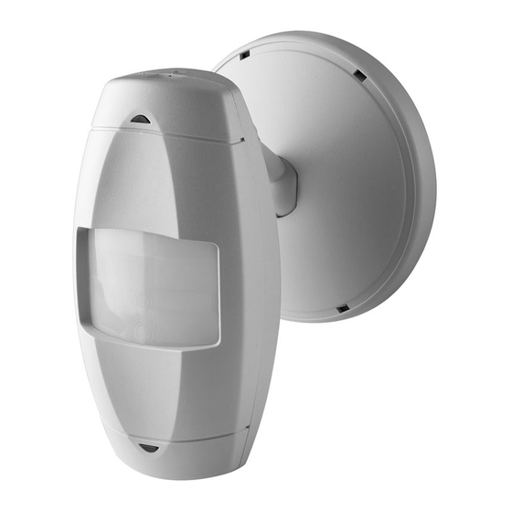
Infrared Wall Mounted Occupancy Sensor
Cat. Nos. OSWHB-I, OSWLR-I, OSWWV-I
To be used with 24VDC OSPxx Series, OPB15, miniZ and CN100 Power Pack Class II Low-Voltage Wiring
INSTALLATION INSTRUCTIONS
Catalog No.
OSWHB-I0W
OSWLR-I0W
OSWWV-I0W
Step 3 cont'd
4. Install the mounting base of the wall sensor to the wallboard or ceiling using the
included screws, nuts and washers.
5. Pass wires through the base cover/neck assembly (refer to Mounting Option
diagram A).
6. Class II Wiring: Connect low-Voltage wires from Power Pack to Sensor per
WIRING DIAGRAM as follows: Twist strands of each lead tightly and, with circuit
conductors, push firmly into appropriate wire connector. Screw connectors on
clockwise making sure that no bare conductor shows below the wire connectors.
Secure each connector with electrical tape.
7. Push wire connections through the center hole of the back cover and into the wall
or ceiling.
8. Snap neck and base cover onto mounting base in the desired orientation. Align
arrows on mounting base and base cover, push on and turn to lock base cover to
mounting base.
9. Push wires through the hole and begin to fasten the plastic nut around the back
of the sensor body. Move the sensor body to the desired orientation and then
continue to tighten the nut around the sensor body. NOTe: The neck is a two
position assembly with catches to hold it in position for either ceiling or wall
mounting.
10. Restore power at circuit breaker or fuse to Power Pack. INSTALLATION IS
COMPLeTe.
Mounting Option diagram A
Occupancy Sensor Mounted to Wallboard Using Screws
Mounting Screws
(2 places)
Plastic Nut
Low-Voltage
Sensor
Wires
Wallboard
Base Cover/
Neck Assembly
Occupancy Sensor Mounted to Wallboard or
drop Ceiling Using Screws, Nuts and Washers
Low-Voltage
Mounting
Wires
Screw, Nut and
(2 places)
Washer
(2 places)
Drop Ceiling
Mounting Base
Base Cover
Mounting Base
Plastic Nut
Sensor
CATALOG ITeMS
Current
description
Consumption
Coverage
High Bay
20mA
55 ft. mounted at 30 ft
Long Range
20mA
100 ft. mounted at 10 ft.
Wide View
20mA
2500 sq. ft.
Step 3 cont'd
B. Wall or Ceiling Using Junction Box or Surface Mount Raceway
Installation (refer to Mounting diagrams):
NOTe: You may use the mounting screws, nuts and washers included, or screws in
combination with commercially available wall anchors.
NOTe: Listed below are suggested JUNCTION BOx installation applications which
require mounting to conduit in one of the following ways.
Mounting Option diagram B
Occupancy Sensor Mounted to Octagon
Box Installed flush to Wallboard
Octagon Box
4" x 1 1/2" deep
Mounting Screws (2 places)
Mounting Base
Base Cover
Wallboard
Occupancy Sensor Mounted to Octagon
Box Installed flush to Wallboard Ceiling or drop Ceiling
4" Octagon
Screws
Raised Cover
Wallboard Ceiling
4" Octagon
Raised Cover
Sensor
fCC COMPLIANCe STATeMeNT:
his device complies with part 15 of the FCC rules. Operation is subject to the following two conditions: (1)
T
This device must not cause harmful interference, and (2) This device must accept any interference received,
including interference that may cause undesired operation.
Step 3 cont'd
Occupancy Sensor Mounted to Wallboard
Using Round fixture with Raceway
Wire Mold Round fixture
Box Cat. No. 5738
(for raceway mount)
Wire Mold
Back Cover
Wallboard
Sensor
C. OPB15 Power Base Installation:
In addition to the regular mounting methods shown, the OSWxx can be mounted to the
OPB15 Power Base.
1. Install the OPB15 per the installation sheet included with the OPB15.
2. Remove the OSWxx from the box and pass the low-voltage wires through the
neck/base cover assembly.
3. Screw the neck plastic nut to the sensor body to hold assembly together while
connecting the wire leads.
4. Remove the two-part
connector from the
OPB15 noting the
orientation it was in
Octagon Box
before removal.
4" x 1 1/2" deep
5. Connect the wires
from the sensor to the
appropriate locations
on the terminal block.
Mounting Base
6. Push the terminal block
on to the OPB15 pins.
Base Cover
7. Align the raised arrow
on the side of the base
cover with the arrow on
the mounting ring of the
OPB15 and push on
and twist to install.
8. Rotate the assembly
and adjust the neck for
either ceiling or wall
configuration aiming
per the diagram.
9. Tighten the plastic nut
on the neck to lock the
position of the sensor.
PK-93596-10-00-2C
Mounting Screws for Wire Mold fixture (2 places)
Base Cover
Mounting Base
Wire Mold Raceway
Sensor
4" Octagon 2.125" Deep
Electrical Box
8-32 Screws
(2 places)
Sensor
Power Base
Two-Part
Terminal
Connector
Base Cover
Sensor
Advertisement

Subscribe to Our Youtube Channel
Related Manuals for Leviton OSWHB-I Series


Summary of Contents for Leviton OSWHB-I Series
- Page 1 Infrared Wall Mounted Occupancy Sensor Cat. Nos. OSWHB-I, OSWLR-I, OSWWV-I To be used with 24VDC OSPxx Series, OPB15, miniZ and CN100 Power Pack Class II Low-Voltage Wiring INSTALLATION INSTRUCTIONS WARNINGS ANd CAUTIONS: CATALOG ITeMS PK-93596-10-00-2C • To be installed and/or used in accordance with appropriate electrical codes and regulations. Current •...
- Page 2 There are no other or implied warranties of any kind, including merchantability and fitness for a particular purpose, but if any implied warranty is required by the applicable jurisdiction, the duration of any such implied warranty, including merchantability and fitness for a particular purpose, is limited to five years.
Need help?
Do you have a question about the OSWHB-I Series and is the answer not in the manual?
Questions and answers