Advertisement
Quick Links
DI-102-OSW12-00A
WARNINGS AND CAUTIONS:
• To be installed and/or used in accordance with appropriate electrical codes and regulations.
• If you are unsure about any part of these instructions, consult a qualified electrician.
• Sensors must be mounted on a vibration free surface.
• All sensors must be mounted at least 6 feet away from air vents.
• Do not mount sensors closer than 10 feet from each other.
• Do not touch the surface of the lens. Clean outer surface with a damp cloth only.
Tools needed to install your Sensor:
Slotted/Phillips Screwdriver
Electrical Tape
Pliers
Pencil
Cutters
Parts Included List:
Sensor (1)
#8-32 x 1/2" Screw (2)
#8-32 x 1-1/2" Screw (2)
#8-32 Washer and Nut (2)
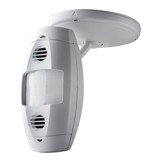
DESCRIPTION
The Occupancy Sensor is a low-voltage infrared and ultrasonic sensor that works with
the OSP xx Series and CN100 power pack to automatically control lighting. The sensor
turns the lights on and keeps them on whenever occupancy is detected and will turn
them off after the 'delayed-off time' has expired.
The sensor continually analyzes and adjusts to changing conditions. The sensor uses
the latest microprocessor-based technology which permits it to continually adjust and
optimize its performance.
The combination of ultrasonic (doppler shift) motion detection which gives maximum
sensitivity and infrared motion detection which gives higher false triggering immunity
yields a sensor with excellent performance.
INSTALLING YOUR OCCUPANCY SENSOR
√
NOTE: Use check boxes
when Steps are completed.
WARNING:
Step 1
TO AVOID FIRE, SHOCK, OR DEATH; TURN OFF POWER
at circuit breaker or fuse and test that power is off before wiring!
OFF
ON
OFF
ON
OFF
ON
OFF
ON
OFF
ON
OFF
ON
OFF
ON
OFF
ON
OFF
ON
OFF
ON
OFF
ON
OFF
ON
Preparing and connecting wires:
Step 2
1/2"
(1.3 cm)
Cut
(if necessary)
Strip Gage (measure
bare wire here
Typical Installations:
Step 3
Listed are 2 typical installation options (A and B). Choose one that best suits
your needs. Other methods of installation may be possible but they have not
been described here. Note that the wall sensor can be wall mounted or ceiling
mounted simply by rotating the neck. This gives greater flexibility in attaining
the desired coverage.
A. Wall or Ceiling Installation Using Screws (Mounting Option A):
NOTE: You may use the mounting screws, nuts and washers included, or screws in
combination with commercially available wall anchors.
1. Select location for mounting of sensor for your application (refer to
Mounting Location Diagram).
2. Make a hole in the wallboard or ceiling large enough to pass the wire
connections and wire nuts through (approximately 1" diameter).
3. Drill holes for mounting screws using mounting bracket as template.
Multi-Technology Wall Mounted Occupancy Sensor
To be used with 24VDC OSP xx Series and CN100 Power Pack Class II Low-Voltage Wiring
INSTALLATION INSTRUCTIONS
Catalog No.
OSW12-M0W
Multi-Technology
Step 3 cont'd
4. Install the mounting bracket of the wall sensor to the wallboard or ceiling
using the included screws, nuts and washers.
5. Pass wires through the base cover/neck assembly (refer to Mounting
Option Diagram A).
6. Class II Wiring: Connect low-Voltage wires from Power Pack to Sensor per
WIRING DIAGRAM as follows: Twist strands of each lead tightly and, with
circuit conductors, push firmly into appropriate wire connector. Screw
connectors on clockwise making sure that no bare conductor shows below
the wire connectors. Secure each connector with electrical tape.
7. Push wire connections through the center hole of the back cover and into the
wall or ceiling.
8. Snap neck and base cover onto mounting bracket in the desired orientation.
9. Push wires through the hole and begin to fasten the plastic nut around the
back of the sensor body. Move the sensor body to the desired orientation and
then continue to tighten the nut around the sensor body.
10. Restore power at circuit breaker or fuse to Power Pack. INSTALLATION IS
COMPLETE.
Mounting Option Diagram A
Occupancy Sensor Mounted to Wallboard Using Screws
Mounting Screws
(2 places)
Plastic Nut
Low-Voltage
Wires
Sensor
Wallboard
Base Cover/
Neck Assembly
Occupancy Sensor Mounted to Wallboard or
Drop Ceiling Using Screws, Nuts and Washers
Low-Voltage
Wires
Screw, Nut and
Mounting Screws
Washer
(2 places)
(2 places)
Drop Ceiling
Mounting Base
Base Cover
Mounting Base
(top view)
Plastic Nut
Sensor
Cat. No. OSW12-M
CATALOG ITEMS
Current
Operating
Description
Consumption
Frequency
Coverage
30mA
32KHz
1200 sq. ft
Step 3 cont'd
B. Wall or Ceiling Using Junction Box or Surface Mount Raceway
Installation (refer to Mounting Diagrams):
NOTE: You may use the mounting screws, nuts and washers included, or screws in
combination with commercially available wall anchors.
NOTE: Listed below are suggested JUNCTION BOX installation applications which
require mounting to conduit in one of the following ways:
Mounting Option Diagram B
Occupancy Sensor Mounted to Octagon
Box Installed Flush to Wallboard
Octagon Box
4" x 1 1/2" deep
Mounting Screws (2 places)
Wallboard
Occupancy Sensor Mounted to Octagon
Box Installed Flush to Wallboard Ceiling or Drop Ceiling
Octagon Box
4" 1 1/2" deep
4" Octagon
Raised Cover
Wallboard Ceiling
4" Octagon
Raised Cover
FCC COMPLIANCE STATEMENT:
T
his device complies with part 15 and part 18 of the FCC rules. Operation is subject to the following two
conditions: (1) This device must not cause harmful interference, and (2) This device must accept any
interference received, including interference that may cause undesired operation.
Step 3 cont'd
Occupancy Sensor Mounted to Wallboard
Using Round Fixture with Raceway
Wire Mold Round Fixture
Box Cat. No. 5738
(for raceway mount)
Wire Mold
Back Cover
Wallboard
OPERATION
• Multi-Tech Mode – This is the default mode of operation for the sensor. PIR
technology turns lights on in this mode; however, motion detection by either
technology will keep the lights on. If neither technology detects motion, the lights
turn off after the delayed-off time.
• Single-Tech Mode – Only one technology is active in this mode. The technology
is selected by the dip switches. Motion detection by the selected technology - PIR
or ultrasonic - will turn on the lights as well as keep them on. When motion is not
detected, the lights will turn off after the delayed-off time.
• Delayed-Off time – The sensor is designed to turn the lights off if no motion is
detected after a specified time. This length of time is called the delayed-off time
Mounting Base
and is set using the timer (Black) knob on the sensor. The adapting patterns will
modify the delayed-off time to fit the parameters of each installation based on
environmental conditions and occupancy patterns.
• Walk-through Mode – The walk-through feature is useful when a room is
momentarily occupied. With this feature, the sensor will turn the lights off shortly
after the person leaves the room.
The walk-through feature works as follows: When a person enters the room, the
lights will turn on. If the person leaves the room before the default walk-through
time-out of 2.5 minutes, the sensor will turn the lights off. If the person stays in the
room for longer than 2.5 minutes, the sensor will proceed to the standard
operation.
• LED Operation – There are two LED indicators that will flash when motion is
detected. The LED flash can be disabled using the LED disable switch setting
(refer to Table 2). Green flash indicates motion detection by ultrasonic technology.
Red flash indicates motion detection by infrared technology.
Mounting Screws for Wire Mold Fixture (2 places)
Wire Mold Raceway
Advertisement

Subscribe to Our Youtube Channel
Related Manuals for Leviton OSW12-MNW


Summary of Contents for Leviton OSW12-MNW
- Page 1 Multi-Technology Wall Mounted Occupancy Sensor Cat. No. OSW12-M To be used with 24VDC OSP xx Series and CN100 Power Pack Class II Low-Voltage Wiring DI-102-OSW12-00A INSTALLATION INSTRUCTIONS WARNINGS AND CAUTIONS: FCC COMPLIANCE STATEMENT: CATALOG ITEMS • To be installed and/or used in accordance with appropriate electrical codes and regulations. his device complies with part 15 and part 18 of the FCC rules.
- Page 2 Leviton Manufacturing Co., Inc., Att: Quality Assurance Department, 59-25 Little Neck Parkway, Little Neck, New York 11362-2591. This warranty excludes and there is disclaimed liability for labor for removal of this product or reinstallation.
- Page 3 FOLD SCHEME 17.0¨ Cat. No. LEVITON INSTRUCTION SHEET/MANUAL LEVITON INSTRUCTION SHEET/MANUAL 11.0¨ SPECIFICATIONS SPECIFICATIONS DI-102-OSW12-00A Black Helvetica 50 Lb. offset Paper size: Paper size: 17" X 11" Overall size: Overall size: 2.83" X 3.67" Final fold size: Final fold size: Cat.
Need help?
Do you have a question about the OSW12-MNW and is the answer not in the manual?
Questions and answers