Table of Contents
Advertisement
Quick Links
Evaluation Board Manual
Features
Reference design layout for easy system integration
Low-cost 6-layer PCB with 1 oz. copper traces
Fully assembled with test points and stand-offs
User-friendly switches (jumper-free)
Single input operation with mini-USB
USB to I
C hardware converter for PC connectivity
2
EEPROM to store and load start-up script
Software tool for full register and settings control
Optional DC power adapter input for high power
applications
LED status indicators for most inputs and outputs
Thermal vias below package for improved heat
dissipation
Evaluation Kit Contents
Evaluation board
3.7V Li+ battery
USB type A to mini-USB type B cable
AC to DC power adapter
2pcs 3.5mm male to male stereo cable
4Ω portable speaker
IDTP95020-EVAL evaluation board manual
IDTP95020 product datasheet
CD containing:
- IDTP95020 control software tool
- Reference layout Gerber Files
- Reference layout Cadence Allegro board files
- Electronic copy of IDTP95020 product datasheet
- Electronic copy of IDTP95020-EVAL manual
December 13, 2010
Audio, Power Management,
IDTP95020-EVAL
Description
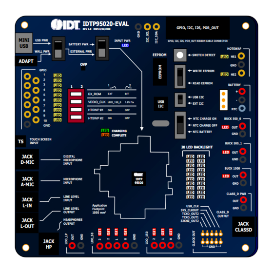
The IDTP95020 evaluation board serves to demonstrate
the features and performance of the IDTP95020 Audio,
Power Management and Control integrated circuit. The
intuitive top-level layout and control switches simplify the
user experience to emphasize the impressive level of
integration and abundance of useful features that this
device offers.
The device can be powered and controlled by a single
mini-USB input. If more input power is required, a DC
input from wall adapter can be connected.
The external EEPROM memory chip is pre-programmed
with a basic start-up script that is automatically loaded
when power is applied. The device can be reprogrammed
to suit the needs of your specific application using the
IDTP92020 software tool.
The core layout is a 6-layer reference that can be copied
and integrated into a larger system design.
Evaluation Board
IDTP95020-EVAL
IDTP95020-EVAL
IDTP95020-EVAL
IDTP95020-EVAL
REV 1.0 NWS 8/02/2010
REV 1.0 NWS 8/02/2010
REV 1.0 NWS 8/02/2010
REV 1.0 NWS 8/02/2010
MINI
MINI
USB PWR
USB PWR
BATTERY PWR
BATTERY PWR
USB
USB
WALL PWR
WALL PWR
EXTERNAL PWR
EXTERNAL PWR
ADAPT
ADAPT
OVP
OVP
OVP
OVP
GPIO
GPIO
1
1
1
1
LED
LED
LED
LED
LED
LED
LED
LED
2
2
2
2
3
3
3
3
LED
LED
LED
LED
1
1
1
1
2
2
2
2
1
1
LED
LED
LED
LED
4
4
4
4
EX_ROM
EX_ROM
EX_ROM
EX_ROM
LED
LED
LED
LED
EXT
EXT
5
5
5
5
LED
LED
LED
LED
6
6
6
6
VDDIO_CLK
VDDIO_CLK
VDDIO_CLK
VDDIO_CLK
LDO_150_0
LDO_150_0
LED
LED
LED
LED
7
7
7
7
LED
LED
LED
LED
8
8
8
8
HTSWP #1
HTSWP #1
HTSWP #1
HTSWP #1
ON
ON
LED
LED
LED
LED
9
9
9
9
HTSWP #2
HTSWP #2
HTSWP #2
HTSWP #2
ON
ON
LED
LED
LED
LED
10
10
10
10
GND
GND
GND
GND
LED
LED
LED
LED
LED
LED
LED
LED
TOUCH SCREEN
TOUCH SCREEN
TS
TS
INPUT
INPUT
JACK
JACK
DIGITAL
DIGITAL
MICROPHONE
MICROPHONE
D-MIC
D-MIC
INPUT
INPUT
JACK
JACK
MICROPHONE
MICROPHONE
INPUT
INPUT
A-MIC
A-MIC
LINE LEVEL
LINE LEVEL
JACK
JACK
INPUT
INPUT
L-IN
L-IN
Application
Application
LINE LEVEL
LINE LEVEL
Footprint
Footprint
OUTPUT
OUTPUT
1050 mm
1050 mm
2
2
JACK
JACK
HEADPHONES
HEADPHONES
OUTPUT
OUTPUT
L-OUT
L-OUT
JACK
JACK
HP
HP
Figure 1. Evaluation Board Illustration Top Layer
1
and Control
GPIO, I2C, I2S, POR_OUT
GPIO, I2C, I2S, POR_OUT
INPUT PWR
INPUT PWR
GPIO, I2C, I2S, POR_OUT RIBBON CABLE CONNECTOR
GPIO, I2C, I2S, POR_OUT RIBBON CABLE CONNECTOR
LED
LED
EEPROM
EEPROM
SWITCH DETECT
SWITCH DETECT
LED
WRITE EEPROM
WRITE EEPROM
LED
READ EEPROM
READ EEPROM
1
1
2
2
2
2
EXT
EXT
INT
INT
INT
INT
USB I2C
USB I2C
USB
USB
1.8V Fix
1.8V Fix
LDO_150_0
LDO_150_0
1.8V Fix
1.8V Fix
EXT I2C
EXT I2C
I2C
I2C
ON
ON
OFF
OFF
OFF
OFF
NTC CHARGE ON
NTC CHARGE ON
ON
ON
OFF
OFF
OFF
OFF
NTC CHARGE OFF
NTC CHARGE OFF
CHARGING
CHARGING
CHARGING
CHARGING
NTC BATTERY
NTC BATTERY
COMPLETE
COMPLETE
COMPLETE
COMPLETE
20 LED BACKLIGHT
20 LED BACKLIGHT
20 LED BACKLIGHT
20 LED BACKLIGHT
LED
LED
LED
LED
LED
LED
LED
LED
LED
LED
LED
LED
LED
LED
LED
LED
LED
LED
LED
LED
LED
LED
LED
LED
LED
LED
LED
LED
LED
LED
LED
LED
LED
LED
LED
LED
LED
LED
LED
LED
LED
LED
LED
LED
LED
LED
LED
LED
LED
LED
LED
LED
LED
LED
LED
LED
LED
LED
LED
LED
LED
LED
LED
LED
LED
LED
LED
LED
LED
LED
LED
LED
IDTP
IDTP
IDTP
IDTP
IDTP
IDTP
95020
95020
95020
95020
95020
95020
LED
LED
LED
LED
LED
LED
LED
LED
LED
LED
LED
LED
LED
LED
LED
LED
LED
LED
LED
LED
LED
LED
LED
LED
LED
LED
LED
LED
LED
LED
LED
LED
LED
LED
LED
LED
LED
LED
LED
LED
LED
LED
LED
LED
LED
LED
LED
LED
USB_CLK
USB_CLK
SYS_CLKOUT
SYS_CLKOUT
CLASS_D
CLASS_D
TCXO_OUT2
TCXO_OUT2
OUTPUT
OUTPUT
TCXO_OUT1
TCXO_OUT1
32KHZ_OUT2
32KHZ_OUT2
GND
GND
HOTSWAP
HOTSWAP
LED
HS1
HS1
GND
GND
LED
HS2
HS2
BATTERY
BATTERY
+
+
-
-
NTC
NTC
BUCK 500_0
BUCK 500_0
LED
LED
OUT
OUT
GND
GND
BUCK 500_1
BUCK 500_1
LED
LED
OUT
OUT
GND
GND
BUCK 1000
BUCK 1000
LED
LED
OUT
OUT
GND
GND
CLASS_D PWR
CLASS_D PWR
OUT
OUT
GND
GND
JACK
JACK
CLASSD
CLASSD
Advertisement
Table of Contents

Related Manuals for Renesas IDTP95020-EVAL


Summary of Contents for Renesas IDTP95020-EVAL
- Page 1 LDO_150_0 1.8V Fix 1.8V Fix LDO_150_0 LDO_150_0 1.8V Fix 1.8V Fix EXT I2C EXT I2C - Electronic copy of IDTP95020-EVAL manual HTSWP #1 HTSWP #1 HTSWP #1 HTSWP #1 NTC CHARGE ON NTC CHARGE ON BUCK 500_0 BUCK 500_0 HTSWP #2...
-
Page 2: Table Of Contents
IDTP95020-EVAL Evaluation Board Manual Table of Contents Usage Guide ..............3 Four-Switch Dip Switch ..........11 Quick-Start Guide ............3 Clock Outputs ............. 12 Verifying Connectivity ........... 3 AC to DC Wall Adapter ..........12 Factory Settings ............4 LED Backlight ............. 12 Installing the Software Drivers ........ -
Page 3: Usage Guide
Figure 2. Verifying Connectivity 3. Plug the AC adapter into the wall (120 VAC) and connect the other end (4.5 VDC) into the adapter plug on the IDTP95020-EVAL board. 4. Open the CyrusTool to change register settings and control the device. -
Page 4: Factory Settings
Installing the Software Drivers The EEPROM on the IDTP95020-EVAL board is pre- The first time that you use the IDTP95020-EVAL board, programmed with a generic start-up script to facilitate the you must install the drivers to communicate with the USB speedy evaluation of the device. - Page 5 IDTP95020-EVAL Evaluation Board Manual Add or Remove Scripts Running The Script Click the ‘Add Scripts’ button to choose which scripts you Once you have added the script(s) that you want to run, want to run. If you add more than one script they will run in click the ‘Run’...
-
Page 6: Creating A Custom Power-On Sequence
Follow this process until you have configured all of the system. The IDTP95020-EVAL CD includes the CyrusTool regulators that you want to turn on when power is first which will enable you to generate a custom power-on applied to the device. -
Page 7: Programming The Eeprom Script
IDTP95020-EVAL Evaluation Board Manual Programming the EEPROM Script The IDTP95020-EVAL is equipped with an EEPROM chip that stores an initial start-up script that the IDTP95020 device loads at start-up. In a typical application, the IDTP95020 is configured by the application processor or can be mask programmed with a custom script inside the IDTP95020 device itself. - Page 8 Evaluation Board Manual Generating the Binary File Downloading the Binary File to EEPROM The EEPROM chip requires a binary (.BIN) file be loaded. After creating the binary file, the software tool will assume The IDTP95020 software tool has a function to convert that you want to load the binary file that you just created, a .TXT script file into a .BIN file.
-
Page 9: Changing Register Settings
Changing Register Settings While there are several demonstration scripts included on Figure 18. Changing the Register Setting the IDTP95020-EVAL CD in the /Software/Scripts directory, it is often useful to change the individual register After pressing the ‘Write’ button, your changes will take bits to further evaluate the capabilities of the IDTP95020 effect immediately. -
Page 10: External I 2 C Input Switch
Evaluation Board Manual Manually Enabling and Setting the DC DC Regulators External I C Input Switch The five switching regulators and seven LDO regulators This evaluation board provides three options to control the have each have a global and local disable bit. Both bits IDTP95020 I C: using your computer’s USB cable, an must be high for each regulator to be enabled. -
Page 11: Setting The Battery Ntc Mode
IDTP95020-EVAL Evaluation Board Manual Setting the Battery NTC Mode Four-Switch Dip Switch There are three modes for the battery temperature The four-switch dip switch offers control for the EX_ROM sensing (NTC) function. pin, the VDDIO_CLK pin, and both hotswap channels. -
Page 12: Clock Outputs
Evaluation Board Manual Clock Outputs LED Backlight The IDTP95020 evaluation board has probe points for the The IDTP95020 is equipped with 20 white LEDs to various clock signal outputs. Each of the five outputs have simulate an LED backlight application. To demonstrate a small probe-hole and larger through-hole for each signal this feature, follow these steps: and ground. -
Page 13: Audio Output (Class_D)
IDTP95020-EVAL Evaluation Board Manual Audio Output (CLASS_D) such as your portable MP3 player. Then, connect the CLASS_D Output to the speaker using the other 3.5mm The IDTP95020 will take an audio input from your PC (or audio cable. Refer to Figure 25 for an illustration. -
Page 14: Schematic
Evaluation Board Manual SCHEMATIC Figure 26. Board Schematic Page 1 December 13, 2010... - Page 15 IDTP95020-EVAL Evaluation Board Manual BUCK500_0_OUT BUCK500_1_OUT BUCK1000_OUT 12PF GPIO, ADC, AUDIO MISC 100uF DNP 100uF 1.2K Figure 27. Board Schematic Page 2 December 13, 2010...
-
Page 16: Component Map
Evaluation Board Manual COMPONENT MAP Figure 28. Component Map December 13, 2010... - Page 17 IDTP95020-EVAL Evaluation Board Manual SYMBOL VALUE DESCRIPTION PART NUMBER LOCATION BUCK1000 Red TP Buck1000 output 5010 (red) BUCK500_0 Red TP Buck500_0 output 5010 (red) BUCK500_1 Red TP Buck500_1 output 5010 (red) 1µF Input current limit sense filter capacitor for GRM155R61A105KE15D CHRG_CLSEN pin 2.2µF...
- Page 18 IDTP95020-EVAL Evaluation Board Manual SYMBOL VALUE DESCRIPTION PART NUMBER LOCATION 1µF LDO_150_2 output capacitor C0603X7R100-105KN 1µF LDO_150_1 output capacitor C0603X7R100-105KN 1µF LDO_150_0 output capacitor C0603X7R100-105KN 12pF 32kHz crystal filter capacitor C0402C120J5GACTU 12pF 32kHz crystal filter capacitor C0402C120J5GACTU 1µF VDD18_CAP filter capacitor...
- Page 19 IDTP95020-EVAL Evaluation Board Manual SYMBOL VALUE DESCRIPTION PART NUMBER LOCATION 1uF / 50V LED_Boost output capacitor GRM21BR71H105KA12L 0.1µF Buck_500_1 output decoupling capacitor ECJ-1VB1C104K 0.1µF Buck_1000 output decoupling capacitor ECJ-1VB1C104K 1µF OVP protection switch input capacitor C0603X7R100-105KN 2.2µF Line-level out AC coupling capacitor...
- Page 20 IDTP95020-EVAL Evaluation Board Manual SYMBOL VALUE DESCRIPTION PART NUMBER LOCATION GPIO9 Yellow TP GPIO9 input or output 5014 (yellow) Headphones 3.5mm output jack SJ1-3523N HS_O1 Yellow TP Hotswap #1 output 5014 (yellow) HS_O2 Yellow TP Hotswap #2 output 5014 (yellow)
- Page 21 IDTP95020-EVAL Evaluation Board Manual SYMBOL VALUE DESCRIPTION PART NUMBER LOCATION LED25 Yellow LED GPIO10 output voltage indicator LTST-C170YKT LED26 Yellow LED GPIO9 output voltage indicator LTST-C170YKT LED27 Yellow LED Hotswap #1 output voltage indicator LTST-C170YKT LED28 Yellow LED Hotswap #2 output voltage indicator...
- Page 22 Evaluation Board Manual SYMBOL VALUE DESCRIPTION PART NUMBER LOCATION 10kΩ USB to I C chip pull up resistor ERJ-3EKF1002V 10kΩ USB to I C chip pull up resistor ERJ-3EKF1002V 1.2kΩ LED5 current limiting resistor ERJ-3EKF1201V 680Ω LED10 current limiting resistor ERJ-3GEYJ681V 680Ω...
- Page 23 IDTP95020-EVAL Evaluation Board Manual SYMBOL VALUE DESCRIPTION PART NUMBER LOCATION OPEN (680Ω) LED26 current limiting resistor ERJ-3GEYJ681V 680Ω LED27 current limiting resistor ERJ-3GEYJ681V 680Ω LED28 current limiting resistor ERJ-3GEYJ681V 10kΩ CHRG_NTC pull up resistor to CHRG_VNTC ERJ-2GEJ103X Push-button SW_DET push button pull-up switch...
-
Page 24: Ordering Guide
Evaluation Board Manual ORDERING GUIDE Table 1. Ordering Summary PART NUMBER MARKING PRICE AMBIENT TEMP. SHIPPING CARRIER QUANTITY RANGE IDTP95020-EVAL IDTP95020-EVAL $249.00 0°C to +70°C Box 14”x10”x2” NOTES:... - Page 25 Renesas' products are provided only subject to Renesas' Terms and Conditions of Sale or other applicable terms agreed to in writing. No use of any Renesas resources expands or otherwise alters any applicable warranties or warranty disclaimers for these products.
Need help?
Do you have a question about the IDTP95020-EVAL and is the answer not in the manual?
Questions and answers