Table of Contents
Advertisement
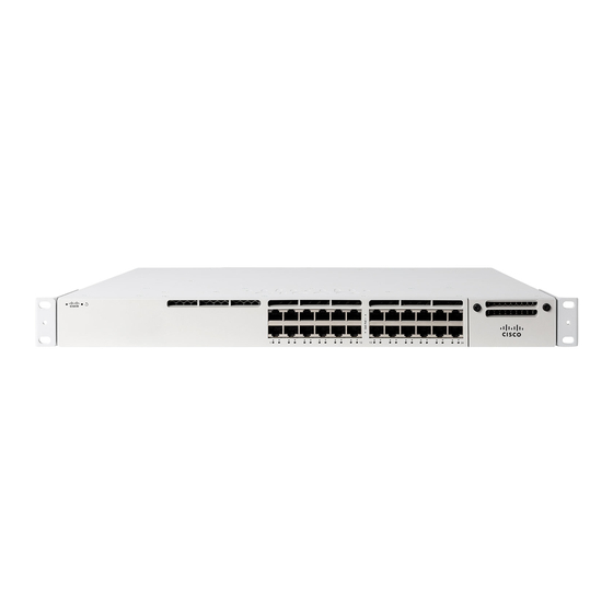
MS390 Series Installation Guide
About this Guide
This guide provides instruction on how to install and configure your MS390 series switch. This guide also provides mounting instructions and limited
troubleshooting procedures. For more switch installation guides, refer to the
Product Overview
Models
Model number
MS390-24-HW
MS390-24P-HW
MS390-24U-HW
MS390-24UX-HW
MS390-48-HW
MS390-48P-HW
MS390-48U-HW
MS390-48UX-HW
switch installation guides section
Stackable Layer-3 24-port Gbe switch with 10G/40G modular uplinks, hot-swappable power
supplies and hot-swappable fans
Stackable Layer-3 24-port Gbe POE+ switch with 10G/40G modular uplinks, hot-swappable power
supplies and hot-swappable fans
Stackable Layer-3 24-port Gbe UPOE switch with 10G/40G modular uplinks, hot-swappable power
supplies and hot-swappable fans
Stackable Layer-3 24-port mGbe UPOE switch with 10G/40G modular uplinks, hot-swappable
power supplies and hot-swappable fans
Stackable Layer-3 48-port Gbe switch with 10G/40G modular uplinks, hot-swappable power
supplies and hot-swappable fans
Stackable Layer-3 48-port Gbe POE+ switch with 10G/40G modular uplinks, hot-swappable power
supplies and hot-swappable fans
Stackable Layer-3 48-port Gbe UPOE switch with 10G/40G modular uplinks, hot-swappable power
supplies and hot-swappable fans
Stackable Layer-3 36-port 2.5Gbe and 12-port mGbe UPOE switch with 10G/40G modular uplinks,
hot-swappable power supplies and hot-swappable fans
on our documentation website.
Description
1
Advertisement
Table of Contents

Subscribe to Our Youtube Channel
Related Manuals for Cisco MERAKI MS390 Series


Summary of Contents for Cisco MERAKI MS390 Series
- Page 1 MS390 Series Installation Guide About this Guide This guide provides instruction on how to install and configure your MS390 series switch. This guide also provides mounting instructions and limited troubleshooting procedures. For more switch installation guides, refer to the switch installation guides section on our documentation website.
-
Page 2: Technical Specifications
Stackable Layer-3 48-port 5Gbe UPOE switch with 10G/40G modular uplinks, hot-swappable MS390-48UX2-HW power supplies and hot-swappable fans Technical Specifications • Each model has 1 dedicated management interface • Each model has two 120G stack ports • Each of the model has modular uplinks where you can choose from 3 different options of 10G and 40G SFP+ and QSFP+ uplink modules •... -
Page 3: Front Panel Components
Front Panel Components Item Component LED Status Description Restore Restore button to clear switch IP and local configuration settings Power LED Solid amber Switch is unable to connect to the Meraki cloud or it is in the inital stage of boot-up process Cycling through different colors Management plane is initializing and the switch initiates communication to Meraki cloud Solid white... - Page 4 Stack Cables are connected here Redundant Fans Green Active and operational StackPower Ports StackPower cables are connected here Power Supplies Green Active and functional power supplies MS390 Series Front and Back Panel MS390-24 Series front panel MS390-24P Series front panel...
- Page 5 MS390-24U Series front panel MS390-24UX Series front panel MS390-48 Series front panel MS390-48P Series front panel MS390-48U Series front panel MS390-48UX Series front panel MS390-48UX2 Series front panel...
-
Page 6: Factory Reset Button
MS390 Series Back Panel Factory Reset Button If the button is pressed and held for at least 10 to 15 seconds and then released, the switch will reboot and be restored to its original factory settings by deleting all configuration information stored on the unit. -
Page 7: Safety And Warnings
In addition to the MS switch, the following are provided: • 2 x (19 inch) Mounting brackets and screw kit that includes: ◦ 8 x Flat-head screws ◦ 4 x number-12 pan-head screws ◦ 4 x number-10 pan-head screws ◦ 1 x (4 x 20 mm) pan-head screw ◦... -
Page 8: Assigning An Ip Address
Ensure that the switch network is set to the correct firmware version. As of September 9th, 2020 MS 12.28 is the recommended version. Recommended versions are subject to change. You can refer to Managing Firmware Upgrades for steps to set network firmware to the desired version. Check and Configure Upstream Firewall Settings If a firewall is in place, it must allow outgoing connections on particular ports to particular IP addresses. -
Page 9: Installation Instructions
Ensure the upstream switch/router port is configured properly and there is no VLAN mismatch. Check STP configuration MS390 series switches run a single instance of MST out of the box. Please refer to this document for interoperability. Device reboot/ reset precaution After powering on the unit or a device reboot, the power LED goes through the following cycle - 1. - Page 10 2. Align the rack mount brackets on the sides of the switch onto the rack.
- Page 11 3. Secure and screw in the rack mount bracket on to the rack.
- Page 12 4. Insert the Uplink module.
- Page 13 Stack Cabling Installation • Connect the cable to the stack port on the switch back panel (as shown in the back panel diagram). Align the connector and connect the stack cable to the stack port on the switch back panel and finger-tighten the screws (clockwise direction).
-
Page 14: Basic Troubleshooting
If you are still experiencing hardware issues, please contact Cisco Meraki support by logging in to dashboard and using the Help option near the top of the page, then opening and email case or calling using the contact information on that page. - Page 15 If your Cisco Meraki device fails and the problem cannot be resolved by troubleshooting, contact support to address the issue. Once support determines that the device is in a failed state, they can process an RMA and send out a replacement device free of charge. In most circumstances, the RMA will include a pre-paid shipping label so the faulty equipment can be returned.
- Page 16 permissible temperature and humidity ranges during storage are specified in the Operation (Installation) Manual. • Transportation of equipment should be carried out in the original packaging in covered vehicles by any means of transport. The temperature and humidity during transportation must comply with the permissible established ranges of temperature and humidity during storage (in the off state) specified in the Operation Manual (Installation).
Need help?
Do you have a question about the MS390 Series and is the answer not in the manual?
Questions and answers