Table of Contents
Advertisement
MS450 Series Installation Guide
About this Guide
This guide provides instruction on how to install and configure your MS450 series switch. This guide also provides mounting instructions and limited
troubleshooting procedures. For more switch installation guides, refer to the
Models
Model number
Description
Layer-3 12-port 40GbE QSFP+ aggregation switch with two 100GbE QSFP28 ports and 1 management interface, hot-
MS450-12
swappable power supplies / fans
Product Overview
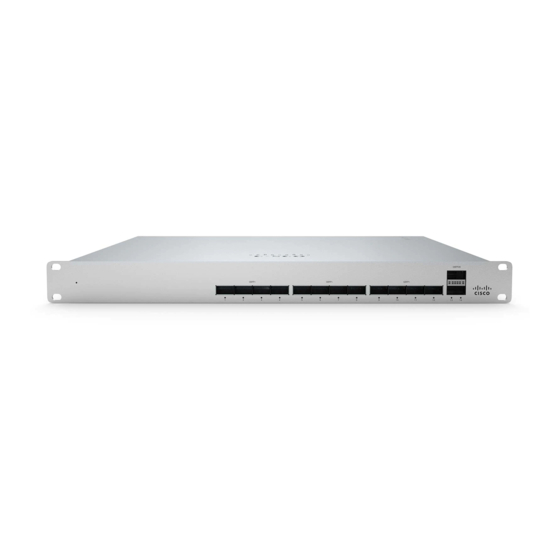
Physical Specifications
40GbE QSFP+
100Gbe QSFP28 uplink ports
100G Hardware Stack Port
Dedicated Mgmt Interface
Hot Swap Power Supply
Hot Swap Fans
Power Input
Power Consumption
Operating Temperature
switch installation guides section
on our documentation website.
MS450-12
12
2
2
1
Yes, Dual
Yes, 3x
100 - 240 VAC, 47-63 Hz
47-138W
32°F - 113 °F
0°C - 45 °C
1
Advertisement
Table of Contents

Related Manuals for Cisco MERAKI MS450 Series


Summary of Contents for Cisco MERAKI MS450 Series
- Page 1 MS450 Series Installation Guide About this Guide This guide provides instruction on how to install and configure your MS450 series switch. This guide also provides mounting instructions and limited troubleshooting procedures. For more switch installation guides, refer to the switch installation guides section on our documentation website.
-
Page 2: Ports And Status Indicators
-4°F - 158°F Storage and Transportation Temperature -20°C - 70°C Humidity 5% to 95% Mounting 1U Rack Mount Product View and Physical Features MS450-12 Series front panel MS450-12 Series back panel Ports and Status Indicators Front Panel The MS uses LEDs to inform the user of the device's status. When the device powers on, all the Internet LEDs flash twice. Additional functions are described below, from left to right. - Page 3 Switch does not have power Switch Ports No client connected Solid orange 10/100 Mbps (1000 Mbps on SFP+) Solid green 1000/2500/5000/10000 Mbps (10000 Mbps on SFP+) Back Panel In addition, there is a RESTORE button available on the back panel. Insert a paperclip if a restore is required.
-
Page 4: Package Contents
Package Contents In addition to the MS switch, the following are provided (mounting kit provided with 1U models only): • 4-post Rack Mount Kit includes: ◦ US 12-24 mounting screws and cage nuts, 10 of each ◦ INTL M5 mounting screws and cage nuts, 10 of each ◦... -
Page 5: Pre-Install Preparation
The MS450 series will ship with all fans and a single power supply included, additional accessories including spare fans and power supplies can be purchased separately. Safety and Warnings These operations are to be taken with respect to all local laws. Please take the following into consideration for safe operation: •... -
Page 6: Installation Instructions
depending on the speed of your internet connection. Check and Configure Upstream Firewall Settings If a firewall is in place, it must allow outgoing connections on particular ports to particular IP addresses. The most current list of outbound ports and IP addresses for your particular organization can be found on the firewall configuration page in your dashboard. - Page 8 2. Separate the rack mount rails, and install the rack mount rails channel onto the rack.
- Page 10 3. Attach the rack mount rail to the sides of the switch.
- Page 12 4. Insert the rack mount rail into the rack mount rail channel.
- Page 14 5. Attach the switch face plate to the cage nuts on the rack.
- Page 16 6. Secure the rack mount rail to the rack mount rail channel.
- Page 18 7. Insert the power supply unit into the back of the switch. After it has been securely installed, you can connect power to the power supply unit.
-
Page 20: Basic Troubleshooting
If you are still experiencing hardware issues, please contact Cisco Meraki support by logging in to dashboard and using the Help option near the top of the page, then opening and email case or calling using the contact information on that page. -
Page 21: Warranty
Meraki data sheets. If your Cisco Meraki device fails and the problem cannot be resolved by troubleshooting, contact support to address the issue. Once support determines that the device is in a failed state, they can process an RMA and send out a replacement device free of charge. In most circumstances, the RMA will include a pre-paid shipping label so the faulty equipment can be returned. - Page 22 • Disposal of a technical device at the end of its service life should be carried out in accordance with the requirements of all state regulations and laws. • Do not throw in the device with household waste. The technical equipment is subject to storage and disposal in accordance with the organization's disposal procedure.
Need help?
Do you have a question about the MS450 Series and is the answer not in the manual?
Questions and answers