Table of Contents
Advertisement
Contents
1 Preparing for installation ·········································································· 1-1
Safety recommendations ································································································································ 1-1
Site preparation ··············································································································································· 1-1
Installation accessories ··································································································································· 1-1
Installation tools ·············································································································································· 1-2
2 Installing the AP ······················································································· 2-1
Installation flowchart········································································································································ 2-1
Pre-installation tasks ······································································································································· 2-1
Determining the installation position ··············································································································· 2-1
Attaching antennas to the AP ························································································································· 2-2
Mounting the AP·············································································································································· 2-2
Mounting bracket kit ································································································································ 2-2
Mounting the AP on a wall ······················································································································ 2-3
Mounting the AP on a ceiling ·················································································································· 2-5
Connecting the AP to a power source ············································································································ 2-6
Connecting a PoE power source ············································································································· 2-7
Connecting a local power source ············································································································ 2-7
Check after power-on ······························································································································ 2-8
Connecting the AP to the network··················································································································· 2-8
Verifying network connectivity when the AP operates as a fit AP ··························································· 2-8
Verifying network connectivity when the AP operates as a cloud-managed AP ····································· 2-8
3 Accessing the cloud-managed AP ··························································· 3-1
Accessing the cloud-managed AP from the Web interface ············································································· 3-1
Accessing the cloud-managed AP from the Oasis platform ············································································ 3-1
4 Appendix A Technical specifications ························································ 4-1
5 Appendix B Ports ····················································································· 5-1
WA5320 ·························································································································································· 5-1
WA5320E ························································································································································ 5-2
6 Appendix C LEDs ···················································································· 6-1
i
Advertisement
Table of Contents

Related Manuals for H3C WA5320


Summary of Contents for H3C WA5320
-
Page 1: Table Of Contents
Accessing the cloud-managed AP from the Web interface ············································································· 3-1 Accessing the cloud-managed AP from the Oasis platform ············································································ 3-1 4 Appendix A Technical specifications ························································ 4-1 5 Appendix B Ports ····················································································· 5-1 WA5320 ·························································································································································· 5-1 WA5320E ························································································································································ 5-2 6 Appendix C LEDs ···················································································· 6-1... -
Page 2: Preparing For Installation
Preparing for installation Safety recommendations WARNING! Only professional personnel can install and remove the AP and its accessories. You must read all safety instructions carefully before working with the AP. To avoid possible bodily injury and equipment damage, read the following safety recommendations before installing the AP. -
Page 3: Installation Tools
× 1 × 2 M4×30 pan head screw M4×7 bolt Installation tools When installing the AP, you might need the following tools. Prepare the installation tools yourself as required. Figure1-2 Installation tools Needle-nose pliers Wire-stripping pliers Diagonal pliers Marker Percussion drill (provided with multiple Rubber hammer Phillips screwdriver... -
Page 4: Installing The Ap
Installing the AP Installation flowchart Figure2-1 Installation flowchart Start Complete pre-installation tasks Determine the mounting option Wall mounting Ceiling mounting Install the AP Connect the AP to the power source Connect the AP to the network Pre-installation tasks Before installing the AP, perform the following tasks: •... -
Page 5: Attaching Antennas To The Ap
Mounting the AP The AP can be installed only indoors. You can mount the AP on a wall or a ceiling. The WA5320 and WA5320E APs use the same installation procedure. The following procedures install a WA5320 AP. The mounting bracket kit for the AP includes an AP bracket and a wall/ceiling bracket. To install the AP on a wall or ceiling, attach the AP bracket to the AP and the wall/ceiling bracket to the wall or ceiling. -
Page 6: Mounting The Ap On A Wall
Figure2-3 AP bracket and wall/ceiling bracket (1) AP bracket (2) Alignment pin (3) Wall/ceiling bracket (4) Installation hole Figure2-4 Installation holes in the wall/ceiling bracket Mounting the AP on a wall Align the guide pins on the AP bracket with the guide holes in the AP, and use the M4 × 7 screw to attach the AP bracket to the AP. - Page 7 Figure2-6 Marking the installation holes on the wall 82 mm (3.23 in) Drill two holes with a diameter of 6 mm (0.24 in) and a depth of 30 mm (1.18 in) in the marked locations. Figure2-7 Drilling holes in the wall Insert a screw anchor into each hole, and tap the screw anchor by using a rubber hammer until it is all flush with the wall surface.
-
Page 8: Mounting The Ap On A Ceiling
Align the AP with the wall/ceiling bracket in the direction as shown Figure2-10, and rotate the AP clockwise until it clicks into place. Figure2-10 Attaching the AP to the wall/ceiling bracket Mounting the AP on a ceiling WARNING! The ceiling for installing the AP must be less than 18 mm (0.71 in) in thickness, and can bear a load of 5 kg (11.02 lb). -
Page 9: Connecting The Ap To A Power Source
Figure2-12 Attaching the wall/ceiling bracket to the ceiling Align the AP with the wall/ceiling bracket in the direction as shown in Figure2-13, and rotate the AP clockwise until it clicks into place. WARNING! Verify that the AP is securely seated over the wall/ceiling bracket. Figure2-13 Attaching the AP to the wall/ceiling bracket Connecting the AP to a power source You can supply power to the AP by using a local power source or through 802.3af/802.at PoE as... -
Page 10: Connecting A Poe Power Source
Connecting a PoE power source CAUTION: If you are to power the AP through PoE, connect one of the GE ports to a PoE switch. If you are to connect the other GE port, wait until the AP powers up. To power the AP through PoE, use an Ethernet cable to connect an Ethernet port on the AP to a PoE switch. -
Page 11: Check After Power-On
Verifying network connectivity when the AP operates as a cloud-managed AP The WA5320 AP can operate as a cloud-managed AP. When the AP operates in cloud-managed AP mode, use a wireless client that connects to the AP to access the network. If the AP can access the... -
Page 12: Accessing The Cloud-Managed Ap
Connect a wireless client to SSID H3C_xxxxxx. The xxxxxx argument represents the last six characters of the AP's MAC address. Enter http://myap.h3c.com in the address bar of a browser and then press Enter. On the login page that opens, enter the username and password, and then lick Login. - Page 13 Oasis Manager. Then, open the app and enter the username and password on the page that opens. Make sure the smartphone uses Android 4.0, iOS7.0, or a higher version. Figure3-2 Oasis Manager QR code Add the AP to the Oasis platform. For more information, see the H3C Oasis Platform Deployment Guide.
-
Page 14: Appendix A Technical Specifications
Appendix A Technical specifications The H3C WA5320E can operate as a fit AP. The WA5320 can operate as a fit AP, or operate in cloud-managed AP mode to work with the Oasis platform. Figure4-1 Fit AP networking Meeting room Switch... -
Page 15: Appendix B Ports
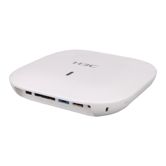
Appendix B Ports WA5320 The WA5320 AP provides the following ports: • One console port • Two GE ports • One USB port • One power port Figure5-1 Ports on the AP (1) Power port (2) 10/100/1000 Mbps Ethernet port (GE1/PoE) -
Page 16: Wa5320E
WA5320E The WA5320E AP provides the following ports: • One console port • Two GE ports • One USB port • Four SMA connectors • One power port Figure5-2 Ports on the AP (1) Power port (2) 10/100/1000 Mbps Ethernet port (GE1/PoE) (3) 10/100/1000 Mbps Ethernet port (GE2/PoE) (4) Console port (5) USB port... - Page 17 Standards and Port Description protocols • GE2/PoE) power from the uplink device. IEEE802.3af In fit AP mode, ports GE1/PoE and GE2/PoE are named GE1/0/1 and GE1/0/2 in MAP files and gigabitethernet 1 and gigabitethernet 2 on the AC, respectively. USB port USB 2.0 Used for transferring data or supplying power.
-
Page 18: Appendix C Leds
Alternating between green and Both the 2.4G and 5G radios have associated clients. blue at 1 Hz Table6-2 LED descriptions (cloud mode, supported only by the WA5320 AP) Status Description No power is present or the LED has been disabled.
Need help?
Do you have a question about the WA5320 and is the answer not in the manual?
Questions and answers