
Related Manuals for Miller 16 CB PLUS CiNX 3


Summary of Contents for Miller 16 CB PLUS CiNX 3
- Page 1 Fluid Head OPERATOR’S MANUAL 1103 CiNX 3 Fluid Head 1105 CiNX 5 Fluid Head 1107 CiNX 7 Fluid Head...
-
Page 2: Table Of Contents
Contents Features and Controls.................................... Introduction......................................Safety Instructions....................................Operating Instructions 1. Attaching Mounting Base................................2. Camera Set-up....................................3. Camera Plate Lock Adjustment..............................4. Counterbalance Control.................................. 5. Pan-Tilt Drag Control..................................6. Pan-Tilt Lock Control..................................7. Illumination...................................... Maintenance......................................Battery Replacement....................................Specifications......................................13-14 Storage........................................Spare Parts and Accessories................................. Warranty......................................... -
Page 3: Features And Controls
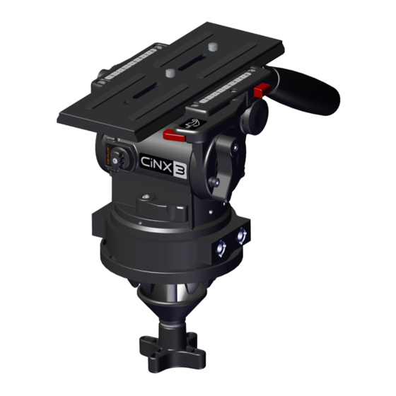
Features and Controls Camera Screws Camera Plate Pan Handle Side Load Lock Lever Tilt Lock Counterbalance Pan Handle Clamp Pan Lock Selector Pan Drag Control Illumination Button Bubble Level Tilt Drag Control CB Plus Selector Knob Tripod Bowl Threaded Stud Clamp Nut Fig. -
Page 4: Introduction
The CiNX Fluid head will give best performance when used on • Ensure PAN HANDLE CLAMP and CLAMP NUT is securely a wide range of Miller tripods (including the 100mm bowl Solo, tightened. 100mm Sprinter, HD and HDC range of Miller tripods). This will •... -
Page 5: Operating Instructions
Fig. 4 Operating Instructions 1. Attaching Mounting Base D150 Claw Ball D100 Claw Ball Fig. 4 3/8” Thread Mitchell Base Adapter Fig. 3 Fig. 5 The CiNX Fluid head comes standard with a D100mm Claw Ball Both D150mm Claw Ball and Mitchell Adaptor can be attached Adaptor which is attached using 3 off M5 x 12mm Socket Cap using 4 off 3/8” x 1” countersunk screws (PN10456) (fig. 5). -
Page 6: Camera Set-Up
Operating Instructions 2. Camera Set-up Camera Plate 2.1 Remove the CAMERA PLATE by pulling and holding the SAFETY RELEASE PIN then pulling the SIDE LOAD LOCK LEVER outwards. Press the SAFETY LATCH BUTTON and remove the CAMERA PLATE from the BASE PLATE (Fig. - Page 7 Operating Instructions 2.4 Align the edge of the CAMERA PLATE with the PLATFORM, and then side load the CAMERA PLATE into the PLATFORM. Once the CAMERA PLATE is in position an audible sound will be heard. At this point, the CAMERA PLATE can slide forward / backward C of G only.
-
Page 8: Camera Plate Lock Adjustment
Operating Instructions 3. Camera Plate Lock Adjustment 3.1 The Camera Plate Lock is designed to secure the CAMERA PLATE in a set position. The CiNX PLATFORM can accept a third party (Arri type) CAMERA PLATE, Locking Screw Adjusting Screw however, the Camera Plate Lock may need to be 3mm Hex Key adjusted to account for small dimensional variations in third party CAMERA PLATES that can significantly... - Page 9 Operating Instructions Turn adjustment screw Turn adjustment screw counterclockwise to clockwise to compensate compensate for a wider for a narrower camera camera plate. plate. Platform Platform Correct position of Side Load Lock Lever at the start of locking action. Platform Fig.
-
Page 10: Counterbalance Control
Operating Instructions 4. Counterbalance Control The counterbalance system was designed to neutralise the effect of the camera weight when it is tilted. The CiNX Fluid head offers a 16 position counterbalance system which is operated with the CB SELECTOR KNOB and the CB PLUS SELECTOR KNOB. -
Page 11: Pan-Tilt Drag Control
Operating Instructions 5. Pan-tilt Drag Control Illumination Button Counter Balance Selector The CiNX 5 & 7 Fluid head offers 7 selectable positions of fluid drag + zero setting in the Pan and Tilt. The settings are equally stepped from light drag in position 1 up to heavy drag in position 7, the drag plates are completely disengaged in position zero. -
Page 12: Maintenance
Maintenance The CiNX Fluid head offers high quality surface coatings, dust and moisture seals. Miller recommends keeping the Fluid head Illumination Button clean at all times by using soft brushes and lint free cloth to wipe over the surfaces. • Do not immerse the Fluid head in any liquid. -
Page 13: Specifications
Supplied with Miller #1065 type). Supplied with Miller #1065 type). Supplied with Miller #1065 When used with Miller #1065 sliding range is When used with Miller #1065 sliding range is When used with Miller #1065 sliding range is Sliding range 150mm (5.9”) - Page 14 Specifications 1103 CiNX 3 1105 CiNX 5 Counterbalance Performance Counterbalance Performance Payload Range 1-19kg (2.2-41.8lbs) Payload Range 2-21kg (4.4-46.2lbs) 1107 CiNX 7 Counterbalance Performance Payload Range 6-25kg (13.2-55.1lbs)
-
Page 15: Storage
Please refer to warranty card for complete details. Miller Authorised Service Agents must carry out all service and repair work. Failure to observe this requirement may void war- ranty. It is advisable to notify Miller or a Miller Authorised. Service... - Page 16 MILLER CAMERA SUPPORT EQUIPMENT 30 Hotham Parade Artarmon, Sydney NSW 2064 Australia Tel: +61 2 9439 6377 Fax: +61 2 9438 2819 Email: sales@miller.com.au D13800-1...
Need help?
Do you have a question about the 16 CB PLUS CiNX 3 and is the answer not in the manual?
Questions and answers