Advertisement
Advertisement
Table of Contents

Summary of Contents for Miller CiNX 8 16 CB PLUS
- Page 1 Fluid Head OPERATOR’S MANUAL #1057 CiNX 8 Fluid Head...
-
Page 2: Features And Controls
Features and Controls Camera Plate (Arri Type) Side Latch Lever Pan Handle Clamp Side Load Lock Lever Pan Handle Safety Release Pin Safety Tilt Lock Knob Pan Lock CB PLUS Selector Knob Front Box Mounting Fig. 1 Fig. 2... - Page 3 Features and Controls 3/8” Camera Screws Side Load Lock Lever Tilt Lock Counterbalance Selector Accessory Mounting Pan Drag Control Illumination button Bubble Level Tilt Drag Control Fig. 3...
-
Page 4: Safety Instructions
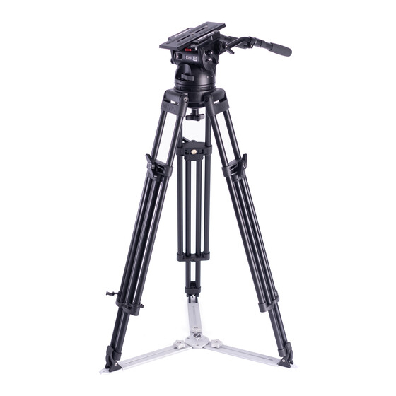
Hold camera securely whilst adjusting the CLAMP NUT to The CinX 8 will give best performance when used on a Miller level the Fluid Head. Ø150 HD Tripod or the Miller HD Mitchell Base Tripod. This will ensure maximum system stability to suit any professional set-up. - Page 5 Operating Instructions 1. Attaching Mount Base Mitchell Base Adapter (1225) (Fig. 4) are available as an optional accessory. Mitchell Base Adapter can be attached using 4 off 3/8” x 1” countersunk screws (PN10456) (fig. 4). This allows you to mount the CINX 8 to any Mitchell base tripod, pedestal etc. or to any Ø150mm bowl tripod.
-
Page 6: Camera Setup
Operating Instructions Camera Plate (Arri Type) 2. Camera Set-up 2.1 Engage SAFETY TILT LOCK KNOB to lock tilt movement in the vertical plane. Side Latch Lever Remove the CAMERA PLATE by pressing and holding the SAFETY RELEASE PIN then pulling the SIDE LOAD LOCK LEVER outwards. - Page 7 Operating Instructions 2.4 Align the edge of the CAMERA PLATE with the BASE PLATE, and then side load the CAMERA PLATE into the BASE PLATE. Once the CAMERA PLATE is in position an C of G audible sound will be heard. At this point, the CAMERA PLATE can slide forward / backward only.
- Page 8 Operating Instructions 3mm Socket Lock Screw 3. Camera Plate Lock Adjustment (Use a 3mm Hex Key) The Camera Plate Lock is designed to secure the Adjusting Nut CAMERA PLATE in a set position. The CinX 8 BASE PLATE can accept a third party (Arri type) CAMERA PLATE, however, the Camera Plate Lock may need to be adjusted to account for small dimensional variations in third party CAMERA PLATES that can significantly affect...
- Page 9 Operating Instructions 3.4 Using a 3 mm Hex key unlock the LOCK SOCKET SCREW Turn adjustment screw (fig. 7), then using a broad flat screw driver turn the counterclockwise to ADJUSTING NUT (fig. 7) in the direction shown by 1/8 compensate for a wider of a turn and re-check step 3.2, repeat 3.4 if necessary.
- Page 10 Operating Instructions 4. Counterbalance Control The counterbalance system was designed to neutralise the effect of the camera weight when it is tilted. The CiNX 8 Fluid head offers a 16 position counterbalance system which is operated CB Plus Selector Knob - Front View CB Selector Knob - Back View with the CB SELECTOR KNOB and the CB PLUS SELECTOR KNOB.
- Page 11 Operating Instructions 5. Pan / Tilt Drag Control Illumination Button Counterbalance Selector The CinX 8 Fluid Head offers 7 selectable positions of fluid drag + zero setting in the Pan and Tilt. The settings are equally stepped from light drag in position 1 up to heavy drag in position 7, the drag plates are completely disengaged in position zero.
-
Page 12: Maintenance
Maintenance The CinX 8 Fluid Head offers high quality surface coatings. Miller recommends keeping the Fluid Head clean at all times by using Illumination Button soft brushes and lint free cloth to wipe over the surfaces. • Do not immerse the Fluid Head in any liquid. -
Page 13: Specifications
Specifications COUNTERBALANCE PERFORMANCE CiNX 8 Weight 5.7 kg (12.6 lbs) Payload Range 4.5 – 40 kg (9.9 – 88.2 lbs) (COG @ 125mm) Pan-Tilt Drag 7 Selectable fluid drag positions + 0 Pan-Tilt Lock Positive lock caliper brake system plus Safety Tilt Lock. - Page 14 Specifications Fig. 13...
-
Page 15: Spare Parts And Accessories
Storage Service, Sales and Support The CinX 9 Fluid Head can be stored for extended periods; Miller Miller Authorised Service Agents must carry out all service recommends storage in a Miller Soft Case and the following: and repair work. Failure to observe this requirement may void warranty. - Page 16 MILLER CAMERA SUPPORT EQUIPMENT 6 Ross Place Wetherill Park 2164 NSW Sydney, Australia Tel: +61 2 9439 6377 Email: sales.au@millertripods.com D13062-1...


Need help?
Do you have a question about the CiNX 8 16 CB PLUS and is the answer not in the manual?
Questions and answers