Table of Contents
Advertisement
Quick Links
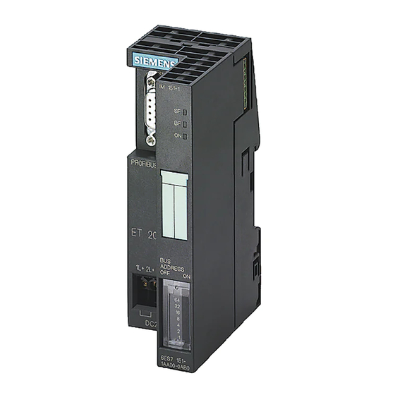
SIMATIC ET 200S distributed I/O IM151-1 HIGH FEATURE interface module (6ES7151-1BA02-0AB0)
SIMATIC
ET 200S distributed I/O
IM151-1 HIGH FEATURE interface
module (6ES7151-1BA02-0AB0)
Manual
The following supplement is part of this documentation:
No.
Product Information
1
LED display of the configuration
and parameter assignment errors
03/2008
A5E01075975-02
Drawing number
Edition
A5E02478858-01
03/2009
Preface
______________
Properties
______________
Parameters
______________
Functions
Interrupt, error, and system
______________
messages
______________
Response times
1
2
3
4
5
Advertisement
Table of Contents


Need help?
Do you have a question about the SIMATIC IM151-1 and is the answer not in the manual?
Questions and answers