Simrad ES120-7C Installation Manual
Split-beam transducer
Hide thumbs
Also See for ES120-7C:
- Datasheet (2 pages) ,
- Installation manual (70 pages) ,
- Manual (1 page)

Related Manuals for Simrad ES120-7C


Summary of Contents for Simrad ES120-7C
- Page 1 Installation Manual Simrad ES120-7C Split-beam transducer TECHNOLOGY FOR SUSTAINABLE FISHERIES www.simrad.com...
- Page 3 The installation shipyard must provide all necessary installation drawings. If required, all documents provided by the shipyard for the physical installation of the ES120-7C must be approved by the vessel’s national registry and corresponding maritime authority and/or classification society. The shipowner and shipyard doing the installation are responsible for obtaining and paying for such approval.
- Page 4 If you require maintenance or repair, contact your local dealer. You can also contact us using the following address: simrad.support@simrad.com. If you need information about our other products, visit https: //www.simrad.com. On this website you will also find a list of our dealers and distributors. Kongsberg Maritime AS www.kongsberg.com...
-
Page 5: Table Of Contents
Connecting the transducer cable to the transceiver............... 42 Painting the transducer face ....................43 CABLE LAYOUT AND INTERCONNECTIONS......... 45 ES120-7C Connecting to a 12-pin Amphenol socket ............46 12-pin Amphenol plug ......................49 ES120–7C with MacArtney SubConn connector ..............50 TRANSDUCER INSTALLATION PRINCIPLES........ - Page 6 Summary and general recommendations ................75 DRAWING FILE................77 About the drawings in the drawing file................. 78 204579 Dimensions ES120-7C with open ended cable............79 428878 Dimensions ES120–7C Subconn ................81 204675 Mounting ring ES120-7C..................83 204677 Clamping ring ES120–7C ..................85 599-035130 Bushing ES120-7C ...................
-
Page 7: About This Manual
The outline dimensions of the ES120-7C transducer and the relevant installation items can be found in the Drawing file chapter in this manual. - Page 8 Simrad ES120-7C Installation Manual End user manuals and source drawings (normally in AutoCad format) can be downloaded from our website. • https://www.simrad.com Registered trademarks Observe the registered trademarks that apply. Windows ® is a registered trademark of Microsoft Corporation in the United States and other countries.
-
Page 9: Simrad Es120-7C
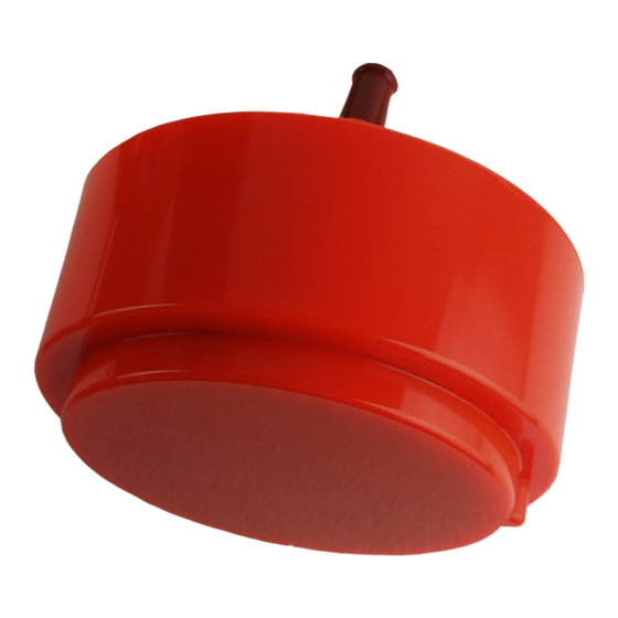
Simrad ES120-7C Simrad ES120-7C The Simrad ES120-7C is a split beam composite transducer designed for fishery and underwater science applications. The beamwidth is 7 degrees at its nominal operational frequency. The transducer offers a large bandwidth. This provides a fine range resolution, which is important for single fish detection and target strength measurements. -
Page 10: Order Information
Simrad ES120-7C Installation Manual Order information To order the ES120-7C, or any of the optional items provided with it, contact your local dealer. If you do not have a regular dealer, a list of all our distributors and dealers can be found on our website. -
Page 11: Physical And Environmental Specifications
These optional items are available for the installation. The items can be manufactured locally, or ordered from Kongsberg Maritime. The items are not included with the ES120-7C delivery, and must be ordered separately. The order number for the cable is included in case the original cable fitted to the transducer is too short. -
Page 12: Support Information
204678 Mounting arrangement ES120-7C, page 88 Support information If you need technical support for your Simrad ES120-7C you must contact your local dealer, or one of our support departments. A list of all our offices and dealers is provided on our website. - Page 13 Telefax • http://www.simrad.fr Website • simrad.france@simrad.com E-mail address • : Kongsberg Underwater Technology Inc / Simrad Fisheries Company name • : 19210 33rd Ave W, Suite B, Lynnwood, WA 98036, USA Address • : +1 425 712 1136 Telephone •...
- Page 14 Simrad ES120-7C Installation Manual Korea • : Kongsberg Maritime Korea Ltd Company name • : #1101-Harbor Tower, 113-1, Nampodong 6-Ga, Jung-Gu, Busan 600-046 Korea Address • : +82-51-242-9933 Telephone • : +82-51-242-9934 Telefax • https://www.simrad.com Website • simrad.korea@simrad.com E-mail address China •...
-
Page 15: Transducer Handling And Maintenance
Transducer handling and maintenance Transducer handling and maintenance Topics Rules for transducer handling, page 14 Approved anti-fouling paints, page 15 Inspecting and cleaning the transducer face, page 16 Painting the transducer face, page 18 330254/B... -
Page 16: Rules For Transducer Handling
Cleaning and painting the transducer face During normal use, the transducer is subjected to biological fouling. If this marine growth is excessive, it will reduce the performance of the ES120-7C. The transducer has not been designed with any protection against biological fouling. -
Page 17: Approved Anti-Fouling Paints
Because some paint types may be aggressive to the polyurethane in the transducer, consult our list of approved paints. The list can also be found on http://www.simrad.com. Observe the relevant instructions and safety information provided by the paint manufacturer. -
Page 18: Inspecting And Cleaning The Transducer Face
Painting the transducer face, page 18 Inspecting and cleaning the transducer face Marine growth (biological fouling) on the transducer face reduces the ES120-7C performance. For this reason, it is important to keep the transducer face clean. Every time your vessel is in dry dock, you must remove the marine growth. At the same time, you must inspect the transducer closely for physical damage. - Page 19 During normal use, the transducer is subjected to biological fouling. If this marine growth is excessive, it will reduce the performance of the ES120-7C. Whenever opportunity arise, typically when the vessel is dry-docked, the transducer face must be cleaned for shells and other marine growth.
-
Page 20: Painting The Transducer Face
Do a thorough visual inspection of the transducer. Check for dents, scratches, holes or other damage to the surface. If you suspect damage, take a high resolution photo. Contact your dealer or the Simrad support organization for advice. If necessary, apply anti-fouling paint as described in the dedicated procedure. - Page 21 Abrade the transducer surface using a sanding paper with 240 inch grit size. Do not exceed a surface roughness (R ) of 35 microns as this can influence the ES120-7C performance. Remove all dust. Apply the primer, and let it dry.
- Page 22 Simrad ES120-7C Installation Manual Related topics Transducer handling and maintenance, page 13 Approved anti-fouling paints, page 15 Inspecting and cleaning the transducer face, page 16 Installing the transducer, page 21 330254/B...
-
Page 23: Installing The Transducer
Installing the transducer Installing the transducer Topics Installation summary, page 22 Designing, manufacturing and mounting the installation hardware, page 24 Installing the cable gland, page 25 Designing, manufacturing and mounting the steel conduit, page 27 Unpacking the transducer from its transport crate, page 29 Installing the transducer cable, page 30 Mounting the transducer, page 33 Using self-locking taps, page 35... -
Page 24: Installation Summary
Simrad ES120-7C Installation Manual Installation summary The installation of the ES120-7C transducer is a key task for successful installation of the echo sounder system. Not only will you need to penetrate the vessel’s hull, you must also to select a physical location for maximum performance and minimum acoustic and electric noise. - Page 25 Installing the transducer Procedure Determine the physical location of the transducer. The decision must be based on: • The vessel drawings • The shape and properties of the hull Make sure that all possible considerations are made to reduce noise. •...
-
Page 26: Designing, Manufacturing And Mounting The Installation Hardware
The outline dimensions of the ES120-7C transducer and the relevant installation items can be found in the Drawing file chapter in this manual. Relevant outline dimensions and production drawings can be download from our website. -
Page 27: Installing The Cable Gland
Transducer installation principles, page 51 Where to install the transducer, page 70 Drawing file, page 77 204579 Dimensions ES120-7C with open ended cable, page 79 204675 Mounting ring ES120-7C, page 83 204677 Clamping ring ES120–7C, page 85 204678 Mounting arrangement ES120-7C, page 88... - Page 28 Simrad ES120-7C Installation Manual Context These items are all provided as a part of the transducer delivery. Bushing, penetrates the hull plating Washer Rubber gasket Packing nipple Procedure Depending on the chosen installation method (blister or tank), make a hole for the bushing.
-
Page 29: Designing, Manufacturing And Mounting The Steel Conduit
Installing the transducer Designing, manufacturing and mounting the steel conduit A steel conduit is used to protect the transducer cable. The conduit serves two purposes. It will protect the cable, and shield it from electric noise. Depending on how the steel conduit is terminated over the transducer, it may also secure the watertight integrity of the vessel. - Page 30 If a cable is damaged, and penetrated by water, the transducer may be damaged beyond repair. The outline dimensions of the ES120-7C transducer and the relevant installation items can be found in the Drawing file chapter in this manual. End user manuals and source drawings (normally in AutoCad format) can be downloaded from our website.
-
Page 31: Unpacking The Transducer From Its Transport Crate
Installing the transducer The steel conduit must preferably be straight. Start the conduit immediately above the transducer, and terminate it well above the water line. If you must introduce bends on the steel conduit, take the minimum cable bending radius into consideration. Manufacture the steel conduit according to the relevant production standards. -
Page 32: Installing The Transducer Cable
Simrad ES120-7C Installation Manual • Do not lift the transducer by the cable. • Do not step on the transducer cable. • Do not damage the transducer cable, and avoid exposure to sharp objects. Procedure Place a protective mat on the cart to safeguard the transducer face. - Page 33 Installing the transducer You must be equipped with a standard set of tools. This tool set must comprise the normal tools for electronic and electromechanical tasks. This includes different screwdriver types, pliers, spanners, a cable stripper, a soldering iron, etc. We recommend that all tools are demagnetized to protect your equipment.
- Page 34 Simrad ES120-7C Installation Manual Lower the fish tape (wire pulling tool) down from the top of the steel conduit, and through the bushing. Make sure that the rubber gasket, washers and packing nipple are threaded onto the transducer cable. These items are kept between the bushing and the transducer.
-
Page 35: Mounting The Transducer
Installing the transducer Mounting the transducer When all the preparations have been made, observe this procedure for the mounting of the transducer If required, additional and more detailed procedures must be provided by the installation ship yard. Prerequisites The following requirements must be met before mounting the transducer: •... - Page 36 Simrad ES120-7C Installation Manual Mounting ring Cable service loop Transducer Clamping ring Bolt Context Observe the physical size and weight of the transducer. Unless a suitable lifting device is available, make sure that enough manpower is available to lift, hold and fasten the transducer.
-
Page 37: Using Self-Locking Taps
Installing the transducer Related topics Installing the transducer, page 21 Using self-locking taps, page 35 204579 Dimensions ES120-7C with open ended cable, page 79 204675 Mounting ring ES120-7C, page 83 204677 Clamping ring ES120–7C, page 85 204678 Mounting arrangement ES120-7C, page 88... - Page 38 Simrad ES120-7C Installation Manual Emuge’s saw-tooth profile up to pitch P ≤ 0.7 mm Emuge’s saw-tooth profile up to pitch P >0.7 mm Standard thread External thread Internal thread The advantages of using Emuge self-lock thread include: • The thread locking feature if integrated in the internal thread •...
- Page 39 The illustrations and information is for reference only. The drawing is provided with the following text or similar text: Note Drill diameters for threads differ from standard. Self-lock taps can be supplied by Simrad. Taps The pretension locking thread self-lock (taps) from manufacturer Emuge must be used.
- Page 40 Use Emuge self-lock gauges. Note that the gauge must be used in the correct direction. Self-lock taps provided by Simrad The following self-lock taps are on stock at Simrad, and can be ordered from us: Threads Drill diameter for threads Part no.
-
Page 41: Splicing The Transducer Cable
Do not solder the wires together with only electrical tape for insulation. This will result in electrical noise and reduced operational performance. Related topics Connecting the transducer cable to the transceiver, page 42 12-pin Amphenol plug , page 49 ES120-7C Connecting to a 12-pin Amphenol socket, page 46 330254/B... -
Page 42: Splicing The Cable Using A Grounded Junction Box
The screen of the transducer cables must not have electrical connection to the junction box housing or cable gland, insulate if necessary. Related topics ES120-7C Connecting to a 12-pin Amphenol socket, page 46 12-pin Amphenol plug , page 49 Splicing the cable using a junction box isolated from vessel’s... - Page 43 Verify that you have connected the wires 1:1, and that the colours match. Connect the cable screens to the cable glands in the junction box. Related topics Installing the transducer, page 21 ES120-7C Connecting to a 12-pin Amphenol socket, page 46 12-pin Amphenol plug , page 49 330254/B...
-
Page 44: Connecting The Transducer Cable To The Transceiver
Each tool must be provided in various sizes. We recommend that all tools are demagnetized to protect your equipment. Context The ES120-7C transducer can be used with a variety of echo sounder transceivers. These use different plugs and connectors. Procedure Make sure that an ample length of the transducer cable is available for maintenance and replacement. -
Page 45: Painting The Transducer Face
Installing the transducer Painting the transducer face Marine growth (biological fouling) on the transducer face reduces the ES120-7C performance. We recommend that you paint the transducer face immediately after installation, and then again as often as required to maintain the protection. - Page 46 Simrad ES120-7C Installation Manual Abrade the transducer surface using a sanding paper with 240 inch grit size. Do not exceed a surface roughness (R ) of 35 microns as this can influence the ES120-7C performance. Remove all dust. Apply the primer, and let it dry.
-
Page 47: Cable Layout And Interconnections
Cable layout and interconnections Cable layout and interconnections Topics ES120-7C Connecting to a 12-pin Amphenol socket, page 46 12-pin Amphenol plug , page 49 ES120–7C with MacArtney SubConn connector, page 50 330254/B... -
Page 48: Es120-7C Connecting To A 12-Pin Amphenol Socket
Simrad ES120-7C Installation Manual ES120-7C Connecting to a 12-pin Amphenol socket The Simrad ES120-7C is a split beam composite transducer designed for fishery and underwater science applications. The transducer shall be connected to terminals through on a circular 12-pin Amphenol socket (Type 97-12-19S). This socket is used on the General Purpose Transceiver (GPT), and on several versions of the Wide Band Transceiver (WBT). - Page 49 Cable layout and interconnections Yellow Black Blue Black Digital output Digital ground Black Cable screen Screen The cable has four pairs of white and black conductors. The different sectors are defined by small numbers marked in white on the each black conductors. These are numbered 1–4 which indicate the sectors of transducer.
- Page 50 Simrad ES120-7C Installation Manual The cable screen must be connected to the housing on the transducer plug. Note The black wires in the transducer cable are not for grounding. You must never connect these together, and you must not connect any of them to vessel ground.
-
Page 51: 12-Pin Amphenol Plug
Installing the transducer cable, page 30 Connecting the transducer cable to the transceiver, page 42 ES120-7C Connecting to a 12-pin Amphenol socket, page 46 Splicing the cable using a grounded junction box, page 40 Splicing the cable using a junction box isolated from vessel’s ground, page 40... -
Page 52: Es120-7C With Macartney Subconn Connector
Simrad ES120-7C Installation Manual ES120–7C with MacArtney SubConn connector The 8-pin male connector used on the transducer cable is manufactured by MacArtney as a part of their "SubConn Micro Circular" series. Its type identification is MCIL8M. Pin configuration Signal name... -
Page 53: Transducer Installation Principles
Transducer installation principles Transducer installation principles Topics Transducer installation in a blister, page 52 Transducer installation using an arctic tank with acoustic window, page 55 Transducer installation in keel box, page 57 Transducer installation using drop keel, page 58 About cable glands, page 61 Using a steel conduit to protect the transducer cable, page 65 Smooth surface is important, page 68 Using a suitable inclination angle, page 68... -
Page 54: Transducer Installation In A Blister
Simrad ES120-7C Installation Manual Transducer installation in a blister In order to install a transducer with a circular housing, one recommended installation method is by means of a blister. The blister must be designed and manufactured by the installation shipyard to fit the transducer, as well as the vessel’s size and hull shape. The transducer may be added to an already existing blister that also holds other flush mounted transducers. - Page 55 Transducer installation principles Example Streamlined blister Stiffening rib Drainage holes Inclination angle(1 °) Mounting ring Clamping ring Air outlet Cable service loop Bushing Height: 400 mm (Minimum) Rounded corners (Recommended around 50mm) Physical location of the blister The blister is placed on the side of the hull. The distance from the keel is a trade off between a close distance giving a turbulent flow of water in a narrow passage, and a large distance bringing the transducer higher up, and therefore more affected by the vessel roll.
- Page 56 Simrad ES120-7C Installation Manual Keel Transducer blister Horizontal distance between the keel and the blister Vertical distance between the bottom of the keel and the blister surface Observe the horizontal and vertical distances between the keel and the transducer blister. (C + D)
-
Page 57: Transducer Installation Using An Arctic Tank With Acoustic Window
Transducer installation principles Note Obstructions on these surfaces will create problems with turbulent flow, and may cause noise. Related topics Using a steel conduit to protect the transducer cable, page 65 Smooth surface is important, page 68 Using a suitable inclination angle, page 68 Transducer installation using an arctic tank with acoustic window Vessels operating in arctic waters need special attention on transducer installation. - Page 58 Simrad ES120-7C Installation Manual Bushing Steel pipe(minimum1.5m above waterline) 11/4" Plug BSP Charge line , 20% propylene glycol and clean water above double bottom with easy access Air vent screw Liquid filled (20% propylene glycol and clean water) Trunk Transducer...
-
Page 59: Transducer Installation In Keel Box
Transducer installation principles Mounting screws or bolts must not be extruding from the transducer or the plating immediately around it. Note Obstructions on these surfaces will create problems with turbulent flow, and may cause noise. Related topics Using a steel conduit to protect the transducer cable, page 65 Smooth surface is important, page 68 Using a suitable inclination angle, page 68 Transducer installation in keel box... -
Page 60: Transducer Installation Using Drop Keel
Using a suitable inclination angle, page 68 Transducer installation using drop keel If your vessel is fitted with a drop keel, this is a superior platform for the ES120-7C transducer. Drop keels are often used on larger research vessels. A drop keel will frequently protrude as far as three meters below the hull. - Page 61 The drawing (normally in AutoCad format) can be downloaded from our website. • https://www.simrad.com Smooth surface is important Make sure that the surface of the transducer face, as well as the plating and putty around the transducer is as even and smooth as possible.Obstructions on these surfaces will create...
- Page 62 Simrad ES120-7C Installation Manual Mounting screws or bolts must not be extruding from the transducer or the plating immediately around it. Note Obstructions on these surfaces will create problems with turbulent flow, and may cause noise. Related topics Using a steel conduit to protect the transducer cable, page 65...
-
Page 63: About Cable Glands
Note Simrad strongly recommends that a length of conduit is fitted around transducer cable glands made of steel or bronze and extended over the water-line inside the vessel. This precaution reduces the danger of flooding in the event of gland failure and transducers installed in this manner are also easier to replace. -
Page 64: Cable Gland For Wooden And Grp Hulls
A bronze cable gland kit can be made for wooden and GRP vessels. Note Simrad takes no responsibility for the correct manufacturing, installation of cable glands, associated hull modifications and/or structural support of transducer cable penetration. These activities are subject to individual approval by the respective classification society for the vessel in question. - Page 65 Transducer installation principles Packing nipple Washers Rubber gaskets Steel conduit Cable to echo sounder (or a junction box) Note Make sure that you do not damage the transducer cable by tightening the packing nipple too hard. Related topics Installing the transducer, page 21 330254/B...
-
Page 66: Cable Glands For Small Hulls
Simrad ES120-7C Installation Manual Cable glands for small hulls For smaller vessels that need not be classified, cable gland can be made as illustrated: Packing nipple Rubber gaskets Plastic disc Rubber gaskets Bushing Backing nut Backing washer O-ring O-ring Cable to echo sounder (or a junction box) -
Page 67: Order Numbers For Cable Gland Kits
Start the conduit immediately above the transducer, and terminate it well above the water line. It is strongly recommended to lay a steel conduit from the cable gland above the transducer to the ES120-7C transceiver, and to pull the transducer cable through this conduit. The 330254/B... - Page 68 Simrad ES120-7C Installation Manual conduit serves two purposes. It will protect the cable, and shield it from electric noise. Depending on how the steel conduit is terminated over the transducer, it may also secure the watertight integrity of the vessel.
- Page 69 Transducer installation principles Related topics Installing the transducer, page 21 Transducer installation in a blister, page 52 Transducer installation using an arctic tank with acoustic window, page 55 Transducer installation in keel box, page 57 Transducer installation using drop keel, page 58 330254/B...
-
Page 70: Smooth Surface Is Important
Simrad ES120-7C Installation Manual Smooth surface is important Make sure that the surface of the transducer face, as well as the plating and putty around the transducer is as even and smooth as possible. Obstructions on these surfaces will create problems with turbulent flow, and may cause noise. - Page 71 Transducer installation principles Note Ensure that you do not mount the transducer with a negative inclination angle. This may cause turbulence on the transducer face, and reduced ES120-7C performance. Related topics Transducer installation in a blister, page 52 Transducer installation using an arctic tank with acoustic window, page 55...
-
Page 72: Where To Install The Transducer
Simrad ES120-7C Installation Manual Where to install the transducer Topics Introduction to transducer location, page 71 Mount the transducer deep, page 71 Avoid protruding objects near the transducer, page 72 Mount the transducer at forward part of hull to minimize the effects from the flow boundary... -
Page 73: Introduction To Transducer Location
Mount the transducer deep In order to achieve the best possible ES120-7C performance, mount the transducer as deep as possible under the vessel’s hull. There are several reasons for this recommendation. -
Page 74: Avoid Protruding Objects Near The Transducer
Simrad ES120-7C Installation Manual Slamming Slamming happens if the vessel hull climbs out of the water in heavy seas. The force of the water when the hull falls down may push the transducer up, and may cause damage both to the transducer and to its mounting. This is especially important for low frequency transducers with large faces. -
Page 75: Keep The Transducer Far Away From The Propellers
The propulsion propellers is the dominant noise source on most vessels. The noise is easily transmitted through the water. This noise may often reduce the overall performance of your ES120-7C. The transducer must be installed as far away from the propellers as possible. The best positions are therefore on the fore part of the hull. -
Page 76: Mount The Transducer At A Safe Distance From Bow Thruster(S)
When in operation, the noise and cavitation bubbles created by the thruster may make your ES120-7C Transducer useless, almost no matter where the transducer is installed. When the bow thrusters are not in operation, the tunnel creates turbulence. If your vessel is pitching, the tunnel may be filled with air or aerated water in the upper position and release this in the lower position. -
Page 77: Summary And General Recommendations
Where to install the transducer Summary and general recommendations Some of the installation guidelines provided for transducer location may be conflicting. For this reason, each vessel must be treated individually in order to find the best compromise. In general, the most important factor is to avoid air bubbles in front of the transducer face. For this reason, the recommended transducer location is normally in the fore part of the hull, well ahead of the noise created by the bow wave. - Page 78 Simrad ES120-7C Installation Manual If the vessel hull has a bulbous bow, this may well be a good transducer location, but also in this case the flow pattern of the aerated water must be taken into consideration. The foremost part of the bulb is often a good location.
-
Page 79: Drawing File
Drawing file Drawing file Topics About the drawings in the drawing file, page 78 204579 Dimensions ES120-7C with open ended cable, page 79 428878 Dimensions ES120–7C Subconn, page 81 204675 Mounting ring ES120-7C, page 83 204677 Clamping ring ES120–7C, page 85... -
Page 80: About The Drawings In The Drawing File
Simrad ES120-7C Installation Manual About the drawings in the drawing file Relevant drawings related to the installation and/or maintenance of the ES120-7C are provided for information purposes only. Note These drawings are provided only for information and planning purposes. Information may be omitted. -
Page 81: 204579 Dimensions Es120-7C With Open Ended Cable
Drawing file 204579 Dimensions ES120-7C with open ended cable Download the source drawing from the transducer pages on https://www.simrad.com/td. 330254/B... - Page 82 Simrad ES120-7C Installation Manual Related topics Physical and environmental specifications, page 9 Mounting the transducer, page 33 Designing, manufacturing and mounting the installation hardware, page 24 330254/B...
-
Page 83: 428878 Dimensions Es120-7C Subconn
Drawing file 428878 Dimensions ES120–7C Subconn Download the source drawing from the transducer pages on https://www.simrad.com/td. 330254/B... - Page 84 Simrad ES120-7C Installation Manual 330254/B...
-
Page 85: 204675 Mounting Ring Es120-7C
Drawing file 204675 Mounting ring ES120-7C Download the source drawing from the transducer pages on https://www.simrad.com/td. 330254/B... - Page 86 Simrad ES120-7C Installation Manual Related topics Physical and environmental specifications, page 9 Mounting the transducer, page 33 Designing, manufacturing and mounting the installation hardware, page 24 330254/B...
-
Page 87: 204677 Clamping Ring Es120-7C
Drawing file 204677 Clamping ring ES120–7C Download the source drawing from the transducer pages on https://www.simrad.com/td. 330254/B... - Page 88 Simrad ES120-7C Installation Manual Related topics Physical and environmental specifications, page 9 Mounting the transducer, page 33 Designing, manufacturing and mounting the installation hardware, page 24 330254/B...
-
Page 89: 599-035130 Bushing Es120-7C
Drawing file 599-035130 Bushing ES120-7C Download the source drawing from the transducer pages on https://www.simrad.com/td. 330254/B... -
Page 90: 204678 Mounting Arrangement Es120-7C
Simrad ES120-7C Installation Manual 204678 Mounting arrangement ES120-7C Download the source drawing from the transducer pages on https://www.simrad.com/td. 330254/B... - Page 91 Drawing file 330254/B...
- Page 92 Simrad ES120-7C Installation Manual Related topics Physical and environmental specifications, page 9 Mounting the transducer, page 33 Designing, manufacturing and mounting the installation hardware, page 24 330254/B...
- Page 93 ........55 acoustic noise........... 71, 73 amphenol socket transducer ........... 73 ES120-7C transducer connection ......46 circular socket anti-fouling paints ES120-7C transducer connection ......46 approved ............ 15 clamping ring International Marine Coatings ......16 description .........
- Page 94 ........29 about ............78 hull surface ES120-7C .......... 79, 81, 87 protruding objects.......... 72 ES120-7C clamping ring drawing ....... 85 hydrophone ES120-7C mounting ring drawing....... 83 anti-fouling paints ......... 15 physical and environmental specifications ....9 steel conduit ..........
- Page 95 Index anti-fouling paints ......... 16 optional items ..........8 transducer ............. 8 outline dimensions about ............78 ES120-7C ..........79, 81 Jotun physical and environmental specifications ....9 anti-fouling paints ......... 15 overview junction box transducer installation ........22 splicing the transducer cable ......39...
- Page 96 ........ 65 size steel conduit ..........65 ES120-7C ..........79, 81 transducer connection ES120-7C clamping ring drawing ....... 85 ES120-7C ........... 46 ES120-7C mounting ring drawing....... 83 transducer ES120-7C physical and environmental specifications ....9 bushing ............87 slamming description ............
- Page 98 ©2019 Kongsberg Maritime...
Need help?
Do you have a question about the ES120-7C and is the answer not in the manual?
Questions and answers