Table of Contents
Advertisement
Quick Links
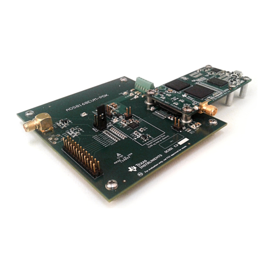
The ADS8168 evaluation module (EVM) performance demonstration kit (PDK) is a platform for evaluating
the performance of the ADS8168 successive approximation register analog-to-digital converter (SAR
ADC). The ADS8168EVM-PDK includes the ADS8168EVM board, the PHI controller board, and
accompanying computer software that enables the user to communicate with the ADC over a universal
serial bus (USB), capture data, and perform data analysis. This user's guide includes complete circuit
descriptions, schematic diagrams, and a bill of materials.
The following related documents are available through the Texas Instruments web site at www.ti.com.
SBAU291 – November 2017
Submit Documentation Feedback
Figure 1. ADS8268EVM-PDK
Related Documentation
Device
ADS8168
REF5050
OPA320
Copyright © 2017, Texas Instruments Incorporated
SBAU291 – November 2017
ADS8168EVM-PDK
Literature Number
SBAS817
SBOS410
SBOS513
User's Guide
1
ADS8168EVM-PDK
Advertisement
Table of Contents

Related Manuals for Texas Instruments ADS8168EVM-PDK


Summary of Contents for Texas Instruments ADS8168EVM-PDK
-
Page 1: Ads8268Evm-Pdk
(USB), capture data, and perform data analysis. This user's guide includes complete circuit descriptions, schematic diagrams, and a bill of materials. Figure 1. ADS8268EVM-PDK The following related documents are available through the Texas Instruments web site at www.ti.com. Related Documentation Device... -
Page 2: Table Of Contents
ADS8168 Device Driver Installation Wizard Prompts ................. LabVIEW Run-Time Engine Installation ..............ADS8168EVM Successful Installation Complete ................. ADS8168 EVM Folder Post-Installation ............ADS8168EVM-PDK Hardware Setup and LED Indicators ................Launch the ADS8168EVM GUI Software ..................EVM GUI Global Input Parameters ...................... Time Domain Display ..................... - Page 3 Trademarks Microsoft, Windows are registered trademarks of Microsoft Corporation. LabVIEW is a trademark of National Instruments. All other trademarks are the property of their respective owners. SBAU291 – November 2017 ADS8168EVM-PDK Submit Documentation Feedback Copyright © 2017, Texas Instruments Incorporated...
-
Page 4: Overview
Overview The ADS8168EVM-PDK is a platform for evaluating the performance of the ADS8168 SAR ADC, which is a 8-channel, 16-bit, 1-MSPS device. The evaluation kit includes the ADS8168EVM board and the precision host interface (PHI) controller board that enables the accompanying computer software to communicate with the ADC over USB for data capture and analysis. -
Page 5: Ads8168Evm Features
Overview www.ti.com Figure 2. ADS8168EVM Features SBAU291 – November 2017 ADS8168EVM-PDK Submit Documentation Feedback Copyright © 2017, Texas Instruments Incorporated... -
Page 6: Evm Analog Interface
AIN7 Analog Channel 7 P2.18 AIN8 Analog Channel 8 P2.20, P2.22, P2.24 Positive analog power supply P2.21, P2.23 Negative analog power supply (default connection is GND) ADS8168EVM-PDK SBAU291 – November 2017 Submit Documentation Feedback Copyright © 2017, Texas Instruments Incorporated... -
Page 7: Ads8168 Internal Reference And Evm Onboard Reference
ADS8168 to AV – 0.3 V. A 5-V reference voltage is possible due to the operation of AV at 5.3 V. Figure 3. REF5050 5.0-V External Reference Source SBAU291 – November 2017 ADS8168EVM-PDK Submit Documentation Feedback Copyright © 2017, Texas Instruments Incorporated... -
Page 8: Digital Interfaces
EVM with which the PHI communicates: the ADS8168 ADC (over single- or dual-SDO SPI bus) and the EEPROM (over I C). The EEPROM comes pre-programmed with the information required to configure and initialize the ADS8168EVM-PDK platform. Once the hardware is initialized, the EEPROM is no longer used. ADS8168 Digital Interface... -
Page 9: Power Supplies
• should be limited to AV – 5.5 V (nominally, 200 mV) to protect the OPA350 circuits onboard. SBAU291 – November 2017 ADS8168EVM-PDK Submit Documentation Feedback Copyright © 2017, Texas Instruments Incorporated... -
Page 10: Ads8168Evm_Pdk Initial Setup
ADS8168EVM_PDK Initial Setup This section explains the initial hardware and software setup procedure that must be completed for the proper operation of the ADS8168EVM-PDK. Default Jumper Settings Jumper JP2 selects the voltage level to be applied to the AIN-COM pin on the ADS8168. The default position is between pins 1-2, applying GND to the AIN-COM. -
Page 11: Evm Graphical User Interface (Gui) Software Installation
Download the latest version of the EVM GUI installer from the Tools and Software folder of the ADS8168EVM-PDK and run the GUI installer to install the EVM GUI software. The user must have administrator privileges on the PC to be able to install the EVM software. The following steps list the... -
Page 12: Software Installation Prompts
ADS8168EVM_PDK Initial Setup www.ti.com Figure 5. Software Installation Prompts ADS8168EVM-PDK SBAU291 – November 2017 Submit Documentation Feedback Copyright © 2017, Texas Instruments Incorporated... -
Page 13: Ads8168 Device Driver Installation Wizard Prompts
NOTE: A notice may appear on the screen stating that Widows cannot verify the publisher of this driver software. Select Install this driver software anyway. Step 3. The ADS8168EVM-PDK requires LabVIEW™ Run-Time Engine may prompt for the installation of this software, if not already installed. -
Page 14: Ads8168Evm Successful Installation Complete
ADS8168EVM_PDK Initial Setup www.ti.com Figure 8. ADS8168EVM Successful Installation Complete Step 4. After these installations, verify that C:\Program Files (x86)\Texas Instruments\ADS8168 EVM is as shown in Figure Figure 9. ADS8168 EVM Folder Post-Installation ADS8168EVM-PDK SBAU291 – November 2017 Submit Documentation Feedback... -
Page 15: Ads8168Evm-Pdk Operation
2. LEDs D1 and D2 on the PHI starts blinking to indicate that the PHI is booted up and communicating with the PC. The resulting LED indicators are shown in Figure Figure 10. ADS8168EVM-PDK Hardware Setup and LED Indicators 3. Double click on the ADS8168 EVM.exe file to launch the EVM GUI, as shown in Figure Figure 11. -
Page 16: Evm Gui Global Settings For Adc Control
The Device Reset button in the GUI functions as a Master RESET to both the ADS8168 EVM and the GUI. When the button is pressed, the ADC RESETs to the default settings shown in Figure 12 ADS8168EVM-PDK SBAU291 – November 2017 Submit Documentation Feedback Copyright © 2017, Texas Instruments Incorporated... -
Page 17: Time Domain Display Tool
If multiple channels are selected, all data is plotted on the same display; however, the user can selectively display captured data by using the check-box interface on the right. Figure 13. Time Domain Display SBAU291 – November 2017 ADS8168EVM-PDK Submit Documentation Feedback Copyright © 2017, Texas Instruments Incorporated... -
Page 18: Spectral Analysis Tool
Single ended External source common-mode Vref/2, nominally 2.048 V Maximum noise 14.5 µV Minimum SNR 100 dB Maximum THD –110 dB Figure 14. Spectral Analysis Tool ADS8168EVM-PDK SBAU291 – November 2017 Submit Documentation Feedback Copyright © 2017, Texas Instruments Incorporated... -
Page 19: Histogram Tool
The histogram corresponding to a dc input is displayed after clicking the Capture button, as shown in Figure Figure 15. Histogram Analysis Tool SBAU291 – November 2017 ADS8168EVM-PDK Submit Documentation Feedback Copyright © 2017, Texas Instruments Incorporated... -
Page 20: Linearity Analysis Tool
30 µVrms of noise, total number of hits must be 256. NOTE: This analysis can take a couple of minutes to run and the evaluation board must remain undisturbed during the complete duration of the analysis. ADS8168EVM-PDK SBAU291 – November 2017 Submit Documentation Feedback Copyright © 2017, Texas Instruments Incorporated... -
Page 21: Linearity Analysis Tool
ADS8168EVM-PDK Operation www.ti.com Figure 16 shows the linearity analysis tool dialog window. Figure 16. Linearity Analysis Tool SBAU291 – November 2017 ADS8168EVM-PDK Submit Documentation Feedback Copyright © 2017, Texas Instruments Incorporated... -
Page 22: Bill Of Materials, Pcb Layout, And Schematics
Bill of Materials, PCB Layout, and Schematics This section contains the ADS8168 EVM bill of materials, layout, and the schematics. Bill of Materials Table 7 lists the ADS8168 EVM BOM Table 7. ADS8168EVM-PDK Bill of Materials Part Number Quantity Designator Value Manufacturer Description PHI-EVM-CONTROLLER Texas Instruments USB Controller Board for ADC EVMs (Kit Item) (Edge# 6591636 rev. - Page 23 Bill of Materials, PCB Layout, and Schematics www.ti.com Table 7. ADS8168EVM-PDK Bill of Materials (continued) Part Number Quantity Designator Value Manufacturer Description CRCW04022K70JNED 2.7k Vishay-Dale RES, 2.7 k, 5%, 0.063 W, 0402 ERJ-3RSFR10V R8, R20 Panasonic RES, 0.1, 1%, 0.1 W, 0603...
-
Page 24: Pcb Layout
Figure 18. ADS8168 EVM PCB Layer 1: Top Layer Figure 19. ADS8168 EVM PCB Layer 2: GND Plane Figure 20. ADS8168 EVM PCB Layer 3: Power Planes ADS8168EVM-PDK SBAU291 – November 2017 Submit Documentation Feedback Copyright © 2017, Texas Instruments Incorporated... - Page 25 Bill of Materials, PCB Layout, and Schematics www.ti.com Figure 21. ADS8168 EVM PCB Layer 4: Bottom Layer SBAU291 – November 2017 ADS8168EVM-PDK Submit Documentation Feedback Copyright © 2017, Texas Instruments Incorporated...
-
Page 26: Schematics
Bill of Materials, PCB Layout, and Schematics www.ti.com Schematics Figure 22 through Figure 24 illustrate the EVM schematics. Figure 22. ADS8588EVM-PDK Schematic ADS8168EVM-PDK SBAU291 – November 2017 Submit Documentation Feedback Copyright © 2017, Texas Instruments Incorporated... -
Page 27: Ads8588Evm-Pdk Schematic
Bill of Materials, PCB Layout, and Schematics www.ti.com Figure 23. ADS8588EVM-PDK Schematic SBAU291 – November 2017 ADS8168EVM-PDK Submit Documentation Feedback Copyright © 2017, Texas Instruments Incorporated... -
Page 28: Ads8588Evm-Pdk Schematic
Bill of Materials, PCB Layout, and Schematics www.ti.com Figure 24. ADS8588EVM-PDK Schematic ADS8168EVM-PDK SBAU291 – November 2017 Submit Documentation Feedback Copyright © 2017, Texas Instruments Incorporated... - Page 29 STANDARD TERMS FOR EVALUATION MODULES Delivery: TI delivers TI evaluation boards, kits, or modules, including any accompanying demonstration software, components, and/or documentation which may be provided together or separately (collectively, an “EVM” or “EVMs”) to the User (“User”) in accordance with the terms set forth herein.
- Page 30 FCC Interference Statement for Class B EVM devices NOTE: This equipment has been tested and found to comply with the limits for a Class B digital device, pursuant to part 15 of the FCC Rules. These limits are designed to provide reasonable protection against harmful interference in a residential installation.
- Page 31 【無線電波を送信する製品の開発キットをお使いになる際の注意事項】 開発キットの中には技術基準適合証明を受けて いないものがあります。 技術適合証明を受けていないもののご使用に際しては、電波法遵守のため、以下のいずれかの 措置を取っていただく必要がありますのでご注意ください。 1. 電波法施行規則第6条第1項第1号に基づく平成18年3月28日総務省告示第173号で定められた電波暗室等の試験設備でご使用 いただく。 2. 実験局の免許を取得後ご使用いただく。 3. 技術基準適合証明を取得後ご使用いただく。 なお、本製品は、上記の「ご使用にあたっての注意」を譲渡先、移転先に通知しない限り、譲渡、移転できないものとします。 上記を遵守頂けない場合は、電波法の罰則が適用される可能性があることをご留意ください。 日本テキサス・イ ンスツルメンツ株式会社 東京都新宿区西新宿6丁目24番1号 西新宿三井ビル 3.3.3 Notice for EVMs for Power Line Communication: Please see http://www.tij.co.jp/lsds/ti_ja/general/eStore/notice_02.page 電力線搬送波通信についての開発キットをお使いになる際の注意事項については、次のところをご覧ください。http:/ /www.tij.co.jp/lsds/ti_ja/general/eStore/notice_02.page 3.4 European Union 3.4.1 For EVMs subject to EU Directive 2014/30/EU (Electromagnetic Compatibility Directive): This is a class A product intended for use in environments other than domestic environments that are connected to a low-voltage power-supply network that supplies buildings used for domestic purposes.
- Page 32 Notwithstanding the foregoing, any judgment may be enforced in any United States or foreign court, and TI may seek injunctive relief in any United States or foreign court. Mailing Address: Texas Instruments, Post Office Box 655303, Dallas, Texas 75265 Copyright © 2017, Texas Instruments Incorporated...
- Page 33 IMPORTANT NOTICE FOR TI DESIGN INFORMATION AND RESOURCES Texas Instruments Incorporated (‘TI”) technical, application or other design advice, services or information, including, but not limited to, reference designs and materials relating to evaluation modules, (collectively, “TI Resources”) are intended to assist designers who are developing applications that incorporate TI products;...
- Page 34 Mouser Electronics Authorized Distributor Click to View Pricing, Inventory, Delivery & Lifecycle Information: Texas Instruments ADS8168EVM-PDK...
Need help?
Do you have a question about the ADS8168EVM-PDK and is the answer not in the manual?
Questions and answers