
Related Manuals for Tektronix OI tek P5200A Series


Summary of Contents for Tektronix OI tek P5200A Series
- Page 1 P5200A Series High Voltage Differential Probes Installation and Safety Instructions & Product Documentation CD *P071288902* 071-2889-02...
- Page 2 Copyright © Tektronix. All rights reserved. Licensed software products are owned by Tektronix or its subsidiaries or suppliers, and are protected by national copyright laws and international treaty provisions. Tektronix products are covered by U.S. and foreign patents, issued and pending.
-
Page 3: General Safety Summary
General Safety Summary Review the following safety precautions to avoid injury and prevent damage to this product or any products connected to it. To avoid potential hazards, use this product only as specified. Only qualified personnel should perform service procedures. While using this product, you may need to access other parts of a larger system. - Page 4 General Safety Summary Connect and Disconnect Properly. Do not connect or disconnect probes or test leads while they are connected to a voltage source. Connect and Disconnect Properly. Connect the probe output to the measurement instrument before connecting the probe to the circuit under test. Connect the probe input leads one at a time.
- Page 5 General Safety Summary Use Proper AC Adapter. Use only the AC adapter specified for this product. Do Not Operate in Wet/Damp Conditions. Do Not Operate in an Explosive Atmosphere. Keep Product Surfaces Clean and Dry. Terms in this Manual These terms may appear in this manual: WARNING.
- Page 6 General Safety Summary Symbols and Terms on the Product These terms may appear on the product: DANGER indicates an injury hazard immediately accessible as you read the marking. WARNING indicates an injury hazard not immediately accessible as you read the marking. CAUTION indicates a hazard to property including the product.
-
Page 7: Compliance Information
Compliance Information Compliance Information This section lists the safety and environmental standards with which the instrument complies. Safety Compliance EC Declaration of Conformity – Low Voltage Compliance was demonstrated to the following specification as listed in the Official Journal of the European Communities: Low Voltage Directive 2006/95/EC. - Page 8 Compliance Information Pollution Degree Description A measure of the contaminants that could occur in the environment around and within a product. Typically the internal environment inside a product is considered to be the same as the external. Products should be used only in the environment for which they are rated: Pollution Degree 1.
- Page 9 Compliance Information Installation & Measurement (Overvoltage) CategoryDescriptions Terminals on this product may have different installation or measurement (overvoltage) category designations. The installation and measurement categories are: Overvoltage Category IV. For measurements and installations performed at the source of low-voltage installation. Overvoltage Category III.
- Page 10 2006/66/EC on waste electrical and electronic equipment (WEEE) and batteries. For information about recycling options, check the Support/Service section of the Tektronix Web site (www.tektronix.com). Restriction of Hazardous Substances This product has been classified as Monitoring and Control equipment, and is...
-
Page 11: Operating Considerations
Operating Considerations Operating Considerations Specification P5200A P5202A Bandwidth 50 MHz 100 MHz Maximum measurable 50X: ±130 V 20X: ±64 V differential voltage 500X: ±1300 V 200X: ±640 V (DC + Peak AC) 50X: 92 V 20X: 45 V 500X: 920 V 200X: 450 V Maximum common mode 50X: ±130 V... - Page 12 Operating Considerations Figure 1: Specification table footnotes referring to the probe input limits on the P5200A and P5202A probes...
- Page 13 Operating Considerations Specification P5205A P5210A Bandwidth 100 MHz 50 MHz Maximum measurable 50X: ±130 V 100X: ±560 V differential voltage 500X: ±1300 V 1000X: ±5600 V (DC + Peak AC) 50X: 92 V 20X: 396 V 500X: 920 V 200X: 2650 V Maximum common mode 50X: ±130 V 100X: ±320 V...
- Page 14 Operating Considerations Figure 2: Specification table footnotes referring to the probe input limits on the P5205A and P5210A probes...
- Page 15 Operating Considerations Characteristic Specification Temperature Operating 0 °C to +40 °C (+32 °F to +104 °F) Nonoperating -30 °C to +70 °C (-22 °F to +158 °F) Humidity Operating 5 to 85% R.H. 0 °C to +40 °C (+32 °F to +104 °F) Nonoperating 5 to 85% R.H.
-
Page 16: Installation
Installation To connect the P5202A, P5205A, and P5210A probes to oscilloscopes that feature the VPI interface, you must use a Tektronix TPA-BNC Adapter. To disconnect the probes, first disconnect the probe from the circuit. Next, turn the collar counterclockwise to release the probe, and then pull out the connector. - Page 17 Installation Probe Power (P5200A Probe Only) The P5200A probe requires DC power that is provided by an external power supply. The supply is a standard accessory for the probe. WARNING. Use only the power supply that is included with the P5200A probe. Damage to the probe may result if a different power supply is used.
- Page 18 Installation Connecting the Probe to the Circuit WARNING. To reduce risk of shock or fire, use only the accessories provided with the probe. Do not exceed either the voltage rating or category ratings (for example, CAT I, II, III, IV) of the probe or the probe accessory, whichever is the lesser of the two.
-
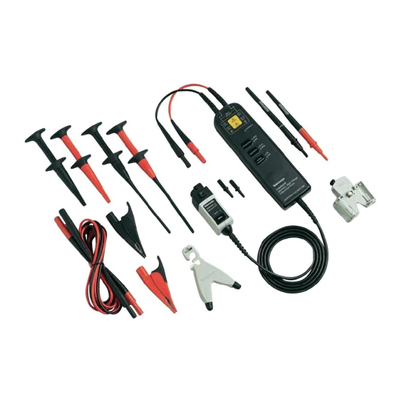
Page 19: Standard Accessories
If the wear indicator is visible, do not use the probe. Contact Tektronix Service for repair or replacement. Maximum ratings: 2300 V CAT I... - Page 20 Standard Accessories P5200A, P5202A & P5205A Probe standard accessories, (cont.) Item Description Hook clips (AC280-FL) Use these clips to make connections to component leads. Maximum ratings: 1000 V CAT III 600 V CAT IV Pincer clips (AC283-FL) These clips have a pair of finer contacts that close around leads on smaller components.
- Page 21 Standard Accessories WARNING. To avoid risk of electric shock or fire, do not use the P5210A test probe or hook tip accessories on CAT III or CAT IV circuits. Refer to the derating table below. To avoid risk of electric shock or fire, when using the P5210A test probe or hook tip accessories with the P5200A, P5202A and P5205A probes, do not use on circuits above 1000 V.
- Page 22 Standard Accessories P5210A Probe standard accessories Item Description Extender leads (196-3523-xx) The female banana connectors on one end of the leads fit into the probe input leads. Use the extender leads to connect the probe to the test probes below. The test probes accept the hook tips in the P5210A Probe accessory kit.
- Page 23 Standard Accessories P5210A Probe standard accessories, (cont.) Item Description Small hook tips (TASH) (020-3070-xx kit) Use these tips to access test points in tight spaces. Screw the hook tips onto the TATP test probes and then clamp the hooks onto the circuit. To reduce the risk of WARNING.
-
Page 24: Controls And Features
Controls and Features Controls and Features Controls and features Item Description Differential inputs The differential and common-mode input voltage ratings for the P5200A series probes differ between models. The highest ratings are for the P5210A probe and are rated for a maximum peak voltage of 5,600 V between the inputs. - Page 25 Controls and Features Controls and features, (cont.) Item Description Attenuation selector button and indicators Press the button to select between the voltage range (attenuation) settings of the probe. The range and units are indicated on the probe and may be displayed on the oscilloscope screen, depending on the oscilloscope model.
- Page 26 Controls and Features Controls and features Item Description Bandwidth limit button and indicators Press the button to limit the probe bandwidth to 5 MHz. The 5 MHz filter assists in the characterization and testing of power supplies in switch mode by removing all high frequency content, noise and harmonics from the measurement.
- Page 27 Controls and Features CD Contents The documentation CD included with this booklet contains pdf files of the P5200A Series High Voltage Differential Probes Instruction Manual, and other documents to help you understand how to take differential measurements with your probe.
Need help?
Do you have a question about the OI tek P5200A Series and is the answer not in the manual?
Questions and answers