Federal Signal Corporation Informer100 C Series Description, Specifications, And Installation Manual
Ip-enabled high-powered indoor/outdoor speaker
Hide thumbs
Also See for Informer100 C Series:
- Description, specifications, and installation manual (24 pages) ,
- Manual (60 pages)
Table of Contents
Advertisement
Quick Links
Advertisement
Table of Contents

Related Manuals for Federal Signal Corporation Informer100 C Series


Summary of Contents for Federal Signal Corporation Informer100 C Series
- Page 1 Informer100 Speaker Series C Models I-IP100AC and I-IP100DC IP-Enabled High-Powered Indoor/Outdoor Speaker Description, Specifications, and Installation Manual 25500641 Rev. A0 0820 Printed in U.S.A. © Copyright 2020 Federal Signal Corporation...
- Page 2 A copy of this limited warranty can also be obtained by written request to Federal Signal Corporation, 2645 Federal Signal Drive, University Park, IL 60484, email to info@fedsig.com or call +1 708-534-3400.
-
Page 3: Table Of Contents
Contents Safety Messages..............................5 Safety Messages to Installers ..........................5 General Description ..............................8 Introduction .................................8 Features ................................9 Ordering Information ............................10 Specifications ................................ 11 Installation ................................13 Determine a Suitable Location ..........................13 Wall Mounting ..............................14 Attaching the Mounting Brackets to the Speaker Housing ................14 Pole Mounting ..............................17 Large Pole Mounting (6-inch diameter or larger) ..................17 Small Pole Mounting (2-3/8 inch or 4-1/2 inch diameter poles) .............. - Page 4 Figures Figure 1 PS Series Push Button Stations (optional) ..................10 Figure 2 Informer100 Speaker with 225XL light ....................11 Figure 3 Bracket attached to speaker........................15 Figure 4 Width and height of bracket ........................15 Figure 5 Depth and height with bracket ......................16 Figure 6 Top view of speaker ..........................16 Figure 7 Ceiling mount ............................17 Figure 8 Bracket I-IP100-PMW ..........................17...
-
Page 5: Safety Messages
Safety Messages Safety Messages It is important to follow all instructions shipped with this product. This device is to be installed by trained personnel who are thoroughly familiar with the country’s electric codes and will follow these guidelines as well as local codes and ordinances, including any state or local noise-control ordinances. - Page 6 Safety Messages • Read and understand all instructions before installing, operating, or servicing this equipment. • This product shall be mounted at the minimum hearing distance of ten feet per FEMA guidelines limiting sound level exposure to 123 dBc maximum sound level. •...
- Page 7 Safety Messages • To reduce the risk of electric shock, do not perform any servicing other than what is contained in the operating instructions unless you are qualified to do so. Refer all servicing to qualified service personnel. Always test the Informer100 Speaker before using after repairs have been made.
-
Page 8: General Description
General Description General Description Introduction The Informer100 Speaker is an indoor and outdoor IP-enabled 100-watt speaker. Use the Informer100 as a warning and alert device with both audible and visual indicators. The audible capabilities include locally stored, high-quality, high-powered tones and voice. The visual indicators include the use of message board/scrolling display sign support and strobes, lights, and beacons. -
Page 9: Features
General Description Features The Informer100 has the following features; some features require the use of the Commander ® software system: • High-powered outdoor or indoor IP-enabled speaker for audible and visual alerts • Speaker rated at 120 dBa for tones and 114.5 dBa for voice at 10 feet •... -
Page 10: Ordering Information
General Description Ordering Information Table 1 Ordering Information Part Numbers Description I-IP100DC 24 Vdc 100 watt wall mount I-IP100AC 120/240 Vac 100 watt wall mount I-IP100-PM Small (6-inch or less) Pole Mount Bracket I-IP100-PMW Large (over 6-inch) Pole Mount Bracket I-IP100-OMNI Omni Directional Option for IP Speaker Informer100 Speaker requires Federal Signal Commander ®... -
Page 11: Specifications
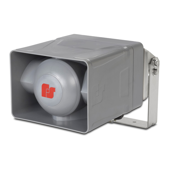
Specifications The following is a picture of the Informer100 Speaker shown with optional 225XL Warning Light. Figure 2 Informer100 Speaker with 225XL light Specifications Table 3 Electrical Operating Voltages I-IP100AC 120 Vac nom, 50/60 Hz or Switch-selectable 120 or 240 Vac 240 Vac nom, 50/60 Hz Operating Current I-IP100AC 120 Vac;... -
Page 12: Table 4 Visual Indications (Located On Internal Control Board.)
Specifications Audio Storage Warning siren audio, seven factory installed tones: Wail, Steady, Alternate Wail, Alternate Steady, Pulsed Wail, Pulsed Steady, Auxiliary Chime Prerecorded files—up to 4,000 voice or tone messages with 17 hours of total recording time Audio Data 8 bit 8 kHz mono wave (G7.11 μ-law) Audio Frequency response 300 Hz to 3000 Hz, +1 to -3 dB per octave Maximum Audio Output... -
Page 13: Installation
Installation JP5 Initiation inputs 1 and 2 – ISO Ground/Input 1 3 and 4 – ISO Ground/Input 2 5 and 6 – ISO Ground/Input 3 7 and 8 – ISO Ground/Input 4 NOTE: Each input is activated by shorting the two pins associated with the input. -
Page 14: Wall Mounting
Installation Wall Mounting The Informer100 Speaker comes standard with a bracket for vertical wall or pole mount with optional pole accessories. The standard mount can be flipped to allow ceiling mount. To wall mount the Informer100 Speaker: Find a suitable location to mount speaker. Use industry or company preferred practices when mounting hardware to structures. -
Page 15: Figure 3 Bracket Attached To Speaker
Installation Figure 3 Bracket attached to speaker 1/2" NPT Sealed from the factory 1/4-20 x 5/8" screws (6) Note the orientation of this curved slot with respect to the “FS” on the side of the housing. 3/8-16 x 1" bolts (4) Figure 4 Width and height of bracket 2.00"... -
Page 16: Figure 5 Depth And Height With Bracket
Installation Figure 5 Depth and height with bracket 6.68" (16.97 cm) 2.53" (6.43 cm) 10.09" 2.00" (25.63 cm) (5.08 cm) 12.87" (32.69 cm) Figure 6 Top view of speaker 1/2" NPT Sealed from the factory 12.87" (32.69 cm) 10.09" (25.63 cm) 8.90"... -
Page 17: Pole Mounting
Installation Figure 7 Ceiling mount Pole Mounting The Informer100 comes standard with a bracket for vertical wall or pole mount with optional pole accessories. Large Pole Mounting (6-inch diameter or larger) Use the following procedure if mounting the speaker with the optional I-IP100-PMW bracket: Find a suitable location to mount speaker. -
Page 18: Small Pole Mounting (2-3/8 Inch Or 4-1/2 Inch Diameter Poles)
Installation Small Pole Mounting (2-3/8 inch or 4-1/2 inch diameter poles) Use the following procedure if mounting the speaker with the optional I-IP100-PM bracket: Find a suitable location to mount speaker. Use industry or company preferred practices when attaching hardware to poles or other structures. Remove the speaker U-shaped bracket, store the pivot/lock bolts. -
Page 19: Mounting With Omni Direction Bracket (2-3/8 Inch Diameter Pole)
Installation Mounting with Omni Direction Bracket (2-3/8 inch diameter pole) Use the I-IP100-OMNI bracket to create an omni-directional speaker. The speaker is mounted as described in the Small Pole Mount section with the omni bracket mounted at a distance of 2.0 inches from the speaker. Use the following procedure if mounting the speaker with the optional I-IP100-OMNI bracket: Identify the desired location for the bracket. -
Page 20: Mounting Without Bracket
Installation Mounting without Bracket You can mount the speaker directly to the mounting surface without the bracket. Use installer-supplied 1/4-20 fasteners that are suitable for the mounting surface. See Figure 11 for the hole center dimensions. Figure 11 Surface mount hole center dimensions 7.39"... -
Page 21: Opening The Housing
Installation Opening the Housing Tools required: • 3/8-inch socket • 6-inch extension To open the housing, loosen the four cover screws while supporting the housing, so it does not fall. (The cover screws are retained in the housing.) The front of the unit is heavy, but it is attached to the rear housing with a pivot hinge to allow ease of service. -
Page 22: Figure 13 Dc Controller Board
Installation I-IP100DC 24Vdc Model • JP4 is used for relay 1 (pins 1 and 2) and provides an interface for DC powered strobes using (pins 3 and 4). • JP6 and JP7 can be used for access to 24 Vdc to power strobes or other external equipment. -
Page 23: Figure 14 Ac Controller Board
Installation I-IP100AC 120/240 Vac Model • JP4 is used for relay 1 (pins 1 and 2) and provides an interface for AC powered strobes using (pins 5 and 6). • JP6 and JP7 can be used for access to 120 or 240 Vac to power strobes or other external equipment. -
Page 24: Wiring To The Relay/Electronic Outputs
Installation Wiring to the Relay/Electronic Outputs JP4 – Relay Outputs 1 and 2 mechanical relay Normally Open. 3 – DC solid-state relay, (+) DC power. 4 – DC solid-state relay, Switched (+) DC power to strobe or light. 5 – AC solid-state relay power 6 –... -
Page 25: Figure 15 Fb2Pst Strobe With Informer100 Speaker
Installation See the following list of Federal Signal AC powered warning lights that may be controlled by the IP100: • 121S Vitalite ® Rotating Warning Light • 225 Electraray ® Rotating Warning Light • 225X Electraray ® Hazardous Location Rotating Warning Light •... -
Page 26: Figure 16 151Xst Strobe With Informer100 Speaker
Installation Figure 16 151XST Strobe with Informer100 Speaker 3/4" NPT Pipe Nipple 3/4" NPT to 1/2" NPT Reducer, 1/2" NPT Pipe Nipple, 3" overall length (Recommended, customer supplied) Side View Front View For a 151XST Strobe, the following is recommended (customer supplied): 151XST Strobe Installed on Informer100 •... -
Page 27: Ethernet Port
Installation For a 225XST/225XL Strobe, the following is recommended (customer supplied): 1/2-inch NPT Pipe Nipple (3 inches overall length). Ethernet Port The Informer100 Speaker has an 8-pin Ethernet port for connecting to the network. Ethernet wire runs must be less than 328 feet from the nearest network switch. Do not install in a conduit carrying high voltage. -
Page 28: Closing The Housing
Getting Service Closing the Housing To close the housing: Verify that the cover gasket is in the groove around the perimeter of the rear cover. If the front of the unit was removed, lift the front of the Informer100 to allow the hinge pin to be installed, align the front unit with the rear cover and attach the hinge pin with retaining clip.
Need help?
Do you have a question about the Informer100 C Series and is the answer not in the manual?
Questions and answers